
Electrolytic Capacitors: Aluminum vs. Tantalum Guide
Electrolytic capacitors, with their high-capacity and low-cost features, have become core components in power supply filtering and low-frequency circuits.
Get Your PCB Quote!
Table of Contents
- 1. Co je elektrolytický kondenzátor?
- 2. Jaké jsou pracovní principy elektrolytických kondenzátorů?
- 3. Jaké jsou klíčové vlastnosti elektrolytických kondenzátorů?
- 4. Jaké jsou hlavní typy elektrolytických kondenzátorů?
- 5. Jaké jsou rozdíly mezi elektrolytickými kondenzátory a konvenčními kondenzátory?
- 6. Kde se používají elektrolytické kondenzátory?
- 7. Jak identifikovat elektrolytické kondenzátory?
- 8. Jaké jsou vývojové trendy elektrolytických kondenzátorů?
- 9. obyčejný Brandy za Elektrolytické kondenzátory
- 10. Často kladené otázky k elektrolytickým kondenzátorům
- 11. Shrnutí
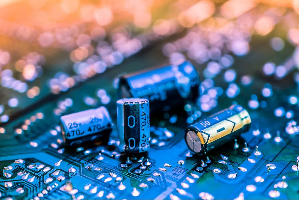
An electrolytic capacitor is a polar capacitor with an electrolyte as the cathode. It achieves high-capacity energy storage through the oxide film (such as Al₂O₃ or Ta₂O₅) formed on the surface of the anode metal. Its core structure consists of an anode metal foil (aluminum or tantalum), an oxide film dielectric, and a cathode material impregnated with electrolyte. The name derives from the crucial role played by the electrolyte in the cathode.
1. What is an Electrolytic Capacitor?
An electrolytic capacitor is a type of capacitor that has high capacitance and positive and negative electrodes. Unlike other types of capacitors, an electrolytic capacitor uses an electrolyte as the cathode or anode material. Through chemical reactions, an extremely thin oxide film forms on the surface of the metal foil as the dielectric. Despite its thinness, this oxide film can withstand high voltages, thereby achieving high capacitance. Electrolytic capacitors are often used in circuits because of their unique structure. They are particularly good for low-frequency and high-capacity applications.
2. What are the Working Principles of Electrolytic Capacitors?
1) Basic Structure
Positive Electrode: A metal foil (like aluminum or tantalum) is covered with an insulating oxide layer (such as aluminum oxide or tantalum pentoxide). This layer serves as a dielectric.
Negative Electrode: The cathode is made of a conductive material and an electrolyte (liquid or solid). The electrolyte is the most important part of the cathode.
Separator: Insulating paper impregnated with electrolyte separates the positive and negative electrodes, preventing short circuits.
2) Working Principle
Charging Process: A applied voltage attracts electrons from the positive metal foil to the negative electrode. The positive ions in the electrolyte move toward the negative electrode. There, they join with the positive electrode. Together, they create an electric field that stores charge.
Discharging Process: When it is connected to an electrical circuit, the stored charge is released through the electrolyte. This releases it to perform filtering or power supply functions.
Polarity Limitation: Reverse voltage can cause the oxide film to break down, causing damage or even an explosion of the capacitor.
3. What are the Key Features of Electrolytic Capacitors?
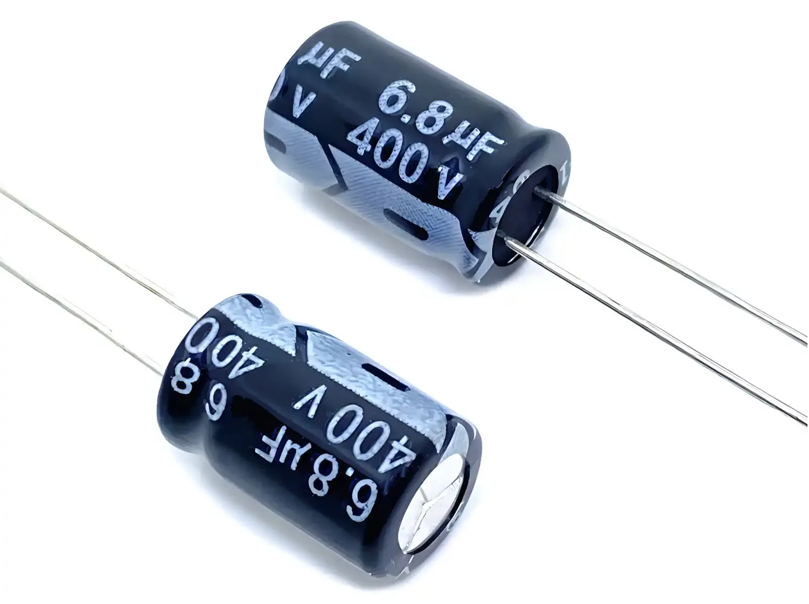
Polarity Sensitive: Strictly distinguish between positive and negative terminals. A reverse connection can cause electrolyte breakdown, leading to bulging, leakage, or even explosion. Polarity is typically indicated by a colored band (negative), lead length, or a “+” symbol on the outer casing.
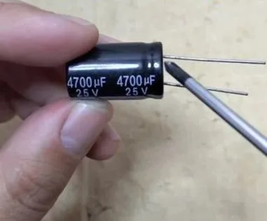
High Capacitance: Electrolytic capacitors use an oxide film to increase the surface area of the electrodes. This allows them to have capacities ranging from hundreds to tens of thousands of microfarads (μF). Aluminum electrolytic capacitors usually have a capacitance range of 1 μF to 47 mF, and a unit volume density of 1 μF to 1,000,000 μF. This is much more than that of ordinary ceramic or film capacitors. They are great for applications that need a lot of energy storage, like power supply filtering.
High Operating Voltage: Oxide films can withstand high voltages and are commonly used in power electronic equipment (such as motor drives). However, be aware that reverse voltages exceeding 1V may cause failure.
Cost and Lifespan: Aluminum electrolytic capacitors offer low cost and simple manufacturing, but their lifespan is limited by electrolyte aging. Tantalum/niobium capacitors offer greater stability but are more expensive.
Limitations: There are problems such as large leakage current, poor frequency characteristics, and limited lifespan. However, solid electrolytic capacitors optimize ESR and lifespan through conductive polymer materials.
4. What are the Main Types of Electrolytic Capacitors?
Electrolytic capacitors can be classified based on three dimensions: material, electrolyte state, and structure. The details are as follows:
4.1 Classification by Anode Material (Valve Metal)
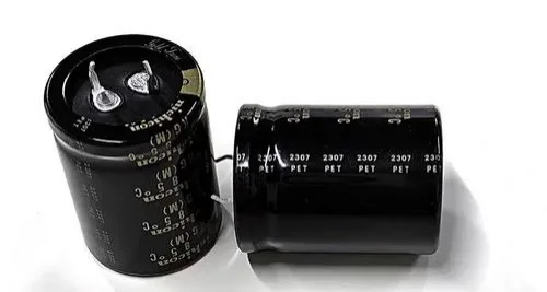
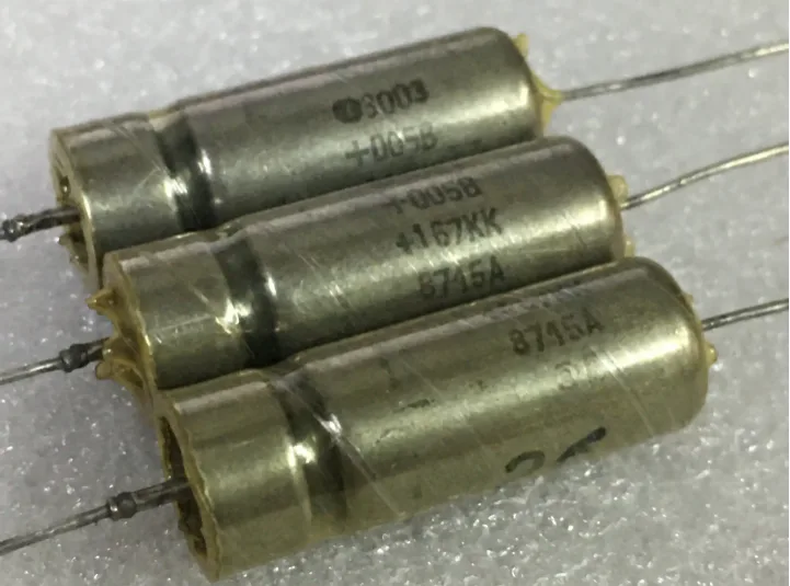
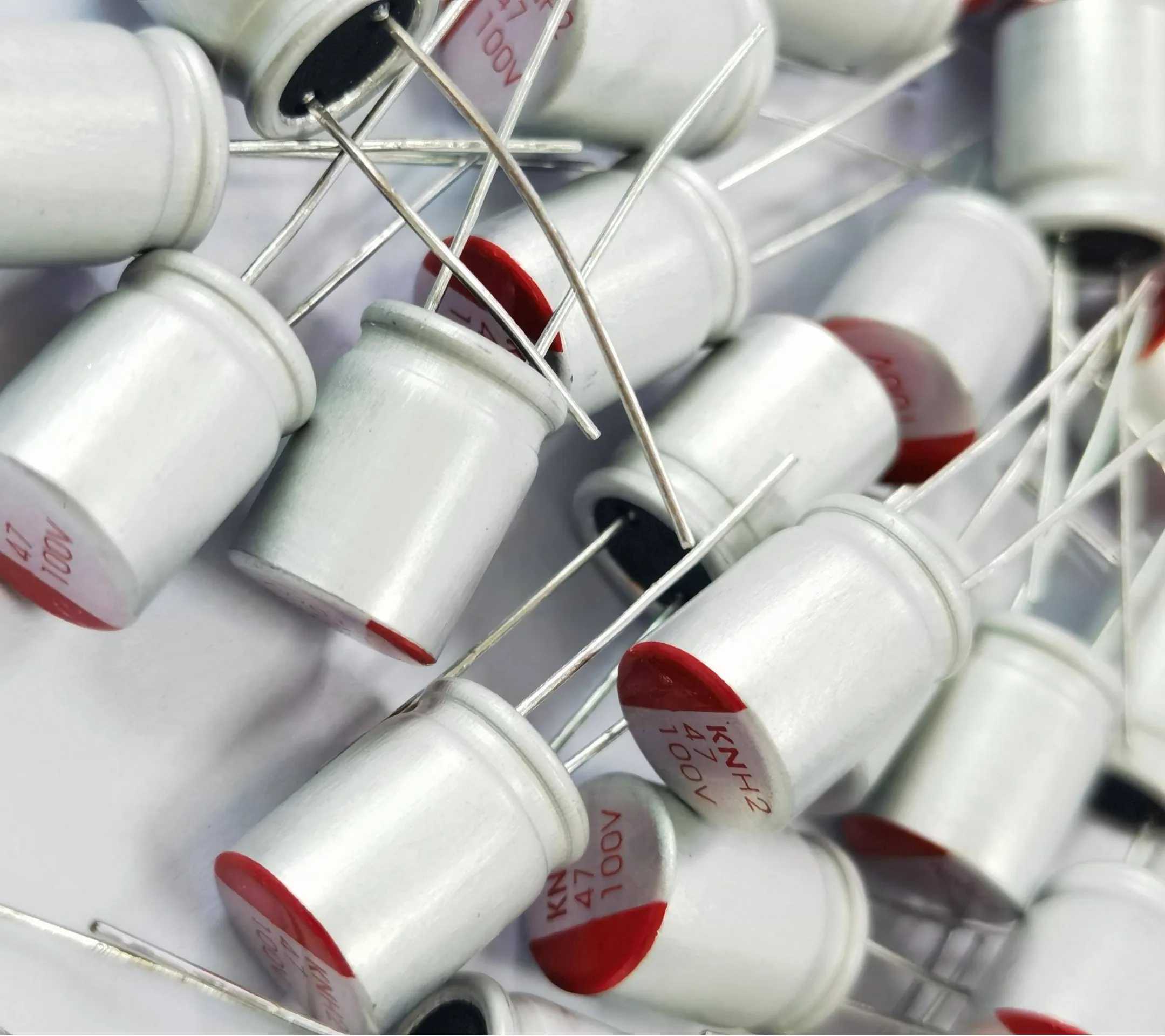
1) Aluminum Electrolytic Capacitors
Features: Large capacity and low price, but high ESR and poor stability. Suitable for power supply filtering, low-frequency bypass, and other applications.
Subdivided: Based on the electrolyte state, they can be divided into liquid aluminum capacitors (traditional electrolyte type) and solid aluminum capacitors.
2) Tantalum Electrolytic Capacitors
Features: Low ESR, high stability, high temperature resistance, and suitable for high-frequency circuits (such as RF and pulse circuits), but they are relatively expensive.
Cathode Material: Typically uses MnO2 solid electrolyte, which has better conductivity than liquid electrolytes.
3) Niobium Electrolytic Capacitors
Features: It combines the high capacity of aluminum capacitors with the low ESR of tantalum capacitors, but is less commonly used and costs more.
4.2 Classification by Electrolyte State
Liquid Electrolytic Capacitors
Use an electrolyte as the cathode. They have strong voltage resistance, but are volatile at high temperatures and have a shorter lifespan.
Solid electrolytic capacitors
Solid electrolytic capacitors, such as MnO2 or polymer electrolytes, offer low ESR and high-temperature resistance, but are relatively expensive.
4.3 Classification by Structure
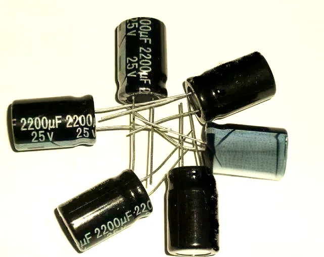
Foil Wound Type
Common in aluminum electrolytic capacitors, formed by winding aluminum foil.
Sintered Type
Mostly used in tantalum capacitors, the anode is sintered.
4.4 Classification by Other Characteristics
Non-polarity Type: A back-to-back design achieves bidirectional withstand voltage.
High-Frequency/Low-ESR Type: It is designed to work well at high frequencies, like in small electrolytic capacitors (1μF to 100μF) that are used to filter noise.
5. What are the Differences between Electrolytic Capacitors and Conventional Capacitors?
Electrolytic capacitors and conventional capacitors differ significantly in structure, performance, and application scenarios. The following are the main differences:
1) Structure and Material Differences
Electrolytic Capacitors: Use a metal oxide, like aluminum oxide, as the dielectric layer. This makes an extremely thin insulating layer through an electrochemical process. The cathode is formed by an electrolyte or a solid electrolyte. The structure is generally a wound or stacked structure.
Conventional Capacitors: Use non-polar materials such as ceramic and polypropylene as the dielectric layer. The structure is a parallel plate or multilayer design, and there is no electrochemical reaction.
2) Performance Parameter Comparison
Capacity and Volume: Electrolytic capacitors have high capacity per unit volume (μF level), suitable for large-capacity needs; conventional capacitors have smaller capacity (pF to nF level).
Polarity: Electrolytic capacitors have positive and negative poles, and they can be damaged if they are connected incorrectly. Conventional capacitors (such as ceramic and film capacitors) are non-polar.
Frequency Characteristics: Electrolytic capacitors have a high ESR (0.1-1Ω) and poor high-frequency performance; ordinary capacitors have an ESR as low as mΩ and are suitable for high-frequency circuits.
Lifespan: Electrolytic capacitors don’t last very long (2,000 to 10,000 hours) because of electrolyte volatilization. Ordinary capacitors last much longer (over 100,000 hours).
3) Application Scenarios
Electrolytic Capacitors: Low-frequency, high-capacity applications such as power supply filtering and energy storage.
Ordinary Capacitors: High-frequency decoupling, resonant circuits (such as ceramic capacitors used in CPU power supplies).
4) Other Differences
Voltage Resistance: Electrolytic capacitors typically have a voltage resistance below 500V, while ordinary capacitors can reach several thousand volts.
Temperature Characteristics: The capacitance of electrolytic capacitors varies significantly with temperature (±20%), while ordinary capacitors are more stable.
6. Where are Electrolytic Capacitors Used?
Electrolytic capacitors are important components of electronic circuits. They are used in many industries, including consumer electronics, industrial control, new energy, and automotive electronics.
1) Consumer Electronics
Typical Applications: They are primarily used for power filtering, signal coupling, and energy storage in products such as televisions, audio systems, monitors, computers, and air conditioners.
Specific Applications: Aluminum electrolytic capacitors are used in many devices, like monitors, CD players, power supplies, and motherboards. They make up 45% of the market.
2) Industrial and Communications
Industrial Control: They are used in inverters, CNC systems, servo systems, and wind turbines, accounting for 23%.
Communications: They are used for voltage stabilization in power modules, accounting for 7%.
3) New Energy and Automotive Electronics
New Energy Vehicles: They are used in battery management systems and motor drive circuits for energy storage and filtering.
Photovoltaic and Energy Storage: They play a key role in inverters and energy conversion systems.
4) Other Specialty Applications
Military and Aerospace: High-reliability aluminum electrolytic capacitors are used in equipment operating in extreme environments.
High-speed Railway: Traction converters and signaling systems must withstand high vibrations.
Electrolytic capacitors have many uses because they can store a lot of energy, they are cheap, and they can be used in different types of circuits. Technology is making them more common in new energy and automotive electronics.
7. How to Identify Electrolytic Capacitors?
To identify the quality of electrolytic capacitors, it is important to do a visual inspection, run some tests, and check their performance. The following are specific methods:
7.1 Visual Inspection
Physical Deformation: Observe for bulging on the top of the capacitor, swelling on the bottom, or cracking of the casing. A bulging explosion-proof valve on an aluminum electrolytic capacitor indicates failure. SMD capacitors also need to be replaced if they develop microcracks or if the terminal electrodes come loose.
Evidence of Leakage: Inspect the leads and circuit board for brown or white crystals. Leakage can corrode the PCB and cause circuit instability.
Discoloration Due to High Temperature: A burnt or blackened casing indicates long-term overload. An infrared thermometer should be used for testing. A temperature exceeding the specified value by 20% indicates a potential risk.
7.2 Multimeter Testing
1) Resistance Measurement
Normal Capacitance: When the test leads touch, the resistance drops rapidly and then returns to “0” (low).
Short/Open: The resistance remains at 0Ω or “0” (low).
Abnormal Leakage: The resistance remains stagnant and does not recover.
2) Capacitance Measurement
If the measured value deviates from the nominal value by more than ±20%, the capacitor must be replaced.
3) ESR Testing
The normal ESR range for aluminum electrolytic capacitors is 0.1-10Ω, while for tantalum capacitors, it should be less than 0.5Ω.
7.3 Testing with Professional Instruments
LCR Bridge: Accurately measure capacitance (accuracy 0.1%) and dissipation factor (D value > 0.15 requires replacement).
Oscilloscope Observation: If the ripple voltage of a power supply filter capacitor exceeds 10% of the nominal value, it is considered abnormal.
Leakage Current Test: Apply the rated voltage for 1 minute; the leakage current should be <5μA/μF (e.g., <500μA for a 100μF capacitor).
7.4 Key Points for Testing Different Types of Capacitors
Electrolytic Capacitors: Focus on ESR and capacitance degradation. Operating voltage exceeding 80% of the rated value will shorten the capacitor’s lifespan.
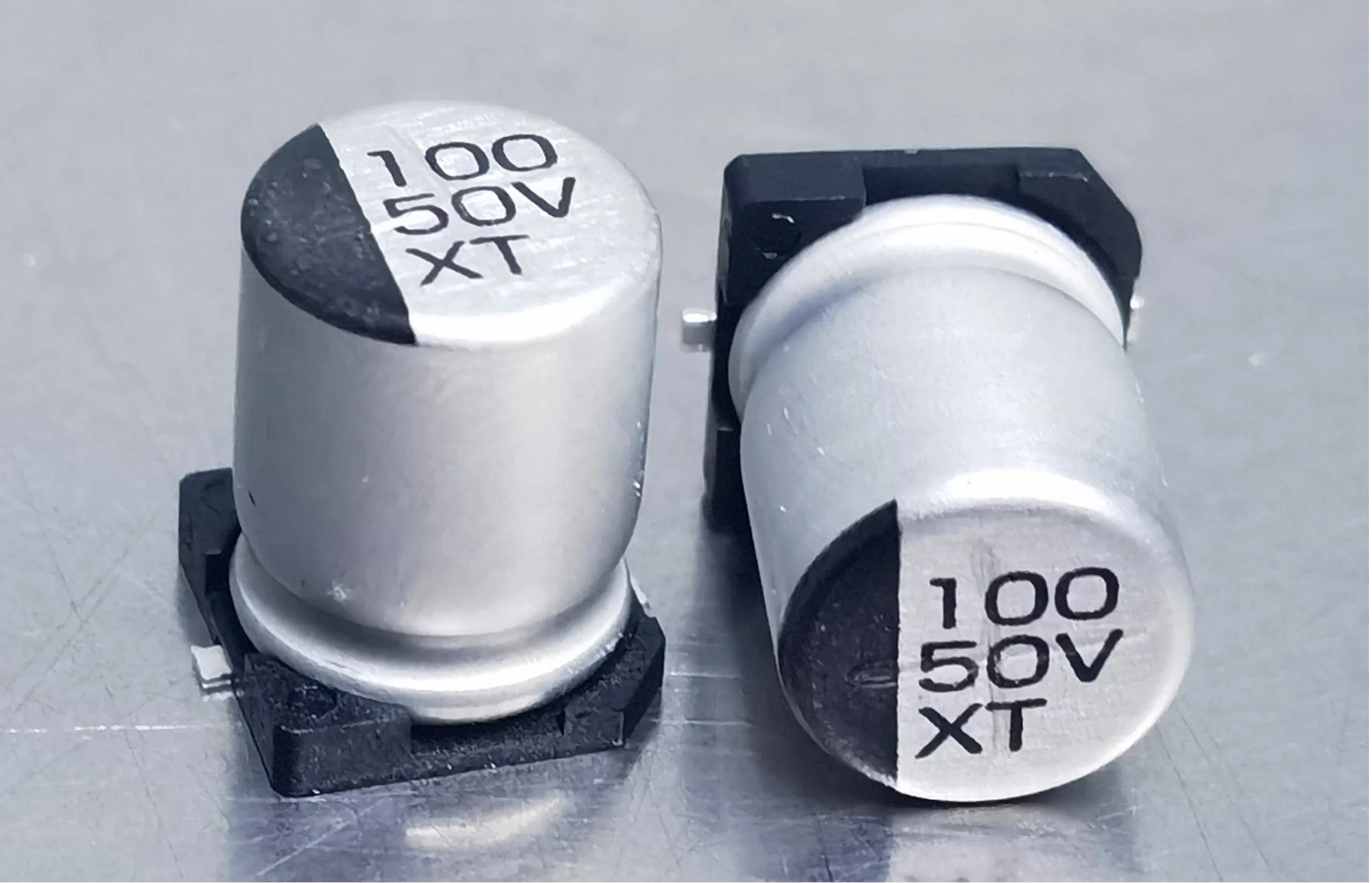
SMD Electrolytic Capacitors: Pay attention to the clarity of the labeling; incorrect polarity may cause breakdown.
7.5 Safety and Maintenance Recommendations for Electrolytic Capacitors
High-voltage Capacitors: Fully discharge before testing. Tantalum capacitors must not exceed 50% of their rated voltage.
Storage Requirements: Electrolytic capacitors must be regularly activated (every two years) and protected from humid environments.
The above methods can be used to systematically evaluate the quality of electrolytic capacitors. Focus on long-life capacitors (ones that can withstand 105°C/5000 hours) and follow derating principles (which means selecting twice the operating voltage for withstand voltage). This will make them more reliable.
8. What are the Development Trends of Electrolytic Capacitors?
1) Solid-State Transformation
Solid-state aluminum electrolytic capacitors, which use conductive polymer materials, significantly outperform traditional liquid-based products in three key areas: high-temperature resistance (-55°C to 150°C), long life (over 100,000 hours), and safety (no risk of explosion). They have 15% less ESR and are three times more energy-dense. This makes them a popular replacement for liquid-based capacitors in new energy vehicles and 5G base stations.
2) Material and Process Breakthroughs
Nanoscale oxide composite electrolytes and multilayer winding technology are driving performance improvements.
They comply with environmental regulations (such as RoHS 3.0) by using lead-free processes and electrolyte recycling technologies.
Laser welding technology replaces riveting, improving product consistency.
9. Common Brands for Electrolytic Capacitors
TDK
Würth Elektronik
Rubycon
Nichicon
KEMET
KYOCERA
Panasonic
SparkFun
TE
Vishay
Yageo
…
10. Electrolytic Capacitors FAQs
1) What is the electrolytic capacitor?
An electrolytic capacitor is a special kind of capacitor. It has a metal that has been treated to form an insulating oxide layer. This metal is called the anode or positive plate. This oxide layer acts as the capacitor’s dielectric.
2) Why use electrolytic capacitors?
Electrolytic capacitors help filter out noise and maintain voltage levels near integrated circuits. In short, electrolytic capacitors are good for providing large capacitance values over a wide range, usually in a stable environment.
3) What is the difference between an electrolytic capacitor and a normal capacitor?
Capacitors typically consist of two conductive plates (electrodes) separated by an insulator (dielectric). Electrolytic capacitors are polarized. This means they only work when the voltage at one terminal is consistently higher than the other.
4) Can an electrolytic capacitor be used for AC or DC?
It can only be used with a DC power supply. Applying a DC voltage externally forms an oxide layer on the anode surface. Electrolytic capacitors have polarity. If you connect the terminals in reverse polarity, you will damage the capacitor. Therefore, they cannot withstand pure AC power.
5) Why do we use an electrolytic capacitor in a power supply?
Electrolytic capacitors are an essential component of AC-DC power supplies. They provide high Capacitance x Voltage (CV) and low Equivalent Series Resistance (ESR) in low-volume packages. There’s no alternative part that can do the job cost-effectively.
6) Why do electrolytic capacitors fail?
Electrolytic capacitors can fail due to short circuits, circuit damage, or even explosion. Most electrolytic capacitors have a problem that causes their performance to get worse over time. This problem is usually caused by the electrolyte either evaporating or leaking.
7) Is an electrolytic capacitor a battery?
No. There are many ways to store energy, and batteries and capacitors are commonly used in circuits and electronic devices. Batteries store energy in chemicals, while capacitors store energy in electric fields.
8) What are the disadvantages of electrolytic capacitors?
Limited Temperature Range: Electrolytic capacitors can only handle certain temperatures. They cannot be used in extreme temperatures.
High ESR: Electrolytic capacitors have a high ESR, which can limit their performance in certain applications.
9) How to tell if a capacitor is electrolytic?
Generally speaking, there are two types of polarized capacitors: electrolytic and tantalum. Both types will have some kind of polarity indicator. They also typically come in larger values (μF and above). Any capacitor less than 1μF is most likely a ceramic capacitor.
11. Summary
Electrolytic capacitors, with their high-capacity and low-cost features, have become core components in power supply filtering and low-frequency circuits. However, their polarity restrictions and temperature sensitivity require careful consideration. When selecting an electrolytic capacitor, consider its capacitance, withstand voltage, ESR, operating temperature range, and lifespan.
Aluminum electrolytic capacitors are economical and practical, while tantalum electrolytic capacitors offer excellent performance. Proper identification of polarity markings can help avoid explosion risks. If you need to use this for high-frequency applications, you should think about using low-ESR ceramic capacitors together with electrolytic capacitors to deal with the problems that electrolytic capacitors have. Also, make sure you don’t have too much or too little voltage, or that the polarity is reversed. This will make the components last longer and keep the circuit safe.
Table of Contents
- 1. Co je elektrolytický kondenzátor?
- 2. Jaké jsou pracovní principy elektrolytických kondenzátorů?
- 3. Jaké jsou klíčové vlastnosti elektrolytických kondenzátorů?
- 4. Jaké jsou hlavní typy elektrolytických kondenzátorů?
- 5. Jaké jsou rozdíly mezi elektrolytickými kondenzátory a konvenčními kondenzátory?
- 6. Kde se používají elektrolytické kondenzátory?
- 7. Jak identifikovat elektrolytické kondenzátory?
- 8. Jaké jsou vývojové trendy elektrolytických kondenzátorů?
- 9. obyčejný Brandy za Elektrolytické kondenzátory
- 10. Často kladené otázky k elektrolytickým kondenzátorům
- 11. Shrnutí

Get Your PCB Quote!


