PCB Material Selection: FR-4, Rogers, PTFE & Aluminum
The choice of PCB material will affect the electrical performance, thermal performance, mechanical performance and reliability of the final electronic products.
Get Your PCB Quote!
Table of Contents
If you have ever experienced PCB warping during reflow, failed EMI testing or unusual signal strength degradation in high-speed circuits, the choice of PCB material is probably to blame. Selecting the right PCB material is a frequently overlooked aspect of design decisions, yet it often becomes the root cause of issues that arise later, even after PCB production. For PCB buyers or designers, understanding PCB material is crucial. The choice of PCB substrate material impacts the electrical performance, thermal performance, mechanical properties, and reliability of the final electronic products.
1. Why is Choosing the Right PCB Material Important?
Selecting the right PCB material is critical to the performance and reliability of electronic devices. PCB material is like the foundation of a house. It supports all components, including board layers, copper traces and components, and determines how the PCB will perform when subjected to stress, heat, frequency or environmental exposure.

1) Ensuring Electrical Performance
High-frequency applications (e.g., 5G, IoT devices) require materials with low dielectric constant (Dk) and dissipation factor (Df) (e.g., PTFE or modified FR-4) to minimize signal attenuation and distortion. For instance, communication equipment (1–10 GHz) demands substrates with εr = 3.8–4.2 to prevent impedance mismatch.
2) Enhancing Thermal Management Capabilities
High-power devices require highly thermally conductive materials (e.g., aluminum or ceramic substrates) for heat dissipation to prevent component overheating failures. Industrial-grade PCBs need Tg ≥ 150°C, while automotive electronics require Tg ≥ 170°C to withstand extreme temperatures. FR-4 has a thermal conductivity of only 0.3 W/m·K, whereas ceramics can reach 30 W/m·K.
3) Maintaining Mechanical Reliability
Materials must withstand thermal cycling, humidity, and mechanical stress. For instance, outdoor IoT devices require moisture-resistant coatings, while automotive electronics demand Z-axis CTE < 70 ppm/°C to prevent solder joint cracking.
4) Balancing Cost and DFM(Design for Manufacturability)
FR-4 remains the universal choice thanks to its cost-effectiveness. However, high-end applications (e.g. in the aerospace industry) may require premium materials such as silicon carbide. Standard materials reduce manufacturing costs during mass production.
5) Considering Environmental Sustainability and Compliance
Halogen-free, recyclable materials comply with regulations like RoHS, impacting market access. For instance, industrial control PCBs recommend halogen-free FR-4 substrates.
6) Optimizing Signal Integrity
High-speed signals (e.g., above 15Gbps) require stripline layers and low-loss substrates (e.g., MEGTRON6) to minimize insertion loss and crosstalk.
PCB material selection must holistically consider the electronic product’s application environment, performance requirements, and cost, as these factors directly impact the product’s lifespan and market competitiveness.
2. What are the Common Types of PCB Material?
2.1 Organic Substrates
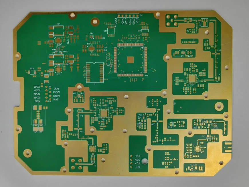
1) FR-4 (Fiber-Reinforced Epoxy)
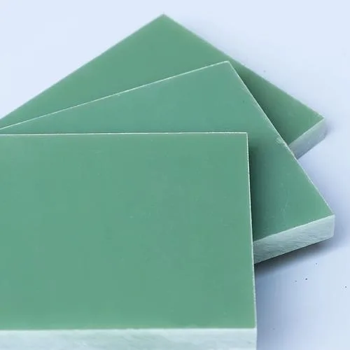
This is the most commonly used rigid board material. It offers excellent mechanical strength, electrical insulation and heat resistance. It offers good value for money and is widely used in communication equipment, computers, and consumer electronics. Its dielectric constant ranges from approximately 4.5 to 5.5, making it suitable for general circuit design.
2) High-Tg FR4
Similar to FR4, but with enhanced thermal resistance. This represents a prudent upgrade for lead-free PCB assembly or applications demanding superior thermal performance, such as power supplies or automotive controllers. High-Tg PCBs feature a glass transition temperature (Tg) of 170°C or higher, compared to the 130°C to 150°C Tg of standard FR4 PCBs.
3) Polyimide (PI)
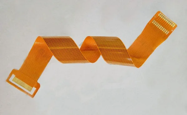
This material is renowned for its exceptional flexibility and lightweight properties. It offers high-temperature resistance and chemical corrosion resistance, making it suitable for flexible printed circuits (FPC), rigid-flex boards, and high-frequency applications such as aerospace and medical devices (particularly wearable applications).
4) Phenolic Paper Substrates (e.g., FR-1/FR-2)
Low-cost but with inferior performance, primarily used in low-end electronics.
2.2 Metal Substrates
1) Aluminum Substrate
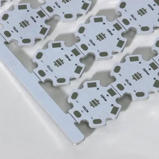
Offers superior thermal performance compared to FR4 at a lower cost, commonly used in LED lighting and automotive electronics. Its structure comprises a circuit layer, insulating layer, and aluminum base layer.
2) Copper Substrate
It exhibits better thermal conductivity than aluminium substrates and possesses excellent mechanical strength, enabling robust and durable PCB designs. It is suitable for high-frequency circuits and high-power equipment, such as high-current circuits, power supplies and motor controllers, but it is more expensive.
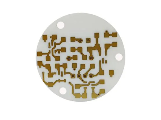
2.3 Ceramic Substrates
Alumina/Silicon Nitride Substrates
Ceramics offer optimal thermal conductivity and can withstand high voltages and power levels. They exhibit excellent high-temperature and high-frequency performance, making them commonly used in high-power applications such as microwave communications and radar systems.
2.4 Special Materials
1) Polytetrafluoroethylene (PTFE)
This material is soft, flexible, and has a low dielectric constant (approximately 2.1), making it suitable for high-speed signal transmission. However, it is challenging to process. PCB buyers must consult their PCB manufacturer regarding inventory availability before making decisions (procurement may take up to three months) and confirm storage duration (recommended within 45 days).
2) Silicon Carbide (SiC)
High-temperature resistant with excellent thermal conductivity, but costly. Primarily used in automotive electronics and aerospace applications.
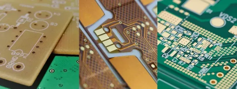
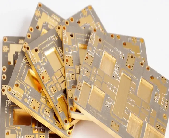
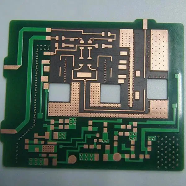
3) Rogers (RO4350B, RO4003C, etc.)
Used for RF and high-speed/high-frequency PCBs demanding stringent signal integrity. Rogers materials feature low dielectric constants (approx. 3.48) and stable thermal properties, making them ideal for high-frequency circuits. Many Rogers high-frequency materials are PTFE-based composites, such as the common Rogers RO4000, RO3000, RT/duroid series, etc.
3. What Factors Affect the Performance of PCB Material?
The performance of PCB materials is influenced by multiple factors and can be broadly categorized into four main types: electrical performance, structural characteristics, thermal performance, and mechanical performance. The details are as follows:
3.1 Electrical Performance
Dielectric Constant (Dk)
The dielectric constant directly affects the speed and loss of signal transmission; the lower the value, the faster the transmission. For instance, the dielectric constant of the widely used material FR4 is 4.7, resulting in a signal propagation velocity of around 138 m/μs. In contrast, polytetrafluoroethylene achieves a velocity of 202.26 m/μs with an εr of 2.2. Materials with stable dielectric constants and low frequency dependence are essential for high-frequency applications.
Dissipation Factor (Df)
The tangent of loss angle reflects signal energy dissipation. A lower value indicates less attenuation of high-frequency signals. FR4 has tanδ≈0.02, causing over 5dB of attenuation per meter for 10GHz signals, whereas PTFE material (tanδ≤0.0015) exhibits only 0.5dB of attenuation.
3.2 Structural Characteristics
Glass Weave Pattern
Weave gaps in glass fiber cloth cause dielectric constant variations, leading to signal dispersion and loss—particularly pronounced in high-frequency circuits.
Copper Conductor Roughness
Increased surface roughness of copper foil intensifies the skin effect, resulting in high-frequency signal distortion and impedance fluctuations.
3.3 Thermal Performance
Thermal Conductivity
Highly thermally conductive materials, such as ceramic substrates, are suitable for high-power applications. In contrast, FR4 has low thermal conductivity and requires an external heat dissipation design.
Glass Transition Temperature (Tg)
Tg denotes the transition temperature at which the substrate resin undergoes a mechanical state change due to rising ambient temperature, shifting from a glassy state to a highly elastic (rubber-like) state when heated. Tg determines the material’s maximum temperature tolerance. FR4 typically has a Tg of 130°C and may soften or deform in high-temperature environments. Compared to conventional PCBs, high-performance boards with multiple layers, greater thickness and larger dimensions should exhibit superior thermal resistance or higher Tg temperatures.
3.4 Mechanical Performance
Bending Strength
FR4 has a high bending strength thanks to its glass fibre reinforcement, but it is relatively brittle. Flexible substrates, such as polyimide, are better suited to bendable applications.
Coefficient of Thermal Expansion (CTE)
CTE refers to the linear dimensional change of substrate material per unit temperature increase when heated. Mismatched CTE can cause copper foil delamination, requiring particular attention to thermal expansion consistency across layers in multilayer boards.
3.5 Other Factors
Flame Retardancy
FR4 is a flame-retardant material (UL94-VO), but non-flame-retardant materials (UL94-HB) offer lower costs.
Environmental Adaptability
Tests such as humidity, heat, and salt spray can validate the material’s long-term reliability.
4. How to Select the Right PCB Material?
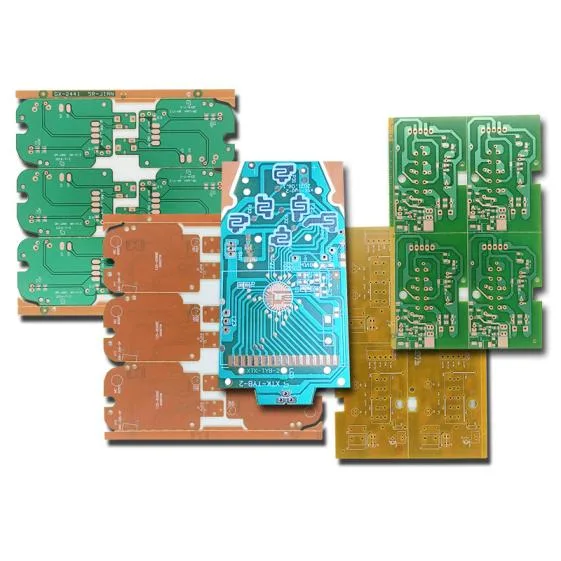
From FR4 and polyimide to PTFE and aluminium-backed printed circuit boards, each PCB material has its own advantages and disadvantages. Some are ideal for everyday electronics, while others are designed for greater flexibility, faster signal transmission or better thermal performance. To make the most informed choice that aligns with your product’s performance requirements, it is essential to understand the characteristics of each material.
4.1 Matching Materials to Applications
For basic consumer goods, FR-4 is typically a solid choice—it’s affordable and reliable. If your project involves medical devices such as wearables or high-tech tools, you will require materials that can withstand heat while maintaining stable performance, such as polyimide or PTFE. For industrial equipment, prioritize heat-resistant and shock-resistant materials like aluminum-backed printed circuit boards.
4.2 Balancing Performance, Environment, and Cost
Ask yourself: Will the circuit board get hot, move, or get wet? If so, choose robust, heat-resistant materials. If high-speed signals are required, seek materials with low signal loss. Naturally, ensure the material fits your budget without compromising performance.
4.3 Adhering to Safety and Compliance Regulations
Certain projects require compliance with safety standards, such as the Restriction of Hazardous Substances Directive, or the incorporation of fire-retardant properties, particularly in applications relating to the medical sector, the automotive industry, or consumer electronics.
4.4 Application-Based PCB Material Recommendation Table
| Application | Recommended PCB Material |
| Basic Consumer Devices | FR4 |
| Automotive Electronics | High-Tg FR4 or Polyimide(PI) |
| RF/5G/High-Frequency | Rogers, PTFE |
| Aerospace/Satellite | Polyimide, PTFE(PI), Ceramic |
| Industrial Controls | High-Tg FR4 or Ceramic |
| Wearable/Flexible Tech | Polyimide (Flex or Rigid) |
| LED Lighting | Aluminum, Copper, or Ceramic |
| Power Electronics | Copper, High-Tg FR4 with heavy-copper circuits (with copper thickness above 3 oz/ft²), Ceramic |
5. Considerations for PCB Material Selection
Before discussing with PCB suppliers, clarify the general requirements for your circuit board to narrow down options:
- Will the PCB carry high-speed or high-frequency signals?
- Will it be exposed to hot or harsh environments?
- Are there size constraints requiring flexible or rigid-flex PCBs?
- Is strict impedance control required?
- What is the budget? How sensitive are you to cost variations?
6. PCB Material FAQs
FR-4: Glass fiber epoxy substrate, offering low cost and good overall performance. Widely used in consumer electronics (e.g., mobile phone motherboards, home appliance control boards).
Consider the following parameters:
Dielectric Constant (Dk): Affects signal propagation speed. High-frequency circuits require materials with low Dk (e.g., PTFE).
Dissipation Factor (Df): High-frequency applications require materials with Df < 0.005 (e.g., Rogers).
Temperature Resistance (Tg Value): High-Tg materials (e.g., BT substrates) are suitable for high-temperature environments.
Cost: FR-4 offers the best cost-performance ratio. However, special scenarios (e.g. high frequency) require a balance between performance and cost.
Signal Integrity: We need to control dielectric constant and dissipation factor to prevent signal attenuation (e.g., RO4003C for millimeter-wave radar).
Thermal Management: High-frequency components generate significant heat, so aluminium or ceramic substrates are needed to dissipate it.
Processing: Material like PTFE present high drilling difficulty and require specialized processing techniques.
When it comes to PCBs operating in high-temperature environments, polyimide and aluminium are excellent materials to consider. They provide superior thermal stability and greater durability compared to standard FR-4.
Halogen-free FR-4: Replaces traditional flame retardants and complies with RoHS standards.
Bio-based Resins: Such as polylactic acid (PLA), which is biodegradable but has poor temperature resistance.
Shielding Performance: Metal substrates (e.g., aluminum-based) reduce electromagnetic interference.
Dielectric Loss: Low Df material (e.g., PTFE) minimize energy dissipation during signal transmission.
It depends on the specific application. Polyimide offers superior heat resistance and flexibility, making it ideal for using in flexible printed circuit boards and in harsh environments. However, FR-4 is widely used for general-purpose electronics due to its high cost-performance ratio.
Yes! Aluminum PCBs are used in high-power, high-heat applications such as LED lighting and automotive systems. Aluminum aids in heat dissipation, extending product lifespan.
FR-4 is the standard material used to make printed circuit boards (PCBs). It is made from a glass-fibre-reinforced epoxy laminate that has flame-retardant properties.
PCBs (polychlorinated biphenyls) are man-made, hazardous organic chemicals that were once used in electrical equipment, paints, and sealants but are now recognized as dangerous environmental pollutants. They do not easily break down and can remain in the environment for a long time, potentially causing health problems like skin issues and liver damage after exposure.
7. Summary
Selecting the right PCB material is essential for optimising the electrical performance of your circuit boards and extending the lifespan of your electronic products. PCB designers and buyers must understand the characteristics of different materials, such as FR-4, polyimide, PTFE, aluminium and Rogers, to meet the requirements of specific projects. Pcbandassembly manufactures high-quality printed circuit boards using a variety of materials, including FR-4, polyimide and metal-core substrates. Whether you require prototype boards or need volume production, we are your trusted partner.
Table of Contents

Get Your PCB Quote!