Rigid-Flex PCB Guide: Design, Stackup & Cost
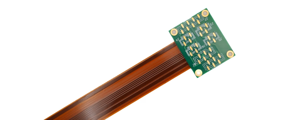
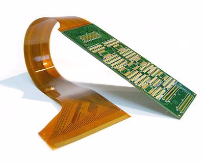
Rigid-flex PCB combines robust, high-density component mounting capabilities of rigid PCBs with the flexibility and dynamic bending features of flexible PCBs.
Get Your PCB Quote!
Table of Contents
1. Introduction: Bridging the Gap
In the dynamic landscape of modern electronics, miniaturization, performance, and reliability are paramount. Traditional rigid printed circuit boards (PCBs) offer robust support and component density, while flexible circuits excel in space-constrained, dynamic applications. However, many advanced products demand the best of both worlds. This is where rigid-flex PCB emerges as a revolutionary solution, seamlessly integrating rigid and flexible circuit technologies into a single, cohesive unit. These innovative rigid flex circuit boards are transforming product design, offering unparalleled design freedom and enhanced performance across diverse sectors, from aerospace to medical devices.
2. What are Rigid-Flex PCBs?
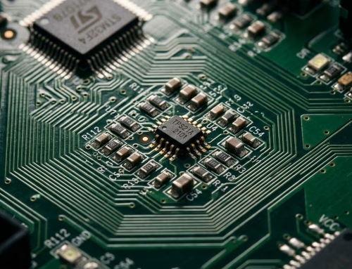
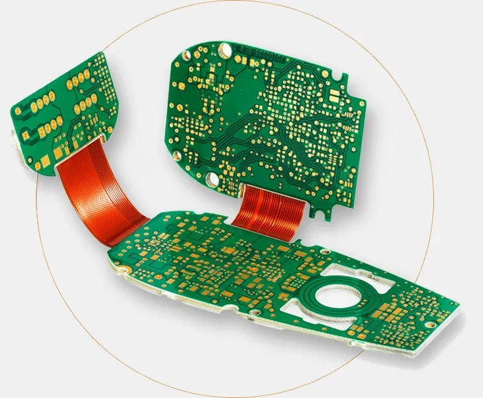
A rigid-flex PCB is a hybrid circuit board that combines the robust, high-density component mounting capabilities of rigid PCBs with the flexibility and dynamic bending characteristics of flexible circuits. Unlike simply connecting separate rigid and flex boards with cables, a rigid flex printed circuit board is an integrated structure where the flexible layers extend into the rigid areas. This creates a single, continuous electrical path, eliminating the need for connectors, cables, and other interconnects between the rigid and flexible sections. The result is a more compact, lightweight, and reliable electronic assembly.
3. The Unrivaled Advantages of Rigid-Flex Technology
The integration of rigid and flexible elements in rigid and flex PCB designs offers a multitude of benefits:
- Space and Weight Reduction:By enabling 3D interconnects and eliminating bulky cables and connectors, flexible rigid PCBs significantly reduce overall product size and weight. This is critical for portable devices, wearables, and aerospace applications.
- Enhanced Reliability:The single, integrated structure minimizes points of failure associated with connectors, solder joints, and wiring harnesses. This leads to higher resistance to vibrations and shocks, improving the overall lifespan of the electronic device.
- Improved Signal Integrity:Shorter signal paths and controlled impedance in the flex sections reduce noise and crosstalk, ensuring better signal transmission, especially crucial for high-speed applications.
- Simplified Assembly:Rigid flex PCBs consolidate multiple boards and interconnects into one unit, streamlining the assembly process, reducing labor costs, and decreasing the likelihood of manual wiring errors.
- Superior Thermal Management:The thin, flexible sections can dissipate heat more efficiently than traditional wiring, and their design allows for better airflow, contributing to improved thermal performance.
- Increased Design Freedom:Designers can create complex shapes and three-dimensional configurations, allowing for innovative product forms and optimized use of internal space.
- Reduced Logistics and BOM:Fewer components to manage translates to simpler inventory, reduced purchasing complexity, and often a lower Bill of Materials (BOM) cost despite a higher per-unit PCB cost.
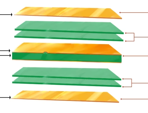
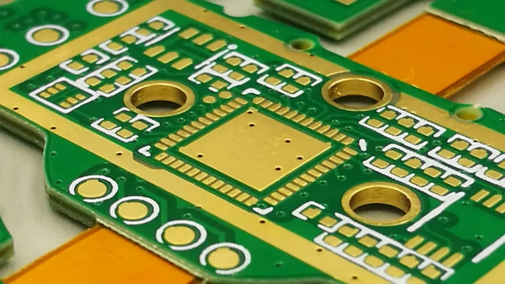
4. Construction and Layer Stack-Up
The construction of a rigid-flex PCB is a sophisticated process involving multiple layers of both rigid and flexible materials. Key components include:
- Flexible Substrate:Typically polyimide (PI) film, known for its excellent thermal stability, dielectric properties, and mechanical strength.
- Rigid Substrate:Usually FR-4 (fiberglass reinforced epoxy laminate), providing structural integrity and support for components. Other materials like high-Tg laminates may be used for specific thermal requirements.
- Adhesives:Specialized bond-ply or adhesive layers (often epoxy or acrylic-based) are used to laminate the flexible layers together and to bond the flexible and rigid sections.
- Copper Traces:Form the conductive pathways on both rigid and flexible layers.
- Coverlay/Solder Mask:Polyimide coverlay protects the flexible circuit traces, while solder mask protects the rigid sections and defines solderable areas.
The stack-up can vary significantly based on design complexity, ranging from simple two-layer rigid-flex to highly complex multi-layer structures.
5. Types of Rigid-Flex PCBs
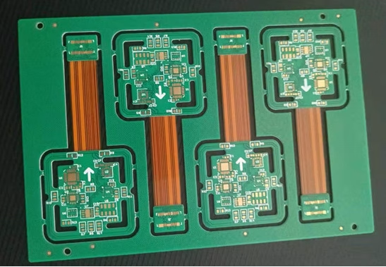
Rigid-flex designs come in various configurations, each suited for different applications:
- 2-Layer Rigid-Flex:The most basic type, often featuring one rigid layer and one flexible layer, or two flexible layers sandwiched between rigid sections.
- Multi-Layer Rigid-Flex:Involves multiple rigid and flexible layers, offering higher circuit density and complex routing capabilities.
- Rigid-Flex-Rigid PCB:A common configuration where a flexible section connects two or more rigid boards. This is ideal for applications requiring multiple component-dense areas connected by a flexible “bridge”.
- Single-Sided Flex with Rigid:A single flexible layer attached to a rigid board.
- Double-Sided Flex with Rigid:Two conductive layers on the flexible section, connected by plated through-holes, integrated with rigid sections.
6. Key Design Considerations for Rigid-Flex Circuits
Designing a rigid-flex circuit board requires careful attention to specific parameters to ensure functionality and manufacturability:
- Bend Radius and Dynamics:A critical factor. The minimum bend radius must be respected to prevent damage to the flexible traces. For dynamic applications (where the flex section moves repeatedly), specific materials and designs (e.g., larger bend radius, specific copper trace patterns) are required.
- Material Selection:Choosing the right polyimide type, adhesive, and FR-4 laminate is crucial for performance, thermal properties, and mechanical stress.
- Impedance Control:Maintaining consistent impedance, especially in high-speed signal paths, is vital. This requires precise control over trace width, dielectric thickness, and ground plane design.
- Trace Routing:Traces in the flexible sections should be routed perpendicular to the bend line, if possible, to distribute stress evenly. Avoid sharp corners; use teardrops for pads.
- Via Placement:Vias should be placed strategically, preferably in rigid areas, to maintain structural integrity. If in flex areas, they require careful design and manufacturing.
- Pad and Annular Ring Design:Pads on flexible layers often require larger annular rings or specialized pad designs (e.g., anchored pads) for robust connections.
- Thermal Management:Consider heat dissipation, especially in rigid areas with high-power components, and ensure the flexible sections can withstand operational temperatures.
- Layer Transition:The interface between rigid and flexible sections is a critical stress point and must be designed with appropriate stress relief features.
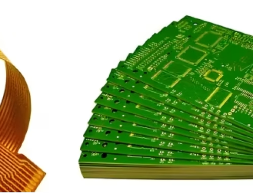
7. The Manufacturing Process of Rigid-Flex PCB
The manufacturing of rigid flex PCBs is more complex than conventional rigid boards due to the integration of disparate materials and processes. Key steps include:
1) Flexible Circuit Fabrication: The flexible layers are processed first, including lamination, drilling, etching, and applying coverlay.
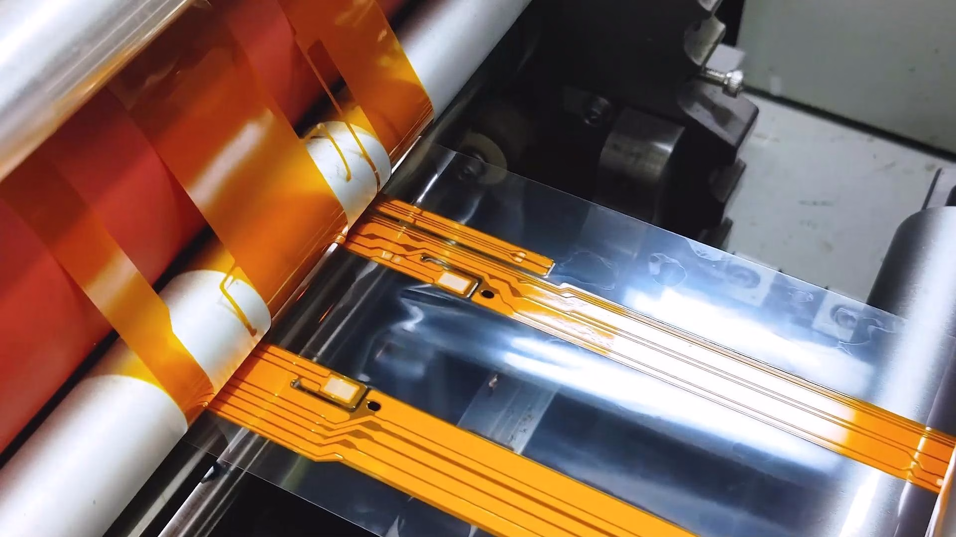
2) Rigid Layer Fabrication: Similar processes for the rigid sections.
3) Lamination: The rigid and flexible layers are bonded together using heat and pressure with specialized adhesives. This is a critical step, ensuring strong adhesion and precise alignment.
4) Drilling and Plating: Holes are drilled through the laminated stack, and then plated with copper to form conductive vias, connecting different layers.
5) Etching: Unwanted copper is removed to define the circuit traces.
6) Solder Mask Application: Applied to rigid areas.
7) Surface Finish: Various finishes (e.g., ENIG, HASL) are applied to ensure solderability.
8) Routing and Profiling: The final board shape is cut, often using a combination of routing and laser cutting, particularly for precise flex contours.
9) Testing: Electrical testing (e.g., flying probe, bare board test) ensures all connections are correct and there are no shorts or opens.
8. Diverse Applications Across Industries
The unique combination of rigidity and flexibility makes rigid-flex circuit boards ideal for a wide array of demanding applications:
1) Medical Devices: Implants, diagnostic equipment, wearables, and surgical tools benefit from their compactness, reliability, and ability to conform to irregular spaces.
2) Aerospace and Defense: Avionic systems, satellites, drones, and military equipment leverage the weight reduction, shock resistance, and thermal performance.
3) Automotive: Advanced driver-assistance systems (ADAS), infotainment, LED lighting, and engine control units utilize rigid-flex PCBs for their robustness and space efficiency.
4) Consumer Electronics: Smartphones, cameras, laptops, smartwatches, and virtual reality headsets rely on rigid-flex for miniaturization and enhanced durability.
5) Industrial Equipment: Robotics, automation controls, and test & measurement devices benefit from improved reliability in harsh environments.
9. Understanding Rigid-Flex PCB Cost Factors
The rigid flex PCB cost is generally higher than traditional rigid or pure flexible PCBs due to the specialized materials, complex manufacturing processes, and design expertise required. Several factors influence the final price:
| Factor | Impact on Cost | Description |
| Complexity of Design | High | Number of layers (especially flexible ones), fine lines/spaces, controlled impedance requirements, intricate shapes, and tight tolerances increase cost. |
| Material Selection | Medium to High | Specialized polyimide films, high-performance laminates, and specific adhesives are more expensive than standard FR-4. |
| Panel Utilization | Medium | Irregular shapes and inefficient panel layouts can lead to material waste, increasing per-unit cost. |
| Volume | Low (for high volume) | As with most PCBs, higher production volumes generally lead to lower per-unit costs due to economies of scale. |
| Turnaround Time | High (for quick turn) | Quick turn rigid flex PCB orders often incur premium charges due to expedited processing and specialized scheduling. |
| Testing Requirements | Medium | More stringent electrical or functional testing adds to the manufacturing time and cost. |
While the initial cost may be higher, the long-term benefits in terms of reliability, reduced assembly, and overall system cost often justify the investment.
10. Choosing a Reliable Rigid-Flex PCB Supplier
Selecting the right flex rigid PCB manufacturer or rigid flex PCB supplier is crucial for success. Consider the following:
- Experience:Look for manufacturers with proven expertise in rigid-flex technology, not just standard PCBs.
- Capabilities:Ensure they can handle your specific design requirements (e.g., layer count, material types, tight tolerances, dynamic bending).
- Quality Certifications:Check for industry standards like ISO 9001, AS9100 (for aerospace), and medical device quality standards.
- Customer Support:A responsive and knowledgeable engineering support team is invaluable for complex rigid-flex designs.
- Lead Times:For quick turn rigid flex PCB needs, verify their ability to meet aggressive schedules without compromising quality.
- Cost-Effectiveness:While not the cheapest option, ensure they offer competitive pricing relative to their capabilities and quality.
11. Rigid-Flex PCB FAQs
A rigid-flex PCB is a single, integrated unit with continuous electrical connections between rigid and flexible sections, eliminating the need for connectors, cables, and manual assembly. This offers higher reliability, smaller form factor, and better signal integrity compared to separate boards connected by external means.
Generally, yes. The specialized materials, more intricate manufacturing processes, and design expertise required for rigid-flex PCBs typically lead to a higher per-unit cost compared to conventional rigid boards. However, they often lead to overall system cost savings by reducing assembly time, materials (connectors, cables), and improving reliability.
The rigid-flex-rigid PCB configuration is common in applications where multiple component-dense rigid sections need to be connected by a flexible bridge. This is ideal for devices requiring 3D assembly, such as cameras, medical implants, laptops, or any product where space is limited and multiple sub-assemblies need compact, reliable interconnection.
The most critical consideration is the bend radius and the type of bending (static vs. dynamic). Respecting the minimum bend radius prevents trace damage, while dynamic applications require specific material choices and trace routing to ensure longevity and prevent fatigue.
Yes, many rigid flex PCB manufacturer(like PcbAndAssembly) offer quick turn rigid flex PCB services, though they may come with a premium. It’s essential to communicate your timeline and design requirements clearly with your rigid flex PCB supplier to ensure they can meet your expedited needs.
12. Summary
As electronic devices continue to shrink while demanding greater functionality and reliability, rigid-flex PCBs have become an indispensable technology. By masterfully blending the structural integrity of rigid boards with the adaptable nature of flexible circuits, they offer an elegant solution to complex design challenges. From optimizing space and weight to enhancing electrical performance and streamlining assembly, the advantages of these rigid flex circuit boards are profound. Understanding their construction, design nuances, and manufacturing considerations is key to harnessing their full potential.
Key Takeaways
- Rigid-flex PCBsare hybrid circuits integrating rigid and flexible substrates into a single, cohesive unit.
- They offer significant benefits in space/weight reduction, reliability, signal integrity, and assembly simplification.
- Design considerations like bend radius, material selection, and trace routing are crucial for performance.
- Manufacturing is complex, involving specialized lamination and profiling techniques.
- Widely used in aerospace, medical, automotive, and consumer electronics for their versatility.
- Rigid flex PCBcost is influenced by complexity, materials, and volume, with quick turn rigid flex PCB options available at a premium.
- Selecting an experiencedflex rigid PCB manufacturer is vital for successful project execution.
Table of Contents

Get Your PCB Quote!