What Are PCB and PCBA? What Are the Differences Between Them?
Get Your PCB Quote!
Table of Contents
For individuals knowledgeable in the electronics field, this query should be simple to respond to. Nonetheless, for many novices or non-experts in the electronics sector, it can be simple to mix up and confuse PCBA with PCB.
I believe a lot of individuals are familiar with the terms circuit board, PC board, and PCB. Indeed, these three phrases convey the same idea. If you’ve gone through different financial books, newspapers, articles, and videos concerning stocks, you likely have encountered this term.
Nonetheless, if you are outside the electronics sector, you might not be familiar with the term PCBA and could wrongly connect it with PCB. While PCB and PCBA vary by just one letter, there are notable differences between them in the realm of electronics assembly manufacturing.
The upcoming section will explain these two terms and emphasize their distinctions.
What Are PCB, Circuit Board, and PC Board?
They are refer to the same thing. A printed circuit board, commonly referred to as PCB, is a crucial electronic component that serves as a support for electronic parts and facilitates circuit connections for these components. Due to its creation with electronic printing technology, it is referred to as a “printed” circuit board.
Prior to the introduction of printed circuit boards, the connection among electronic components relied on directly linking wires to create a complete circuit. Circuit panels served merely as useful experimental instruments, whereas printed circuit boards now hold a completely dominant position in the electronics sector. In the early 20th century, to make the production of electronic devices easier, decrease the wiring among electronic components, and lower manufacturing expenses, individuals started exploring the technique of substituting wiring with printing. For the last three decades, engineers have consistently suggested utilizing metal conductors for wiring on insulating materials. The most notable achievement occurred in 1925, when Charles Ducas from the United States created a circuit design on an insulating substrate and then effectively formed conductors for wiring through electroplating.
The manufacturing process of printed circuit boards (PCBs) resembles how early book pages were produced. Usually, we utilize something referred to as film. I’m uncertain whether you have ever come across early physical slides. We would replicate or manually sketch text and images on a transparent plastic sheet and then use light to project it onto a white wall or screen.
In PCB manufacturing, the negative of the circuit design is initially printed onto the film, followed by using an exposure machine to project the areas without circuits onto the copper foil substrate. The surplus copper foil is subsequently eliminated through chemical etching, retaining only the essential copper foil circuit.
Multilayer PCBs are made in a comparable manner, layering etched copper foil substrates one on top of the other. Nonetheless, as technology progresses, the manufacturing of printed circuit boards has grown more intricate and advanced; however, the printing process technologies and methods remain widely used.
The reason contemporary electronic devices possess numerous functions is that they are essentially composed of electronic circuits and components, which need a substrate, and PCB serves as this substrate.
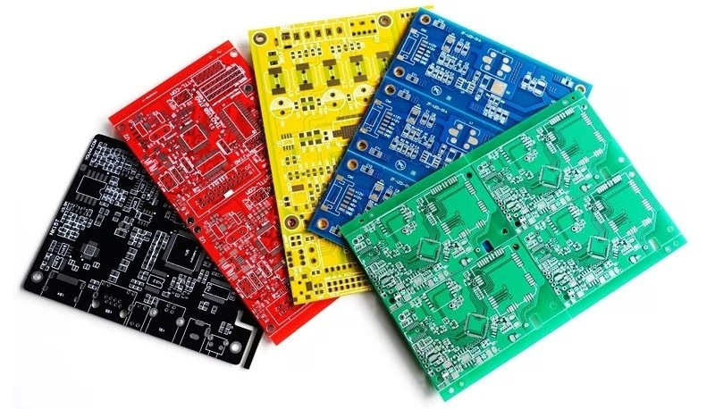
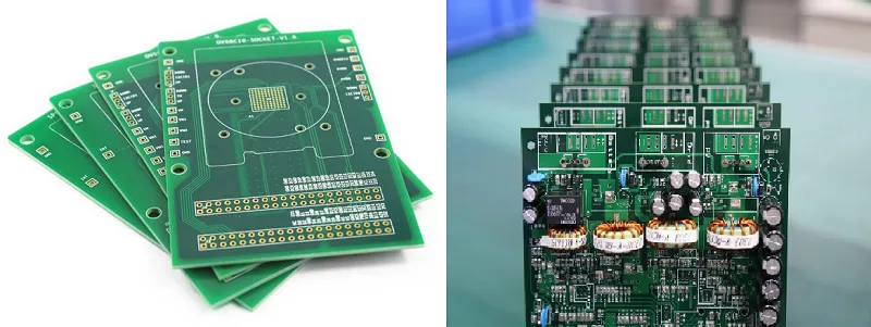
PCB is an empty circuit board filled with circuits. The circuit board is referred to as PCBA only once all electronic components have been installed on it.
We typically call a PCB that has printed electronic circuits but no assembled components a blank board, bare board, or just a bare board to differentiate it from a PCBA.
From a technical perspective, PCB should be seen as one of the elements of PCBA. It is an essential part of electronic devices. It serves as the foundational framework for electronic components and acts as the conduit for electrical connections among these components.
Certainly, there exists another kind of FPC known as a flexible printed circuit board, which serves the same carrier purpose as PCB; nonetheless, the requirements and uses for rigid and flexible types differ. In numerous electronic product designs, rigid board PCBs remain the primary application.
In simple terms, PCB is the key component of the electronics industry, and nearly all electronic devices depend on it. Nonetheless, the PCB production process includes electroplating activities that demand significant amounts of water and electricity, potentially leading to water contamination. As environmental awareness has grown, expenses have also considerably increased.
PCB Is Extensively Utilized in Electronics and Possesses Distinct Features and Benefits
• Enhanced wiring density, smaller dimensions, and decreased weight have aided in the miniaturization of electronic devices. As technology progresses and the demand increases for sleeker, smaller, and more functional electronic gadgets, PCB processing equipment has recently transitioned to early integrated circuit technologies, with certain processes slowly incorporating semiconductor machinery.
• Strong repeatability and uniformity. It can be manufactured in large quantities to guarantee uniformity and reliability, reducing the issue of errors in cable wiring assembly, while the modular structure can shorten the duration needed for equipment upkeep, diagnostics, and evaluation.
• Automated production. At present, PCB and PCBA can be nearly entirely automated, leading to lower labor costs and fewer operational mistakes, enhancing worker productivity, and aiding in reducing product prices and expanding market access.
• The design may be standardized or modular. If several functions are needed, simply replace the complete PCBA board.
So What Is PCBA?
PCBA stands for Printed Circuit Board Assembly, referring to the complete procedure of a bare PCB being subjected to SMT assembly or DIP plug-in.
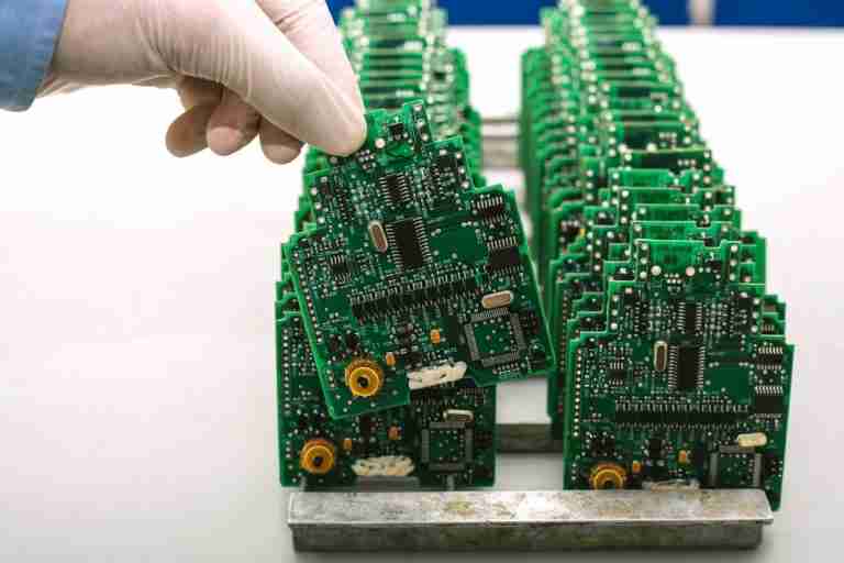
The distinction between PCB and PCBA is as follows: PCBA = PCB + Assembly. In other words, a circuit board lacking electronic parts is referred to as a PCB, while one that includes electronic components is known as a PCBA. PCBA refers to the process where electronic components are attached to the PCB following a specific circuit diagram through soldering and other techniques, resulting in a circuit board assembly with designated functions.
The proper term for PCBA is Printed Circuit Board Assembly, also called PCB Assembly. Some individuals refer to it as PCA, whereas others refer to it as PWA (Printed Wire Assembly).
Typically, when a machine contains just one circuit board, we refer to it as the motherboard or just the circuit board. If the device contains over two PCBAs, we will categorize them based on their functions, referring to them as the motherboard, IO board, charging board, and display board.
PCBA is a crucial part of electronic products, and its functionality directly impacts the performance and reliability of the whole electronic products.
In What Manner Are Electronic Parts Organized on a PCB to Create a PCBA?
PCBA consists of PCB, electronic components, solder joints, and more. Electronic components are linked to the circuit layout on the PCB via soldering and other techniques, creating a complete circuit system.
The most widely used PCB assembly technique is SMT (Surface Mount Technology), which initially applies solder paste to the unpopulated board, then attaches the electronic components to the PCB, and finally places it in a reflow oven. The elevated temperature melts the solder paste, linking the component pins to the PCB, securing the component and creating an electronic link between the component and the PCB.
SMT (Surface Mount Technology)
Surface mount technology primarily employs a mounter to place small components onto the PCB. The process of production involves: PCB alignment, solder paste application, component placement by mounters, reflow oven processing, and final inspection. As technology advances, SMT is capable of placing larger components, including bigger mechanical parts, onto the motherboard.
SMT integration is highly affected by the positioning and size of components. Furthermore, the quality of solder paste and the printing quality are also crucial factors.
In PCBA assembly, a minimal quantity of wave soldering technique is utilized. Typically, certain electronic components on the assembly board are heavy, must endure external forces, and require frequent plugging and unplugging.
If these parts cannot be entirely transformed into SMD components for technical reasons, or if the expense of SMD components doesn’t satisfy market needs, or if some components must endure frequent plugging and unplugging stresses during use by end-users, they will instead be designed as through-hole components, known as plug-ins (THD, Through Hole Devices), and will then go through a wave soldering furnace to secure the components to the PCB’s through holes.
DIP (Dual In-Line Package)
DIP stands for “dual in-line package”, referring to the addition of components on the PCB. When the components are large and unsuitable for mounting, or if the manufacturer’s production method cannot utilize SMT technology, the components are assembled in a plug-in format. In the industry, there are two methods of implementation: manual plug-in and robotic plug-in. The primary production steps involve: applying adhesive backing (to stop tin plating from reaching unwanted areas), plugging in, inspecting, wave soldering, brushing (to eliminate marks left from the furnace process), and conducting a final inspection.
SMT and DIP are both methods for assembling components on PCB boards. The key distinction is that SMT does not need holes drilled in the PCB, whereas DIP necessitates that the component’s PIN pins be placed into the pre-drilled holes.
Certain designs integrate SMT (surface mount technology) with wave soldering to attach components to the PCB. In conclusion, numerous technologies are available for attaching electronic components to a PCB.
Trend of PCBA Development
• Strongly advance high-density interconnect technology (HDI): HDI represents the latest technology in modern PCBs, introducing narrow conductors and small holes in PCBs.
• Component embedding technology with significant potential: Component embedding technology represents a major transformation in PCB functional integrated circuits. PCB manufacturers need to boost resource allocation in areas such as design, equipment, testing, and simulation to sustain robust vitality.
• PCB materials that comply with global standards: excellent heat resistance, elevated glass transition temperature (Tg), low thermal expansion coefficient, and minimal dielectric constant.
• Transition to halogen-free: As global environmental awareness has increased, prioritizing energy conservation and emission reduction has become essential for both national and corporate growth. Given their elevated pollutant emission levels, PCB companies ought to be significant contributors and active participants in energy conservation and emission reduction efforts.
• Create new resin formulations: including waterborne epoxy substances to lessen solvent impact; derive resins from sustainable sources like plants or microorganisms to minimize the reliance on oil-based resins.
• Seek substitute materials to lead-based solder: Create novel, reusable sealing substances to guarantee the recyclability of devices and packages, facilitating disassembly.
Summary
From the introduction above, everyone should have a clear understanding of what PCB means and what PCBA represents.
A PCBA can essentially be regarded as a finished product, as certain manufacturers will produce a PCBA and ship it directly, like those that offer computer motherboards or standalone graphics cards.
PCB can essentially be viewed as a component. PCB is an essential component of the whole PCBA, yet it does not completely represent PCBA. This is due to the fact that integrated circuits, resistors, capacitors, inductors, connectors, and various other components must be soldered onto the PCB to create the finished product. Consequently, PCB should be considered merely as a component.
PCB and PCBA differ greatly in definition, function, manufacturing process, and application.
PCB serves as the foundation and support for electronic components, whereas PCBA refers to a circuit board assembly designed for particular functions, which directly influences the performance and capabilities of electronic products.
In the electronics production sector, PCB and PCBA are essential components.
Table of Contents
Get Your PCB Quote!
