FR4 PCB Material Guide: Properties, Types, and Applications
FR4 is the most common PCB base material, offering strength, insulation, and flame resistance. Learn FR4 and how to choose the right FR4 for PCB design.
Get Your PCB Quote!
1. What is FR4?
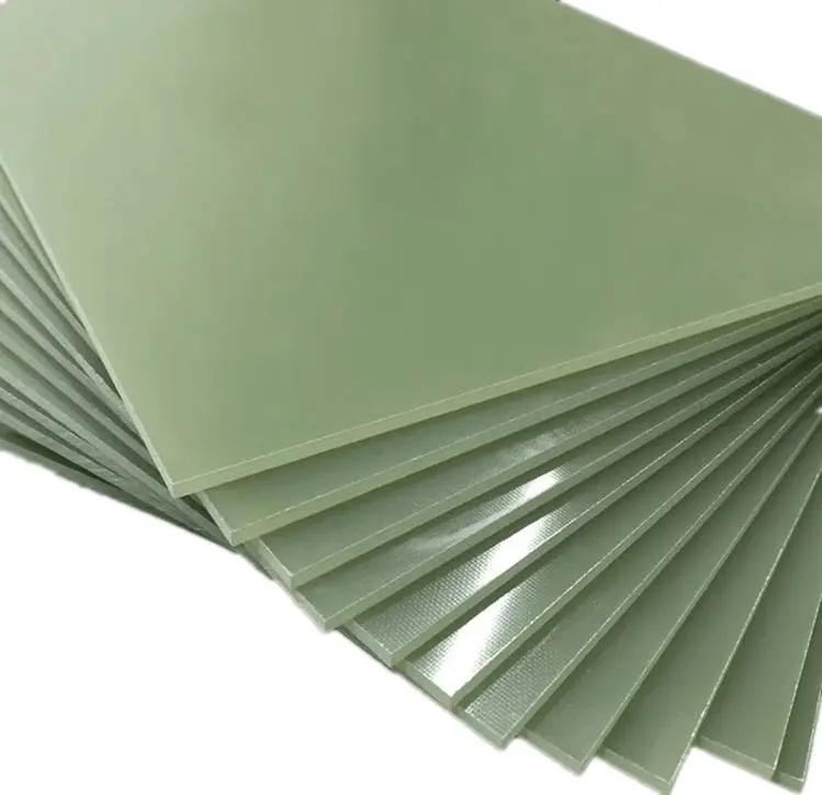
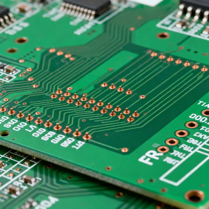
FR4 is a composite made up of woven glass fiber fabric bound together with an epoxy resin adhesive. It ranks among the most widely used substrate materials (i.e., base materials) for printed circuit boards (PCBs). Here, “FR” denotes “flame retardant,” while the “4” represents the material’s classification code for flame-resistant properties.
2. What is the use of FR4 in the PCB Industry
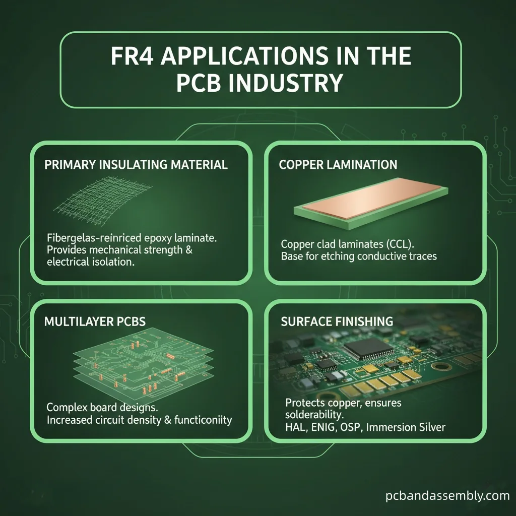
1) Primary Insulating Materials
Within PCBs, FR4 acts as the primary insulating substrate—it provides a solid base to hold up the copper traces that make up the actual circuits. This fiberglass-reinforced epoxy laminate boasts high mechanical strength and excellent electrical insulation—both of which are critical to ensuring reliable PCB performance.
2) Copper Lamination
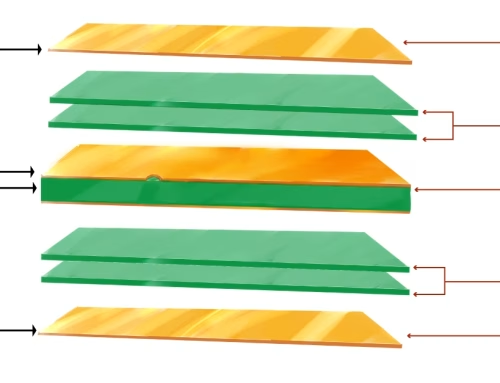
FR4 sheets are bonded with one or more copper foil layers via lamination. In order to create a strong bond between the copper and the FR4 substrate, this procedure uses heat and adhesive. After that, the copper layers are etched to provide the required circuit designs. PCBs that are single-sided, double-sided, or multilayer can be produced using this manufacturing technique.
3) Multilayer PCBs
FR4 and copper are laminated in many layers, separated by insulating prepreg (pre-impregnated) layers. This facilitates the creation of intricate, high-density circuits capable of supporting advanced modern electronic devices. For those seeking an HDI PCB manufacturer to fulfill the advanced needs of such systems, High Tg FR4 stands as an ideal option for your upcoming project.
4) Surface Finishing
When the copper layers are done being etched, a protective solder mask is applied to the PCB to fend off oxidation and solder bridges in the course of assembly. HASL (Hot Air Solder Leveling), ENIG (Electroless Nickel Immersion Gold), and OSP (Organic Solderability Preservatives) are examples of common surface treatments.
3. How do various FR4 material types differ from one another?
1) Standard FR4
Standard FR4 is the most widely used material, with a good balance of mechanical, electrical, and thermal characteristics. Its glass transition temperature (Tg) is approximately between 130°C and 140°C, a trait that makes it suitable for general-application scenarios requiring moderate heat resistance.
2) G10
G10 stands out for its toughness, high thermal shock resistance, and superior electrical insulating performance. It is used in applications requiring a solid core with strong mechanical and dielectric properties. A key distinction is that FR4 is flame-retardant, while G10 is not.
3) FR4 without Copper Laminate
This FR4 kind is mostly utilized for mechanical supports and insulating boards because it lacks a copper layer. It retains all the mechanical strengths of standard FR4 while being non-conductive.
4) High Tg
High Tg FR4 is developed for high-temperature settings, characterized by a higher glass transition temperature—generally falling between 170°C and 180°C. This version stands out in high-power and high-reliability applications such as automotive systems and power electronics; in these scenarios, the material must preserve its characteristics under elevated temperatures. If you need to find a High Tg FR4 PCB manufacturer that produces high-quality, reliable PCBs for these rigorous applications, we can satisfy your needs.
5) High-Frequency FR4
High-frequency FR4 materials are optimized specifically for radio frequency (RF) and microwave use cases. Their features, such as a lower dielectric constant and dissipation factor, aid in lowering signal attenuation and enhancing signal integrity at high frequencies. Such high-frequency FR4 materials are often employed in telecommunications, aerospace, and radar systems.
6) High-CTI FR4
High CTI FR4 materials (short for High Comparative Tracking Index FR4) deliver the highest resistance to electrical breakdown and boast enhanced thermal conductivity. They excel as a choice for scenarios needing rapid heat dissipation and strong electrical insulation, including power supplies and industrial electronic devices.
4. What is the FR4 Substrate’s Properties?
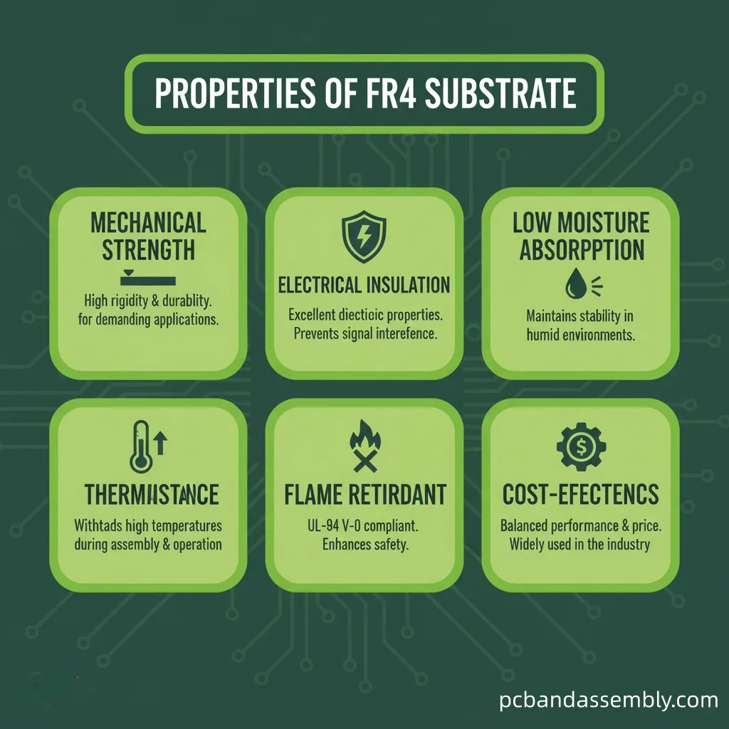
FR4 substrates are characterized by important properties, which make them ideal for a variety of electronic applications.
- Mechanical Strength:FR4 substrates stand out for their strong mechanical strength, a trait that preserves durability and resilience against physical stresses in both manufacturing and application processes.
- Electrical Insulation:FR4 delivers superior electrical insulation—a trait that helps ward off electrical shorts while ensuring reliable operation of circuits.
- Low Moisture Absorption: Its low moisture absorption allows FR4 to maintain stable electrical and mechanical properties even in humid environments.
- Thermal Resistance: FR4 excels at withstanding high temperatures, notably making it suitable for scenarios where heat dissipation is a key requirement.
- Flame Retardant: FR4 is characterized as a flame-retardant material—it minimizes the risk of fire, which in turn enhances the safety of electronic devices.
- Cost-Effectiveness: Compared to other high-performance PCB materials, FR4 is relatively cost-effective.
5. Types and Applications of Dielectric Material
The two primary types of dielectric materials are active and passive.
1) Active Dielectrics
Active dielectrics enable the control of electrical behavior within circuits. Able to modify and manage the operation of electrical signals, they prove valuable for components including capacitors and transistors. These dielectrics play a significant role in tuning circuits while enhancing signal processing.
2) Passive Dielectrics
Passive dielectrics provide insulation and mechanical support—with no impact on electrical signals—and are used to prevent electrical shorts and shield components. By acting as barriers between conductive parts, they also maintain circuit integrity.
6. Dielectric Properties Of FR4
Within FR4 circuit boards, the dielectric constant—known as Dk—quantifies a material’s capacity to store electrical energy within an electric field. When it comes to PCBs, Dk has an impact on how fast electrical signals propagate through the material. A stable dielectric constant is vital for preserving signal integrity—this is especially true in high-frequency applications, as it ensures consistent signal propagation and reduces signal loss.
Dielectric dissipation—otherwise called loss tangent (Df)—quantifies the energy that is lost as heat. For FR4 materials, a low Df is desirable; a higher Df can result in both signal attenuation and noise, which negatively impacts overall PCB performance.
Expressed in volts per unit thickness, dielectric strength denotes the maximum electric field a dielectric is capable of withstanding prior to experiencing breakdown or turning conductive.
6.1 Typical Dielectric Constant Values for FR4
The dielectric constant (Dk) of an FR4 PCB ranges roughly from 3.9 to 4.8, though minor variations may occur—driven by the specific formulation and manufacturing process. This Dk Value’s Impacts:
- Signal Speed:A higher dielectric constant slows down the propagation speed of electrical signals—and this factor must be considered by designers during the design of high-speed circuits.
- Impedance Control:Transmission lines’ impedance on the PCB is influenced by the dielectric constant. Maintaining the appropriate impedance levels, which is essential for guaranteeing signal integrity in high-speed and high-frequency applications, is made easier by consistent Dk values..
- Capacitance: The dielectric constant exerts an influence on the capacitance values between conductors on the PCB.
- Propagation Delay: For materials with higher dielectric constants, they result in increased propagation delays—which subsequently affects the timing of how signals are transmitted.
- Signal Integrity: Variability in the dielectric constant (Dk) can give rise to signal distortion and attenuation—most notably in high-frequency application scenarios.
- Loss Tangent:Higher dielectric constants often correspond to higher loss tangents, meaning more energy is dissipated as heat and overall efficiency is reduced.
- Crosstalk:For high-speed digital applications, a higher Dk can raise crosstalk between adjacent traces—which in turn degrades signal quality and may cause errors.
- Electromagnetic Interference (EMI):Higher dielectric constants can result in greater electromagnetic interference (EMI)—and this in turn can disrupt how nearby electronic devices and systems perform.
6.2 Factors Affecting Dielectric Constant

1) Resin Composition
The specific epoxy resin system in FR4 has a significant impact on its dielectric constant (Dk). Given differences in resin formulations, slight variations in Dk values can arise across manufacturers; furthermore, the resin type also affects the overall electrical performance of FR4 materials.
2) Filler Composition
The dielectric properties of FR4 are dependent on the filler loading in the epoxy resin: greater filler percentages generally elevate the Dk of the FR4 composite. Furthermore, various filler types used in the resin can modify the material’s thermal and mechanical properties, which subsequently affect the substrate’s overall performance.
3) Frequency
Because of polarizability effects, the dielectric constant of FR4 decreases as frequency rises—and across the 1 MHz to 10 GHz frequency range, a 10–20% reduction in Dk is typically observed. This change is critical for high-frequency applications, in which precise control of signal integrity is a key requirement.
4) Fiberglass Weave
The glass fabric weave structure within the laminate can induce minor dielectric constant anisotropies. Such subtle discrepancies are critical in high-precision applications, as they have the potential to compromise the electrical performance uniformity across the entire PCB.
5) Moisture Absorption
Moisture raises the dielectric constant of FR4, as water itself has a very high Dk. This is a big concern in humid places: the moisture a PCB absorbs can hurt its electrical properties, which in turn harms its performance and reliability. Using proper sealing and protective coatings can help reduce this problem.
6) Temperature
Because increased molecular motion causes the dielectric constant of FR4 to decline linearly as temperature rises, it exhibits a negative temperature coefficient. Specifically, higher temperatures intensify the thermal motion of molecules in the material, which diminishes their polarization and ultimately lowers the dielectric constant. This effect must be addressed to maintain signal integrity under varying thermal conditions.
7) Lamina Thickness
Depending on the proportions of glass, resin, and air, the composite dielectric constant can be altered by the quantity and thickness of laminate sheets. Thicker laminates may have different dielectric properties than thinner ones, because their structural composition varies.
7. What are FR4’s thermal characteristics?
Glass Transition Temperature (Tg)
The precise temperature at which FR4 changes from a stiff to a more flexible form is known as the glass transition temperature (Tg).In addition to defining the PCB’s maximum operating temperature, the glass transition temperature (Tg) of FR4 normally falls between 130°C and 180°C. Exceeding this temperature can also deteriorate the material’s mechanical and electrical qualities, which may result in PCB failure.
Coefficient of Thermal Expansion (CTE)
For FR4, the coefficient of thermal expansion (CTE) is defined as a parameter that measures the extent of its expansion when exposed to temperature fluctuations. Below Tg, the CTE is low; however, it increases significantly once the temperature exceeds Tg. High CTE values can produce mechanical stress, which affects vias and solder joints—especially in high-temperature environments.
Thermal Conductivity
FR4 has low thermal conductivity, generally ranging from 0.25 to 0.4 W/m·K. This low conductivity means the material dissipates heat poorly, which may create hotspots and compromise component performance. For FR4 PCBs, effective thermal management (such as using heat sinks and thermal vias) is a key measure to control heat buildup.
8. Mechanical properties of FR4
Tensile Strength: FR4 exhibits a tensile strength of roughly 70,000 psi, alongside excellent mechanical durability and resistance to tensile fracture under tensile loading. This high mechanical strength renders FR4 well-suited for applications where mechanical stress is a key consideration.
Flexural Strength: With a flexural strength also around 70,000 psi, FR4 has the ability to withstand considerable bending without sustaining cracks.This property helps preserve PCB integrity when exposed to mechanical stress.
Impact Resistance: FR4 exhibits superior impact resistance, facilitating shock and impact absorption while minimizing resultant damage. Based on its design parameters, this renders it applicable to scenarios prone to physical impacts or vibrational forces.
Dimensional Stability: FR4 keeps its shape and size even when temperature and humidity change, and it offers great dimensional stability.
9. How Do FR4 and Rogers Materials Differ From One Another?
| FR4 | Rogers Material | |
| Composition | Woven fiberglass cloth with epoxy resin binder | Thermoset ceramic-filled PTFE composite |
| Dielectric Constant (Dk) | 4.2 to 4.6 | 2.2 to 10.2 |
| Dissipation Factor (Df) | 0.02 to 0.03 | 0.0009 to 0.002 |
| Thermal Conductivity Performance | The material can withstand temperatures up to 266°F (130°C). | This material can tolerate temperatures up to 536°F (280°C). |
| Moisture Absorption | Higher absorption rates of 0.1 and 0.2% | Lower absorption rates of 0.02 to 0.08% |
| Advantages | 1. Affordable
2. Widely available 3. Versatile 4. Good mechanical strength 5. Flame resistant 6. Suitable for various PCB types (single, double-sided, multilayer) |
1. High-frequency performance
2. Low signal loss 3. Stability under temperature variations 4. Wide dielectric constant range |
| Disadvantages | · Higher signal loss at high frequencies
· Lower thermal conductivity |
· Fabrication complexity
· Higher cost |
| Applications | · Consumer electronics
· Industrial controls · Automotive electronics |
· Microwave point-to-point
· Automotive radar and sensors · Military and aerospace · High-frequency communication |
| Cost | Cost-effective | Higher cost |
10. Advice on Choosing the Best FR4 Material
During FR4 PCB manufacturing, material selection is crucial for producing a functional circuit board. Below are the key considerations recommended by PCBAndAssembly experts when choosing the right material:
- Operating Temperature:For high-temperature applications (with temperatures reaching 170°C or higher), opt for high Tg (glass transition temperature) FR4.
- Thickness Requirements:Choose the right thickness based on what the application needs for rigidity or flexibility.
- Electrical Performance:For high-frequency applications (e.g., RF circuits, 5G signal transmission), select low-loss FR4 substrates. Low dielectric constant (Dk) and low dissipation factor (Df), two essential characteristics for reducing signal attenuation in high-speed signal transmission, are present in these substrates.
- Moisture Resistance:For humid environments, ensure the FR4 PCB material chosen has strong moisture resistance to maintain its structural integrity and performance.
- Mechanical Properties:Choose FR4 that can withstand mechanical stresses such as flexing, drilling, and thermal expansion.
- Environmental Impact:Select eco-friendly FR4 materials that meet relevant standards for flame retardancy and durability.
- Cost-Performance Balance:Balance cost and performance according to project needs: standard FR4 PCB base material is cost-effective, while specialized FR4 delivers higher performance but at a higher cost than the standard variant.
11. FR4 FAQs
1)What does the FR4 stand for?
FR4 is the industry-standard flame-retardant fiberglass-reinforced epoxy laminate material employed in the production of printed circuit boards (PCBs).
2) Why is FR4 used in PCB?
FR4 is commonly used in PCBs mainly because it has good electrical insulation, decent mechanical strength, and reliable heat resistance.
3) Is FR4 cheap?
FR4 boards are reasonably priced and effective for a wide range of applications.
4) Why is it called FR4?
The abbreviation “FR” stands for “flame retardant,” while the number “4” represents the material’s classification code for flame-resistant properties.
5) Can FR4 be recycled?
FR4 cannot be recycled back into its original constituent parts.
6) Does FR4 creep?
Under-rated conditions, G10/FR4 components typically exhibit less than 1% creep over decades.
Contact Us
FR4 (or FR – 4) is almost universally used in various PCBs, thanks to its combination of convenience, affordability, and ease of processing. However, a deep understanding of FR4’s material characteristics enables you to select the optimal material accurately during the PCB manufacturing process. PCBAndAssembly is here to provide design and manufacturing support for high – quality PCBs tailored to your specific application scenarios. Obtain an online PCB quotation immediately!

Get Your PCB Quote!