
Rogers PCB Manufacturing for High-Frequency Signal Integrity
Low-loss Rogers laminates, controlled impedance and engineered stack-ups for RF, microwave, antenna and high-speed digital applications.
What is Rogers PCB?
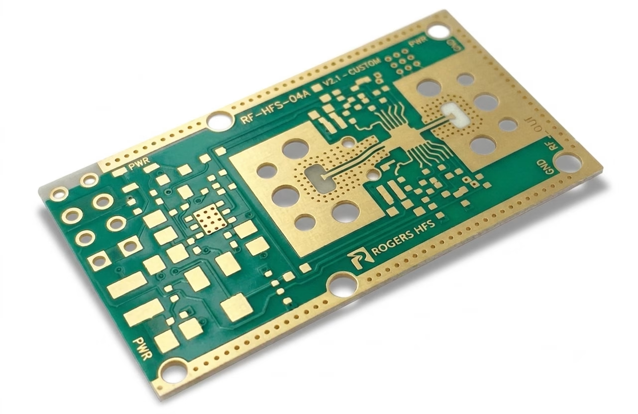
Rogers PCBs are printed circuit boards made from engineered Rogers circuit board material, specifically designed to minimize dielectric loss, support high-frequency operation, and provide stable electrical performance across a wide frequency range. OrinewPCB fabricates Rogers printed circuit boards to deliver superior performance for your most demanding applications.
- Rogers PCB fabrication with low-loss, low-moisture absorption substrates.
- Rogers material support for RF, radio frequency, and high-speed digital circuits.
- Tight DK and DF control with IPC-compliant performance and streamlined properties over traditional PCB materials.
Choose the Substrate Around
Your Signal, Not a Generic Material List
FR-4 remains practical for many standard digital circuits. Rogers becomes relevant when dielectric loss, Dk stability, controlled impedance, moisture behavior or thermal cycling drives the design.
Frequency and
Signal Path
Standard digital /
RF / Microwave /
Antenna
Loss Budget
Insertion loss /
signal margin /
dielectric loss
Construction
All-Rogers /
Rogers + FR-4
hybrid

Types of Rogers PCB Materials

Metal Claddings
- Rolled
- Electrodeposited
- Electrodeposited Reverse Treated
- Resistive Foil

Bonding Materials
- Ceramic PTFE Bondply
- Woven Glass
- Prepreg
- Hydrocarbon
- Thermoset Thermal and Electrically Conductive Adhesive (TECA) Film

Laminates
- Woven Glass Reinforced Modified Epoxy Laminates
- PTFE Random Glass Fiber
- Woven Glass UL 94 V-0 laminates
- Hydrocarbon
- PTFE Ceramic
- Cross-Plied Woven Glass-Reinforced PTFE
- Woven Glass Reinforced PTFE Antenna Grade Laminates
- Filled PTFE Composite
- Woven Glass Reinforced Modified Epoxy IMS

Advanced Rogers PCB materials from Our
- PTFE-based: RO3000 Series, RT Series
- Non-PTFE: RO4000 Series, Kappa 438
- Thermoset Ceramic-filled Resin: TMM Series
- Prepreg Types: RO4400 Series, 2929, RO1200
Select a Rogers Grade by Frequency, Loss Budget and Process
There is no single best Rogers material for every board. Grade selection depends on frequency, loss target, Dk, layer construction, assembly process, thermal environment and test requirements.
| Grade | Material family | Dk | Df / condition | Typical use | Selection signal |
| RO4003C | Hydrocarbon ceramic | 3.38 +/- 0.05 | 0.0027 @ 10 GHz | RF, microwave and high-speed builds | Balanced loss, Dk and process compatibility |
| RO4350B | Hydrocarbon ceramic | 3.48 +/- 0.05 | 0.0037 @ 10 GHz | RF, automotive and qualified lead-free builds | Thermal / assembly requirements and controlled impedance |
| RO3003 | Ceramic-filled PTFE | 3.00 +/- 0.04 | 0.0013 @ 10 GHz | Very low-loss RF, radar and antenna designs | Lower loss at microwave frequencies |
| RO3006 / RO3010 | High-Dk PTFE ceramic | 6.15 / 10.2 class | Confirm exact grade and method | Compact RF and microwave structures | Higher Dk for size reduction |
| RT/duroid 5880 | Glass microfiber PTFE | 2.20 | 0.0009 @ 10 GHz | Low-loss microwave and mmWave paths | Minimum loss and low-Dk construction |
Rogers vs FR-4: Where the Performance Difference Matters
FR-4 is a practical baseline for many general-purpose digital and lower-frequency designs. Rogers laminates are selected when loss, Dk stability, impedance or thermal behavior becomes a key design constraint.
| Property | Rogers PCB | FR4 |
| Dielectric Constant (Dk) | 2.2 to 10.2 | 4.3 to 4.8 |
| Dissipation Factor (Df) | 0.0009 to 0.003 (@10 GHz) | 0.020 to 0.027 (@1 MHz) |
| Moisture Absorption | <0.1% | 0.10% to 0.25% |
| Z-Axis CTE | 10 to 17 ppm/°C | 40 to 70 ppm/°C |
| Thermal Conductivity | 0.5 to 2.0 W/m·K | ~0.25 W/m·K |
| Glass Transition Temperature (Tg) | ≥280°C | 130°C to 180°C |
| Frequency Range | Up to 77 GHz | Typically <4 GHz |
| Signal Integrity / Insertion Loss | High stability, low loss | Weaker above 2 GHz |
| Processing Complexity | Standard for RO4000; specialized for PTFE grades | Fully standard processing |
| Cost | Higher | Lower |
| Application Use Case | RF, radar, satellite, 5G, phased arrays | General-purpose digital and analog electronics |
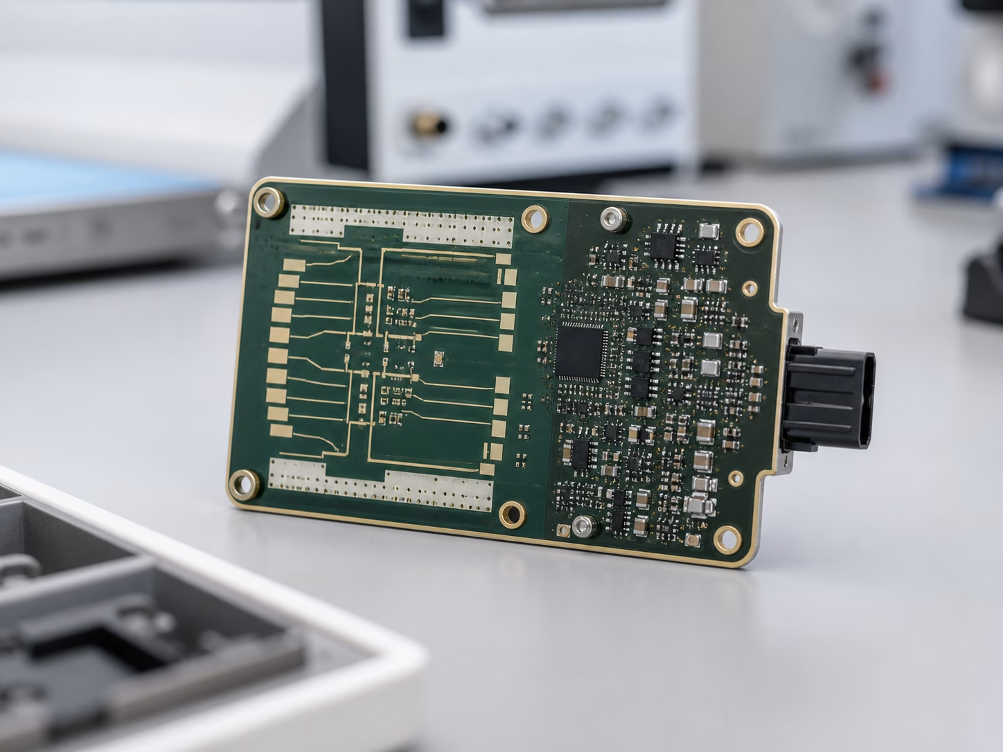
Our Rogers PCB Capabilities
Material Support for Rogers PCB Builds
Data Sheet Showing the Different Roger PCB Models (Table 1)
| Property | RO4350B | RO3003 | RO3006 | RO3010 | RO4835 | RO5880 | RO6002 | RO6010 | RO4003 | RO 4360G2 |
| Dk, Process | (2)3.48 ± 0.05 | 3.00 ± 0.04 | 6.15 ± 0.15 | 10.2 ± 0.30 | 3.48 ± 0.05 | 2.20 ± 0.02 | 2.94 ± 0.04 | 10.2 ± 0.25 | 3.38 ± 0.05 | 6.15 ± 0.15 |
| Dk Design | 3.66 | 3.00 | 6.50 | 11.20 | 3.66 | 2.20 | 2.94 | – | 3.55 | – |
|---|---|---|---|---|---|---|---|---|---|---|
| Dissipation Factor | 0.0037 0.0031 | 0.001 0 | 0.002 0 | 0.002 2 | 0.003 7 | 0.0004 0.0009 | 0.001 2 | 0.002 3 | 0.0027 0.0021 | 0.003 8 |
| Thermal Coefficient | +50 | -3 | -262 | -395 | +50 | -125 | +12 | -425 | +40 | – |
| Dimension Stability | – | -0.06 0.07 | -0.27 -0.15 | -0.35 -0.31 | – | – | – | – | – | – |
| Volume Resistivity | 1.2 X 10^10 | 10^7 | 10^5 | 10^5 | 5 x 10^8 | 2 x 10^7 | 10^6 | 5 x 10^5 | 1.7 X 10^10 | 4.0 x 10^13 |
| Surface Resistivity | 5.7 X 10^9 | 10^7 | 10^5 | 10^5 | 7 x 10^8 | 3 x 10^7 | 10^7 | 5 x 10^6 | 4.2 X 10^9 | 9.0 x 10^12 |
| Electrical Strength | 31.2 (780) | – | – | – | 30.2 (755) | 0.96 (0.23) | – | – | 31.2 (780) | 784 |
| Tensile Modulus | 16,767 (2,432) 14,153, (2,053) | 930 823 | 1498 1293 | 1902 1934 | 7780 (1128) | 1070 (156) 450 (65), 860 (125) 380 (55) | 828 (120) | 931 (135) | 19,650 (2,850) 19,450 (2,821) | – |
Table 2 (Continuation)
| Property | RO4350B | RO3003 | RO3006 | RO3010 | RO4835 | RO5880 | RO6002 | RO6010 | RO4003 | RO 4360G2 |
| Tensile Strength | 203 (29.5) 130 (18.9) | – | – | – | 136 (19.7) | – | – | 17 (2.4) | 139 (20.2) 100 (14.5) | 131 (19) 97 (14) |
|---|---|---|---|---|---|---|---|---|---|---|
| Flexural Strength | 255 (37) | – | – | – | 186 (27) | – | – | 4364 (633) | 276 (40) | 213 (31) 145 (21) |
| Dimensional Stability | <0.5 | – | – | – | <0.5 | – | – | – | <0.3 | – |
| Coefficient of Thermal Expansion | 10 12 32 | 17 16 25 | 17 17 24 | 13 11 16 | 10 12 32 | 31 48 237 | 16 16 24 | 24 24 24 | 11 14 46 | 13 14 28 |
| Tg | >280 | – | – | – | >280 | – | – | – | >280 | >280 |
| Td | 390 | 500 | 500 | 500 | 390 | 500 | 500 | 500 | 425 | 407 |
| Specific Heat | – | 0.9 | 0.86 | 0.8 | – | – | 0.93 (0.22) | 1.00 (0.239) | – | – |
| Thermal Conductivity | 0.69 | 0.50 | 0.79 | 0.95 | 0.66 | 0.22 | 0.60 | 0.78 | 0.71 | 0.75 |
| Moisture Absorption | 0.06 | 0.04 | 0.02 | 0.05 | 0.05 | 0.02 | 0.02 | 0.05 | 0.06 | 0.08 |
| Density | 1.86 | 2.1 | 2.6 | 2.8 | 1.92 | 2.2 | 2.1 | 3.1 | 1.79 | 2.16 |
| Copper Peel Strength | 0.88 (5.0) | 12.7 | 7.1 | 9.4 | 0.88 (5.0) | 31.2 (5.5) | 8.9 (1.6) | 12.3 (2.1) | 1.05 (6.0) | 5.2 (0.91) |
| Flammability | (3)V-0 | V-0 | V-0 | V-0 | V-0 | V-0 | V-0 | 94V-0 | N/A | V-0 |
| Lead-Free Process Compatible | Yes | Yes | Yes | Yes | Yes | Yes | Yes | Yes | Yes | – |
