PCBA Programming : A Step-by-Step Guide to Firmware Burning
Unlock the secrets of PCBA programming: This guide covers the complete process, methods, tools, and troubleshooting for writing firmware to your circuit boards.
Get Your PCB Quote!
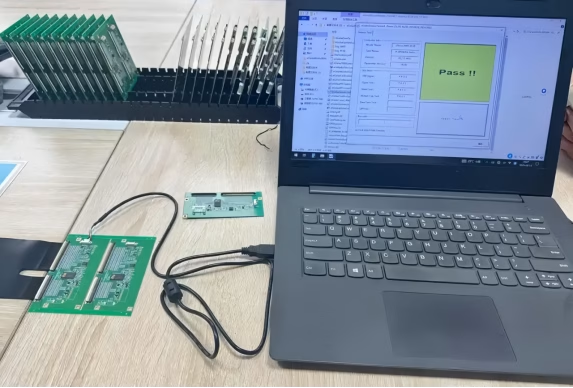
Table of Contents
- 1He aha te Papatonotanga PCBA (Tahu)?
- 2He aha te mea nui o te hōtaka PCBA mō ngā taputapu hiko?
- 3Te Tukanga Hōtaka PCBA Katoa: He Aratohu Hipanga-i-te-Hipanga
- 4Ngā Reo me ngā Utauta Hōtaka IC Noa
- 5Te Whakatau i ngā Wero o te Papatono PCBA
- 6Te Kōwhiri i te Otinga Papatono PCBA Tika
- 7. PCBA Phōtaka FAQs
- 8. Whakarapopototanga
Imagine a sophisticated electronic device—be it a smart home sensor, a medical gadget, or an industrial controller. What transforms a mere collection of components on a circuit board into a functional, intelligent machine? It’s the magic of PCBA Programming, often referred to as “burning” or “downloading” firmware. While Printed Circuit Board Assembly (PCBA) focuses on physically mounting and soldering components onto a bare printed circuit board (PCB), programming is the vital next step that injects intelligence, ensuring the device operates exactly as designed. Without this critical process, even the most perfectly assembled board remains a dormant shell. This guide will walk you through the comprehensive world of PCBA programming, from understanding its basics to mastering the process, methods, and essential troubleshooting techniques.
1. What is PCBA Programming (Burning)?
At its core, PCBA programming is the process of writing pre-compiled software, known as firmware, into the memory of an integrated circuit (IC) or microcontroller that is already mounted on a PCBA board. Think of a computer without an operating system; it has all the hardware but lacks instructions to perform tasks. Similarly, a PCBA without programmed ICs cannot function. This essential step imbues the electronic components with the specific instructions and logic required for their intended operation. It’s the critical link between hardware and software, bringing embedded systems to life. The terms “burning” or “downloading” are commonly used interchangeably with programming, referring to the act of permanently writing data to non-volatile memory on the chip.
2. Why is PCBA Programming Crucial for Electronics?
The importance of accurate and reliable PCBA programming cannot be overstated. It is the linchpin that ensures a product functions correctly, performs stably, and meets its design specifications. Without it, even a flawlessly manufactured PCB Assembly would be useless. This process allows for:
1) Functionality: Enabling the device to perform its intended tasks, from simple data processing to complex control algorithms.
2) Customization: Adapting a standard hardware platform for diverse applications by loading different firmware.
3) Performance & Stability: Ensuring that the device operates reliably and consistently under various conditions.
4) Debugging and Updates: Facilitating the correction of errors and the implementation of new features through firmware updates.
5) Mass Production Efficiency: Streamlining the manufacturing process by programming many boards quickly and consistently on a production line.
Ultimately, a precise programming process is what turns an assembled circuit board into a functional , high-performing electronic product, critical for everything from consumer electronics to advanced industrial equipment.
3. The Complete PCBA Programming Process: A Step-by-Step Guide
The journey from a blank IC to a fully functional programmed chip on a PCBA involves several meticulous steps. A reliable and precise programming process is paramount for product quality and performance. Here’s a breakdown of the complete workflow:
3.1 Preliminary Preparation
Before any code is “burned,” thorough preparation is essential. This involves:
1) Confirming the Firmware File: Verifying the correct firmware version and its checksum to ensure integrity and prevent loading erroneous code.
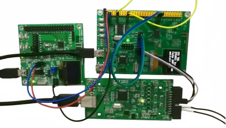
2) Checking Device Connection: Ensuring a stable and secure connection between the programmer tool (e.g., ST-Link, J-Link) and the target PCBA. This includes confirming the correct programming interface (e.g., JTAG, SWD, UART) is properly connected and free from looseness.
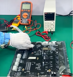
3) Power Supply Check: Confirming that the target board’s power supply (e.g., 3.3V/5V) is stable and within the IC’s operating range. Unstable voltage can lead to programming failures.
3.2 Programming Environment Setup
Setting up the right hardware and software environment is critical:
1) Programmer/Debugger: Selecting an appropriate programmer tool compatible with the target IC (e. g., in-circuit programmers, production programmers).
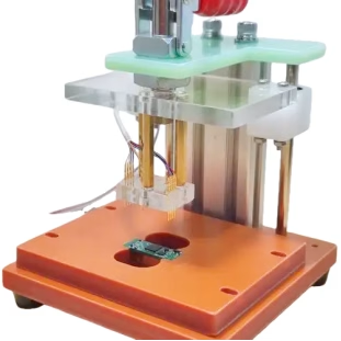
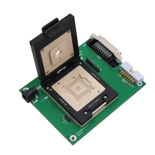
2) Programming Adapter/Jig: Often, a custom programming jig or fixture is used, especially for mass production. This ensures consistent contact with the PCBA’s programming interface.
3) Software Configuration: Installing and configuring the necessary programming software or integrated development environment (IDE) on a host computer. This includes drivers for the programmer tool.
3.3 Parameter Settings
Once the environment is ready, specific programming parameters must be configured within the software:
1) Chip Selection: Identifying the exact IC model being programmed.
2) Memory Address Ranges: Specifying the flash or EEPROM memory regions where the firmware will be written.
3) Programming Options: Selecting actions like “Erase,” “Write,” “Verify,” and potentially “Lock” (to prevent unauthorized reading).
4) Speed Settings: Adjusting the programming speed, which can impact programming time and success rate.
3.4 Burning Execution
With all preparations and settings complete, the programming process is initiated. The software sends the firmware data to the programmer, which then translates it into electrical signals to write the code onto the target IC’s memory. During this phase, it’s common to monitor progress indicators and watch for any error messages.
3.5 Functional Verification and Testing
After programming, verifying the integrity and functionality of the burned firmware is crucial. This step ensures that the code was written correctly and that the device operates as intended. Various testing methods are employed:
| Test Method | Description | Purpose |
| In-Circuit Test (ICT) | Automated test using a “bed-of -nails” fixture to check for shorts, opens, resistance, capacitance, and basic IC functionality. | Detects manufacturing defects and verifies component values and connections. |
| Flying Probe Testing (FPT) | Robotic probes move across the PCBA to contact test points, checking for opens, shorts, and component presence. | Flexible for prototyping and low-volume production; eliminates need for expensive test jigs. |
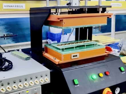
| Bed-of-Nails Testing | A test jig with spring-loaded pins makes contact with multiple test nodes on the PCBA. | Provides comprehensive, high-speed testing for high-volume production. |
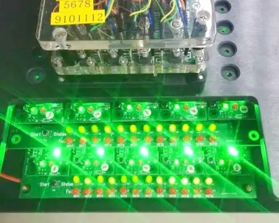
| Functional Test (FT) | Simulates the actual operating environment of the device, verifying its full functionality. | Confirms the device performs its intended purpose post-programming. |
These tests confirm the successful programming and initial operational state of the embedded systems.
3.6 Record Keeping
For traceability and quality control, documenting each programming session is vital. This includes logging:
- The firmware version programmed.
- The unique serial number of the PCBA (if applicable).
- The date and time of programming.
- The result (pass/fail) and any encountered errors.
This data is invaluable for future troubleshooting, recalls, or performance analysis on the production line.
4. Common IC Programming Languages and Tools
The choice of programming language and tools depends heavily on the type of IC and its application. Understanding these is key for successful IC programming.
4.1 Programming Languages
1) C/C++: These are the dominant languages for microcontroller programming. They offer a good balance of low-level hardware control and high-level abstraction, making them suitable for most embedded applications, from simple sensors to complex control systems.
2) Verilog/VHDL: These Hardware Description Languages (HDLs) are used for programming Field-Programmable Gate Arrays (FPGAs) and Application-Specific Integrated Circuits (ASICs). They describe the digital logic and hardware architecture rather than sequential software instructions.
3) Assembly Language: While less common for direct application programming today, assembly is occasionally used for highly performance-critical routines or specific low-level hardware interactions where C/C++ might introduce too much overhead.
4.2 Programming Tools
The tools landscape is diverse, ranging from simple USB programmers for hobbyists to sophisticated automated systems for manufacturers:
1) Dedicated Programmers: Devices like J-Link, ST-Link, or proprietary tools from chip manufacturers (e.g., Micro chip’s PICkit) connect to the PCBA and manage the actual data transfer.
2) Development Boards: Many development boards (like Arduino or Raspberry Pi) come with integrated debuggers and programmers, simplifying the initial programming for prototypes.
3) Integrated Development Environments (IDEs): Software suites like Keil MDK, IAR Embedded Workbench, or VS Code with relevant extensions provide a comprehensive environment for writing, compiling, and debugging code , often integrating with programming tools.
4) Automated Test Equipment (ATE): For high-volume manufacturing, fully automated systems can handle programming, testing, and even packaging, minimizing human intervention and maximizing throughput.
5. Troubleshooting PCBA Programming Challenges
Even with meticulous preparation, issues can arise during firmware burning. Knowing how to diagnose and resolve common problems is crucial for efficient development and production.
1) Programming Failure/Verification Error: This is a common issue.
- Cause:Incorrect firmware file, poor connection, unstable power supply, incorrect programming parameters, or faulty IC.
- Solution:Double-check file integrity (checksum), ensure all cables are secure, verify power supply stability, confirm correct chip selection and memory settings, try a different IC if possible.
2) Device Not Recognized: The programming tool cannot detect the target IC.
- Cause:Incorrect programming interface (JTAG, SWD, UART) selected, driver issues, faulty programmer, or incorrect wiring on the PCBA.
- Solution:Verify interface selection, reinstall programmer drivers, check continuity of programming lines on the PCBA, try a known-good programmer.
3) Slow Programming Speed: The burning process takes an unusually long time.
- Cause:Suboptimal programming speed settings, high communication latency, or large firmware size with slow memory write times.
- Solution:Adjust programming speed settings in the software, ensure direct connection to the PC, optimize firmware size where possible.
4) Intermittent Errors : Programming sometimes succeeds, sometimes fails.
- Cause:Unstable power supply, noisy environment, loose connections, or thermal issues.
- Solution:Ensure a clean power source, minimize electromagnetic interference, inspect all connections for looseness, check IC temperature during programming.
5) Post-Programming Functionality Issues: The device programs successfully but doesn’t work as expected.
- Cause:Logic errors in the firmware, incorrect fuse bits or configuration settings programmed, or underlying hardware defects not caught by programming verification.
- Solution:Utilize debugging tools to step through code, re-check fuse bit settings, perform detailed functional tests to isolate hardware vs. software issues.
6. Choosing the Right PCBA Programming Solution
Selecting the appropriate programming strategy is vital for both prototyping and mass production. Factors to consider include project complexity, production volume, budget, and desired level of automation.
1) In-House Programming: Suitable for low -volume production, R&D, and projects requiring high levels of control over the programming process. Requires investment in programming tools, fixtures, and skilled personnel.
2) Outsourcing to PCBA Service Providers: Many PCBA manufacturers offer integrated IC programming services as part of their PCB Assembly offerings. This is often the most cost-effective and efficient solution for medium to high-volume production.
- Benefits:Reduces internal capital expenditure, leverages manufacturer expertise, ensures consistent quality, and integrates seamlessly into the overall assembly and testing workflow.
- Considerations:Clear communication of firmware versions, programming parameters, and testing requirements is crucial.
3) Automated Programming Systems: For very high-volume production, automated systems can handle multiple boards simultaneously, performing programming, verification, and even basic functional tests with minimal human intervention.
The key is to partner with a reliable provider or establish an in-house process that prioritizes accuracy, speed, and consistent quality, aligning with the project’s specific demands.
7. PCBA Programming FAQs
PCB assembly (PCBA) is the physical process of mounting and soldering electronic components onto a bare printed circuit board. PCBA programming, on the other hand, is the process of writing software (firmware) into the memory of the integrated circuits (ICs) that have been assembled onto the board, giving the board its functional intelligence.
Yes, some ICs can be programmed “offline” before being mounted, a process known as pre-programming or “pre-burning.” This is often done for high-volume parts or when in-circuit programming is difficult. However, in-circuit programming (on the assembled PCBA) offers the advantage of verifying the entire circuit’s functionality after programming.
JTAG (Joint Test Action Group) and SWD (Serial Wire Debug) are common debugging and programming interfaces used for microcontrollers and other complex ICs. They provide a standardized way to communicate with the chip’s internal logic, allowing for firmware burning, real-time debugging, and boundary-scan testing. They are critical for both development and production programming.
If PCBA programming fails, the IC will likely not contain the correct firmware, preventing the device from functioning as intended. This can lead to device malfunction, incorrect operation, or the device remaining completely unresponsive. Troubleshooting steps, as outlined in this guide, are then required to identify and fix the issue.
8. Summary
PCBA programming is an indispensable stage in the lifecycle of any electronic product, transforming a collection of components into a smart, functional device. From the initial preparation and parameter settings to the actual burning execution and rigorous functional verification, each step demands precision and expertise. Understanding the various programming interfaces like JTAG, SWD, and UART, along with common languages like C/C++, is key to success. By employing robust testing methods such as ICT, Flying Probe Testing, and Bed-of-Nails Testing, and proactively addressing troubleshooting challenges , manufacturers can ensure flawless firmware integration and superior product performance. Whether handled in-house or outsourced to specialized PCBA service providers, mastering this process is paramount for reliable electronics on the production line.

Get Quote Free