Aluminum PCB Guide: Enhanced Thermal Management
This guide explains how aluminum core PCBs work, when they earn their extra cost, and what to put in a fabrication request so the quoted board matches the thermal problem you are trying to solve.
Get Your PCB Quote!
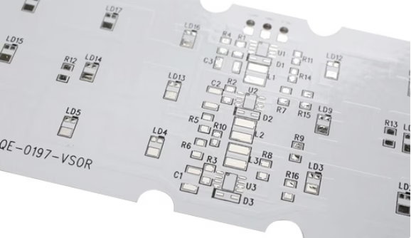
Table of Contents
When a power device runs hot, changing the PCB material can be more effective than adding another heatsink after the layout is finished. An aluminum PCB gives heat a controlled path from the copper circuit, through a thermally conductive dielectric, and into a metal base that can spread it into a chassis or external heatsink.
That does not mean aluminum is automatically the right choice. The dielectric layer, mounting interface, copper weight, component placement, and airflow determine the final thermal result. A poorly specified aluminum board can still create a hot spot; a well-designed FR-4 board may be the better choice for a low-power control circuit.
Quick specifications
| Design question | Practical starting point |
| Primary reason to choose aluminum | Heat spreading from LEDs, power semiconductors, or converters |
| Typical construction | Copper circuit layer, electrically insulating thermal dielectric, aluminum base |
| Most common format | Single-sided metal-core PCB |
| Key thermal variable | Dielectric thermal resistance and thickness, not the aluminum base alone |
| Common applications | LED lighting, motor control, power supplies, automotive electronics, industrial equipment |
| Main trade-off | Better thermal path, but less routing flexibility and more process constraints than FR-4 |
| Design references | IPC-2221C for generic board design; IPC-2152 for current-carrying conductors |
Key takeaways
- An aluminum core does not replace a heatsink. It lowers the thermal resistance between the component and the board’s mounting surface, which must still be designed to remove heat.
- The dielectric is the thermal bottleneck in a metal-core PCB. Ask for its thermal conductivity, thickness, dielectric strength, and test method instead of comparing aluminum alloy names alone.
- Single-sided aluminum PCBs are the straightforward option for LED and power layouts. Multilayer and hybrid constructions are possible, but they require early agreement on vias, insulation, lamination, and routing.
- Do not size power traces from copper weight alone. Use current, allowable temperature rise, conductor geometry, ambient conditions, and the board stackup together. IPC-2152 is a useful design reference for that calculation.
- Send the manufacturer the thermal target and mounting details with the Gerbers. A DFM review cannot validate a thermal design if the intended heatsink, interface material, or operating conditions are missing.
- Treat every published thermal-conductivity number as a material-test result, not a guaranteed board temperature. The finished thermal path still needs a calculation or measurement.
What is an aluminum PCB?
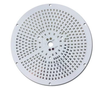
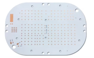
An aluminum PCB, also called an aluminum core PCB, metal-core PCB (MCPCB), or aluminum-backed PCB, uses aluminum as a structural and heat-spreading base beneath the circuit layer. The aluminum is conductive, so it cannot touch the copper circuit directly. An electrically insulating dielectric separates the two while allowing heat to pass through.
A conventional FR-4 board primarily uses glass-reinforced epoxy laminate as its structural and insulating material. FR-4 can carry heat laterally through copper planes and into components or a chassis, but its dielectric path is not intended to act as a dedicated thermal interface. That difference matters when a component’s junction temperature is limited and the heat source sits close to the board surface.
The useful question is not “Does aluminum conduct heat?” It is “What is the complete thermal path from the component junction to the final heat sink?” That path can include:
- The component package and exposed pad
- Solder and copper land
- Copper circuit layer
- Thermal dielectric
- Aluminum base
- Thermal interface material, screws, clips, or a bonded heatsink
- Chassis or surrounding air
Every interface adds thermal resistance. If the board is mounted with an air gap, an undersized interface pad, or a poorly flat heatsink, the aluminum base cannot deliver the expected improvement.
For a broader view of custom constructions, see PCBAndAssembly’s aluminum PCB service and its metal core PCB service.
Aluminum PCB stackup and heat flow
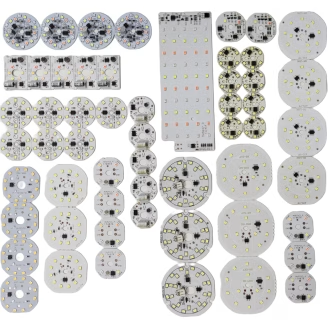
Most aluminum PCBs used for lighting and power conversion use a simple three-part stackup.
1. Copper circuit layer
The copper foil is etched into traces, pads, planes, and thermal lands. Its thickness affects current capacity, copper loss, spreading resistance, and manufacturability. A heavier copper layer can help with current and lateral heat spreading, but it also changes etching, spacing, pad geometry, and soldering requirements.
Do not specify “2 oz copper” as a substitute for a current and temperature-rise requirement. State the continuous and peak current, the allowable conductor temperature rise, and whether the trace is internal or exposed. The current-carrying guidance in IPC-2152 treats conductor size, copper thickness, board material, and temperature rise as connected variables.
2. Thermal dielectric layer
The dielectric provides the electrical isolation between copper and aluminum. It is also the main thermal bottleneck in many aluminum PCBs.
When comparing material options, request these values:
- Thermal conductivity, with units and test method
- Dielectric breakdown strength
- Dielectric thickness and tolerance
- Maximum operating temperature
- Coefficient of thermal expansion (CTE)
- Peel strength or bond reliability, where relevant
Higher thermal conductivity is useful, but a thinner dielectric with lower breakdown strength may not be acceptable for a high-voltage design. The best choice balances thermal resistance, electrical clearance, voltage stress, production yield, and cost.
3. Aluminum base
The aluminum base provides stiffness and spreads heat away from the hot area. Common alloy choices are a supplier and application decision, not a universal ranking. A high-conductivity alloy may be attractive for a stationary lighting board; a stronger alloy or a different thickness may be more suitable when the board is part of a mechanically loaded assembly.
Specify the base thickness, flatness requirement, exposed or coated surfaces, mounting-hole treatment, and corrosion or finish requirements. If the aluminum will contact a chassis, include the contact area and fastener pattern in the mechanical drawing.
Engineering note
A board can have a high-conductivity aluminum base and still perform poorly if the dielectric is thick, the thermal pad is undersized, or the mounting interface is uneven. Thermal design should compare the resistance of the entire path, not a single material datasheet.
For a simple through-plane section, the dielectric contribution can be estimated with:
Rθ = t / (k × A)
where t is dielectric thickness in meters, k is thermal conductivity in W/m·K, and A is the effective heat-transfer area in square meters. Consider an illustrative, not production-guaranteed, case: a 0.10mm dielectric rated at 2.0 W/m·K under a 20mm × 20mm thermal land gives Rθ = 0.00010 / (2.0 × 0.0004) = 0.125 K/W through that idealized section. At 4W, that portion would represent about 0.5°C of temperature rise.
The result is deliberately optimistic. It does not include spreading resistance, solder, copper constriction, surface roughness, interface pressure, or the heatsink-to-ambient path. The practical value of the calculation is that it shows why “aluminum is highly conductive” is not enough information to approve a design.
The equation follows the standard thermal-resistance relationship described in ROHM’s thermal design application note. The numeric example above is an engineering estimate using stated assumptions, not a supplier test result.
What generic aluminum PCB guides often get wrong
Many articles compare the thermal conductivity of aluminum with the nominal through-plane conductivity of FR-4 and then predict a fixed temperature or lifetime improvement. That shortcut is unsafe. FR-4 performance depends on copper area, planes, vias, airflow, and the enclosure; aluminum PCB performance depends on the dielectric and mounting interface as much as the base metal.
The same problem appears in claims that an aluminum PCB will dissipate heat “eight to nine times faster” than FR-4. Without the test board, copper pattern, heat load, boundary conditions, and measurement method, that number is not transferable to a customer’s design. A defensible specification states the allowed temperature rise and validates it on the finished assembly.
What generic aluminum PCB guides often get wrong
Many articles compare the thermal conductivity of aluminum with the nominal through-plane conductivity of FR-4 and then predict a fixed temperature or lifetime improvement. That shortcut is unsafe. FR-4 performance depends on copper area, planes, vias, airflow, and the enclosure; aluminum PCB performance depends on the dielectric and mounting interface as much as the base metal.
The same problem appears in claims that an aluminum PCB will dissipate heat “eight to nine times faster” than FR-4. Without the test board, copper pattern, heat load, boundary conditions, and measurement method, that number is not transferable to a customer’s design. A defensible specification states the allowed temperature rise and validates it on the finished assembly.
When should you choose an aluminum core PCB?
Use this decision path before changing the material in your CAD library.
Choose aluminum when these conditions line up
- A component or group of components creates a concentrated heat source.
- The board can expose one side to a chassis, heatsink, or controlled mounting surface.
- The design benefits from a rigid, flat thermal spreader.
- The required routing can fit a single-sided or limited-layer construction.
- The extra fabrication and assembly constraints are acceptable for the volume and budget.
Stay with FR-4 when these conditions dominate
- The board is low power and thermal rise is already within the component rating.
- Dense routing, plated through-holes, or conventional multilayer connectivity is the main challenge.
- The product needs flexing or a complex rigid-flex shape.
- The enclosure has no meaningful thermal path from the board to the outside environment.
- A dedicated heatsink or cold plate solves the thermal issue more efficiently at system level.
The right comparison is not “aluminum is better than FR-4.” It is “which stackup solves the dominant constraint at acceptable cost?” Use FR-4 PCB fabrication as the baseline when heat is not the limiting factor.
Aluminum PCB versus FR-4
| Factor | Aluminum PCB | FR-4 PCB |
| Thermal path | Dedicated metal base and thermal dielectric | Mainly through copper, laminate, and external thermal hardware |
| Routing flexibility | Best for simple or limited-layer layouts | Broad multilayer and via options |
| Mechanical behavior | Rigid metal-backed structure | Lightweight glass-reinforced laminate |
| Typical strength | LED modules and concentrated power loads | General electronics and dense digital designs |
| Cost driver | Thermal dielectric, base preparation, and custom construction | Layer count, material grade, copper, and fabrication tolerances |
| Main design risk | Electrical isolation, drilling, and mounting interface | Local hot spots and insufficient copper or heatsinking |
For high-current designs where thermal management and current capacity are both limiting factors, evaluate aluminum alongside a heavy copper PCB, not as an alternative to it. The two approaches solve different parts of the problem and can sometimes be combined.
Aluminum PCB types and suitable applications
Single-sided aluminum PCB
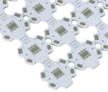
The standard construction places one copper circuit layer over the dielectric and aluminum base. It is usually the simplest and most economical metal-core format. Typical uses include LED boards, power resistors, DC/DC converter modules, and compact motor-control sections.
Double-sided or hybrid aluminum PCB
Hybrid constructions combine a metal-backed section with FR-4 circuitry or another insulated layer. They can add routing capacity while keeping aluminum under the highest heat sources. The boundary between materials needs careful review because the stackup affects thickness, CTE behavior, drilling, soldering, and component placement.
Multilayer metal-core PCB
Multilayer aluminum designs can support more complex circuits, but the aluminum core changes how the board is drilled, insulated, laminated, and interconnected. A through-hole that would be routine on FR-4 may require a different pad, insulation, or process sequence. Define the layer count and via strategy with the manufacturer before routing is locked.
IPC-2222 identifies multilayer metal-core boards as distinct board types: Type 5 without blind or buried vias, and Type 6 with them. The current IPC-2222B listing confirms the active revision, while the openly available IPC preview shows the metal-core classifications. Neither is a substitute for purchasing the standard when you need contractual requirements. Check the current revision status in the IPC document revision table, rather than copying an old design note.
Flexible or bendable thermal constructions
Some products use thin metal foils or hybrid flex constructions for limited forming. These are not drop-in replacements for standard rigid aluminum PCBs. Ask for the allowed bend radius, bend-cycle target, neutral-axis design, and thermal-cycle data. If the board must flex repeatedly, a conventional aluminum core may be the wrong starting point.
Application fit
| Application | Why aluminum can help | Design question to answer first |
| LED lighting | Spreads heat from high-power LED packages | Will the base contact a heatsink or luminaire body? |
| Power supplies and converters | Reduces the thermal path from switching devices | What are the continuous and peak losses? |
| Automotive lighting | Combines rigidity with a compact heat path | What vibration, temperature, and mounting requirements apply? |
| Motor drives | Supports localized power-device cooling | Does the board need multilayer control routing? |
| Industrial equipment | Helps maintain temperature margin in a rigid module | What enclosure and airflow conditions are guaranteed? |
| Medical or laboratory equipment | Can support stable thermal behavior in lighting and power sections | What validation, traceability, and acceptance class are required? |
Aluminum PCB design and manufacturing checklist
Place heat sources deliberately
Start with the thermal map, not the outline. Group heat-generating components over the aluminum area that can connect to the final heat sink. Keep temperature-sensitive parts away from the hot zone, and leave enough copper around exposed pads to spread heat without creating solder imbalance.
If several power devices share a base, model their combined load. A board that passes a single-device bench test may fail when adjacent devices heat the same aluminum region. Include worst-case ambient temperature, duty cycle, enclosure conditions, and tolerances in the calculation.
Define the thermal interface
Tell the fabricator how the board will be mounted. Include:
- Heatsink or chassis material and flatness
- Thermal interface material type and target thickness
- Fastener locations and torque limits
- Required exposed aluminum areas
- Electrical isolation requirements at mounting holes
- Whether the board surface will be anodized, coated, or left bare
This information affects both board fabrication and final assembly. If you only send Gerbers, the manufacturer can check geometry but cannot confirm whether the intended thermal interface is realistic.
Review isolation and clearances
The aluminum base is conductive. Copper pads, vias, mounting holes, and exposed metal must be isolated according to the voltage and safety requirements of the product. Do not assume that a solder mask layer is the only protection needed.
For a high-voltage design, define the required dielectric system and voltage test method. For a chassis-mounted board, identify which holes need insulated bushings or nonconductive hardware. These choices should be part of the drawing and DFM review, not a production-floor guess.
Plan drilling, routing, and panelization
Metal-backed boards do not behave exactly like FR-4 during routing and drilling. Confirm the manufacturer’s minimum hole, edge, slot, and copper-to-edge rules for the selected base thickness. Also review panelization: the aluminum frame can affect tooling, depanelization force, and scrap utilization.
For an assembled board, make sure component placement leaves access for soldering, inspection, and mounting. A thermally efficient layout that cannot be inspected around large power packages is not production-ready.
Check the failure modes before release
Ask the supplier to review these failure modes specifically:
- A thermal land is large enough for heat spreading but too large or too uneven for a stable solder joint.
- A mounting hole or exposed aluminum area creates an unintended electrical path to the chassis.
- The thermal target assumes a heatsink contact area that the enclosure does not actually provide.
- A copper-weight change alters etching, clearances, or solder volume after the thermal design is approved.
- Several devices share one base area, so the hot spots interact even though each device passes an isolated calculation.
PCBAndAssembly can provide DFM/DFA feedback, but customer-specific thermal test data, field failure rates, and project measurements should only be published when they are documented and approved for disclosure. This article therefore separates our manufacturing recommendations from third-party standards and vendor-reported material data.
Specify assembly and inspection
Aluminum-backed boards can support surface-mount components, but the assembly profile must match the selected materials and component package. Define the acceptance class and inspection plan. Depending on the design, that may include solder paste inspection, Automated Optical Inspection (AOI), electrical testing, and functional testing.
When fabrication and assembly come from different suppliers, each handoff creates an opportunity for the thermal and mechanical requirements to be lost. A one-stop supplier can review the bare board, component placement, soldering, and final test as one process. Request a PCB fabrication and assembly quote with the thermal requirements attached to the design package.
How to read thermal data honestly
Use the following confidence labels when you review a quote or design report:
- Verified standard or method:IPC-2221C is the current generic printed-board design revision listed by IPC. IPC-2152 defines a current-carrying design approach, but IPC lists it as no longer maintained, so treat it as a reference and confirm the method with your design authority.
- Vendor-reported data:A thermal-material supplier may publish conductivity, thermal impedance, pressure, and test-method values for a specific product. Those values are useful for comparison, but they are not a measurement of your finished aluminum PCB.
- Engineering estimate:A calculation such as Rθ = t / (k × A) is only as reliable as its assumptions. Label it as an estimate and validate it with a prototype or production test.
This distinction matters because two suppliers can quote the same nominal conductivity while using different test methods, thicknesses, and effective areas. Compare like with like before making a material decision.
Sources and further reading
The sources below are included so a reader can reproduce the main technical reasoning. They do not all carry the same level of authority:
- IPC-2221C revision status, primary standards-body reference for the current generic board-design revision.
- IPC-2222A preview, primary IPC preview that identifies multilayer metal-core board types. Use the purchased current revision for contractual requirements.
- IPC-2222B listing, current revision listing from the Global Electronics Association standards store.
- IPC-2152, IPC current-carrying design reference. IPC’s revision table marks it as no longer maintained, so it should not be presented as a current revision standard without qualification.
- ROHM thermal design application note, component-manufacturer application guidance for the thermal-resistance relationship used in the worked example.
- Henkel BERGQUIST SIL PAD TSP K900 data, vendor-reported thermal impedance and dielectric-strength data for one thermal-interface product; it is an example of how to read a datasheet, not a universal aluminum-PCB specification.
Aluminum PCB FAQ
Are aluminum PCBs better than FR-4?
They are better for many boards with concentrated heat and a usable path to a heatsink or chassis. FR-4 remains the practical choice for many low-power and densely routed designs. Compare the complete thermal and electrical requirements instead of choosing by material name.
Can an aluminum PCB have multiple layers?
Yes. Multilayer metal-core and hybrid constructions are available, but they need a stackup and via plan agreed with the fabricator early. The aluminum changes isolation, drilling, lamination, and interconnection rules compared with a standard multilayer FR-4 board.
Can aluminum PCBs use SMT components?
Yes. Aluminum PCBs commonly carry surface-mount LEDs, power devices, resistors, and control components. The land pattern, solder profile, copper balance, and inspection plan still need to match the assembly process.
Does aluminum PCB mean the board needs no heatsink?
No. The aluminum base spreads heat, but it must transfer that heat somewhere. If the board is trapped inside a sealed enclosure with no thermal path, the benefit may be limited. Specify the board-to-chassis or board-to-heatsink interface as part of the thermal design.
Is an aluminum PCB more expensive than FR-4?
Often, especially for simple single-sided boards, because the thermal dielectric, metal base preparation, and special processing add cost. The total product cost can still be lower if the board eliminates a separate heatsink, reduces assembly steps, or improves thermal reliability. Ask for a comparison based on the same quantity and thermal target.
How do I calculate aluminum PCB trace width?
Use the required current, copper thickness, conductor geometry, allowable temperature rise, and surrounding construction. IPC-2152 provides a reference method for current-carrying capacity; a manufacturer should review the finished geometry and operating conditions before production release.
What files should I send for an aluminum PCB quote?
Send Gerber or ODB++ files, drill data, a fabrication drawing, stackup or material requirements, copper weights, controlled dimensions, and the assembly files if components will be placed. Add the power-loss estimate, ambient range, thermal interface drawing, and required tests. Those details produce a more useful quote than a bare board outline alone.
Conclusion
An aluminum PCB is a thermal design tool, not simply a stronger version of FR-4. Its value comes from creating a predictable path from hot components to a real heat-spreading and heat-rejection surface. The dielectric specification, copper geometry, mounting interface, isolation rules, and assembly process determine whether that path works.
Choose aluminum when concentrated heat is the main constraint and the product can use the metal base effectively. Choose FR-4 when routing density, multilayer connectivity, flexibility, or low cost matters more than board-level heat spreading. For either material, give the manufacturer the operating conditions and thermal target before the design is finalized.
If you are ready to compare materials or validate a production stackup, send your PCB files to PCBAndAssembly for a quote and DFM review.

Get Quote Free