How to Solder Castellated Holes in PCB Design?
The guide delves into castellated mounting holes, exploring their design principles, advantages, manufacturing complexities and best practices for soldering.
Get Your PCB Quote!

Table of Contents
- 1. Quid are Castellatum adscendens Foramina?
- 2Commoda Castellatorum Mounting foramina
- 3Considerationes Designandi pro Castellatis Mounting foramina
- 4. Difficultates Fabricationis Foraminum Castellatorum
- 5Quomodo Foramina Castellata Soldare?
- 6Applicationes Claves of Mo castellataunting foramina
- 7. Mo castellataunting foramina FAQs
- 8. summary
- Key Takeaways
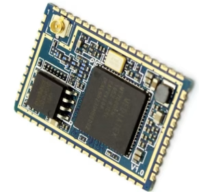
In the intricate world of Printed Circuit Board(PCB) design and manufacturing, every detail, no matter how small, plays a crucial role in functionality, reliability, and cost-effectiveness. Among the many specialized features, castellated mounting holes have emerged as a vital element, particularly for creating compact, modular electronic systems. These unique half-holes, typically found along the edge of a PCB, allow for direct soldering of one board onto another, facilitating the integration of modules and sub-assemblies.
This comprehensive guide delves into the specifics of castellated mounting holes, exploring their design principles, myriad advantages, manufacturing complexities, and best practices for soldering. Understanding these aspects is essential for engineers and designers aiming to leverage the full potential of modular electronics and optimize their PCB design for performance and efficiency.
1. What are Castellated Mounting Holes?
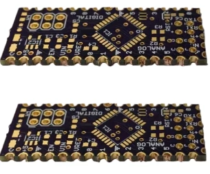
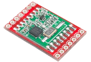
Castellated mounting holes, sometimes referred to as “castellations”, are essentially plated through-holes that are cut in half along the edge of a PCB. The term “castellated” derives from their resemblance to the battlements of a castle wall. These holes are typically plated with copper and often finished with solder, creating a reliable, solderable contact point along the board’s periphery.
Unlike standard through-holes that are fully enclosed within the PCB, castellated mounting holes expose half of their plated barrel to the outside edge. This design facilitates surface-mount assembly processes, allowing a module with castellated edges to be mounted directly onto a larger baseboard. Each castellation acts as an electrical and mechanical connection point, forming a robust link between the module and the host PCB. This approach significantly simplifies integration, making modules appear almost like large surface-mount components.
2. Advantages of Castellated Mounting Holes
The strategic use of castellated mounting holes offers a multitude of benefits, driving their increasing adoption across various industries:
- Modular Design Facilitation:Castellated holes are ideal for creating self-contained, pre-tested modules(e.g., Wi-Fi modules, Bluetooth modules, microcontrollers). These modules can then be easily soldered onto a larger carrier board, accelerating product development and simplifying assembly.
- Space Saving and Miniaturization:By allowing modules to sit flush against the carrier board without connectors, castellated holes contribute to more compact designs, crucial for miniaturized devices like wearables, IoT sensors, and mobile electronics.
- Enhanced Reliability: Soldered connections offer superior mechanical strength and electrical integrity compared to many types of connectors, leading to more robust and reliable products, especially in high-vibration or harsh environments.
- Simplified Rework and Replacement:In some cases, a module with castellated mounting holes can be easily removed and replaced if a defect occurs or an upgrade is needed, though this requires careful desoldering techniques.
- Cost Reduction:Eliminating expensive connectors can lead to significant cost savings in mass production. Furthermore, the ability to test modules independently before final assembly reduces overall testing complexity and potential rework costs at the system level.
- Design Flexibility:They provide greater flexibility in routing and placement, as the module can often be positioned closer to other components.
- As Test Points:Castellations can also serve as convenient test points during development and debugging, allowing easy access to signals.
These advantages of castellated holes make them a preferred choice for complex electronic assemblies where space, reliability, and modularity are paramount.
3. Design Considerations for Castellated Mounting Holes
Effective integration of castellated holes begins with meticulous PCB design. Several critical parameters must be carefully considered to ensure successful manufacturing and reliable performance:
| Design Parameter | Recommendation/Consideration | Impact |
| Drill Diameter | Typically 0.6mm to 1.2mm(24 to 48 mil). Must allow for robust plating. | Too small: manufacturing difficulty; Too large: weakens board edge. |
| Pad Size | Circular pad extending beyond the half-hole on the board surface. Sufficient area for solder fillet. | In adequate pad leads to poor solder joint strength and inspectability. |
| Copper Annular Ring | Ensure sufficient copper around the drilled hole prior to routing. Important for plating integrity. | Insufficient ring can cause delamination during milling or poor electrical connection. |
| Plating Thickness | Standard PCB plating thickness (e.g., 20-25 microns/0.8-1 mil) is usually sufficient, but may be specified higher for robust connections. | Ensures good electrical conductivity and solderability. |
| Solder Mask Clearance | Define solder mask opening larger than the pad to expose the entire castellated surface. | Proper solder mask clearance is critical for solder wetting and fillet formation. |
| Panelization Strategy | Must be designed as part of a panel with breakaway tabs, allowing the final routing to cut through the plated holes. | Incorrect panelization makes manufacturing impossible or overly complex. |
| Edge Clearance | Ensure no critical traces or components are too close to the edge where the castellations are formed. | Prevents damage to internal circuitry during the edge routing process. |
It’s crucial to communicate these design specifications clearly with your PCB manufacturer, as different fabs may have slightly varying capabilities and tolerances for castellated mounting holes.
4. Castellated Hole Manufacturing Challenges
While highly beneficial, the production of castellated holes introduces unique challenges for PCB manufacturers. These specialized features require precision and specific processes that go beyond standard PCB fabrication:
- Precision Drilling and Plating:The initial through-holes must be drilled with high accuracy and subsequently plated to ensure a consistent copper barrel. Any imperfections in plating can lead to poor conductivity or delamination once the holes are cut.
- Edge Routing/Milling Accuracy:This is the most critical step. After drilling and plating, the PCB edges are precisely routed or milled to cut through the centers of the plated holes. This process requires extremely tight tolerances to ensure that each castellation is a perfect half-cylinder with exposed plating. Inaccurate milling can result in uneven half-holes, burrs, or damage to the plating.
- Burr Formation:The routing process can sometimes leave burrs or rough edges on the castellations, which can impede soldering and affect aesthetics. Manufacturers must employ techniques to minimize burr formation and ensure smooth edges.
- Tool Wear:Cutting through plated copper and fiberglass composite material causes significant wear on routing bits, necessitating frequent tool changes and precise machine calibration. This impacts manufacturing cost and time.
- Quality Control and Inspection:Inspect ing castellated holes requires specialized vision systems to verify plating integrity, hole geometry, and absence of defects. Manual inspection can be challenging due to the small size and edge location.
- Cost Implications:Due to the additional precision required in drilling, plating, and especially the final routing step, PCBs with castellated holes often have a higher manufacturing cost per board compared to standard PCBs.
Addressing these castellated mounting hole manufacturing challenges necessitates experienced fabricators and advanced equipment to achieve high-quality results.
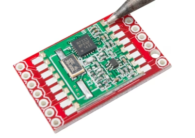
5. How to Solder Castellated Holes?
Proper soldering is vital for creating reliable electrical and mechanical connections using castellated holes. Both automated reflow and manual soldering techniques can be employed, each with its considerations:
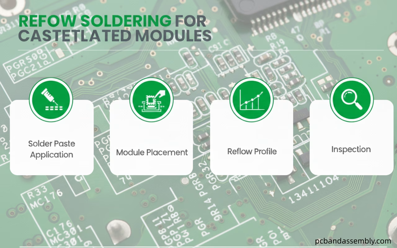
5.1 Reflow Soldering for Castellated Modules
This is the most common method for mass production of modules with castellated holes onto a host board:
- Solder Paste Application:Solder paste is applied to the pads on the host PCB using a stencil. The stencil aperture design for castellated pads is critical; it often needs to be slightly larger than the pad itself or specifically shaped to ensure sufficient paste volume is deposited to form a robust fillet around the castellation.
- Module Placement:The module with castellated holes is accurately placed onto the solder paste deposits on the host board, ensuring proper alignment of the castellations with their corresponding pads.
- Reflow Profile:A standard reflow soldering profile appropriate for the solder paste and components used is typically followed. During reflow, the solder paste melts, wets the castellated hole, and forms a strong fillet, connecting the module to the host board.
- Inspection:Post-reflow inspection(AOI or X-ray) is crucial to verify proper solder fillet formation, absence of bridges, and good wetting on all castellations.
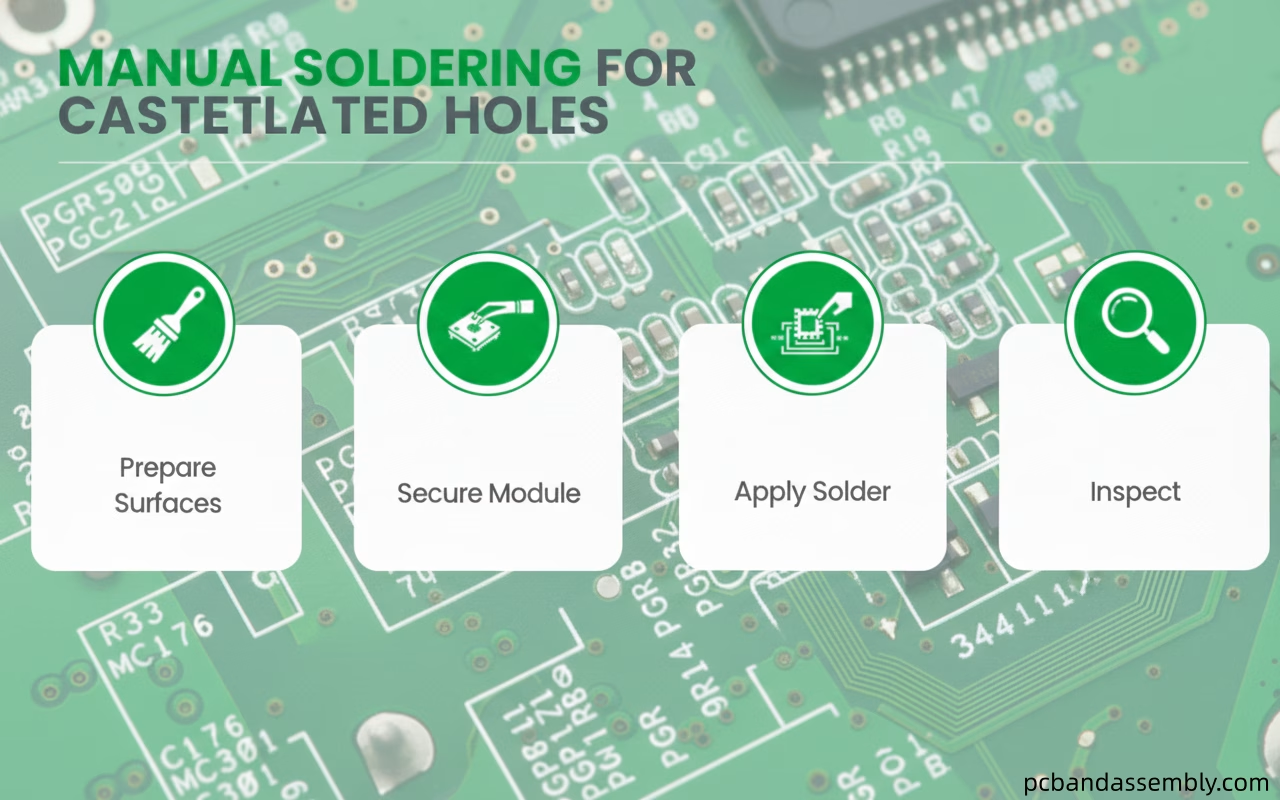
5.2 Manual Soldering for Castellated Holes
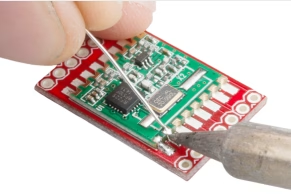
Manual soldering is suitable for prototyping, low-volume production, or rework:
- Prepare Surfaces:Ensure both the module’s castellations and the host board’s pads are clean and properly fluxed.
- Secure Module:It’s often helpful to tack one or two corners of the module first to hold it in place.
- Apply Solder:Use a fine-tipped soldering iron at an appropriate temperature. Apply a small amount of solder to the tip and then touch it to the junction of the castellation and the host board pad. Allow the solder to flow and form a concave fillet around the castellation.
- Inspect:Visually inspect each joint for adequate solder volume, proper wetting, and a smooth, shiny appearance.
Regardless of the method, the goal when considering how to solder castellated holes is to achieve a strong, reliable, and easily inspectable solder joint that provides both electrical and mechanical integrity.
6. Key Applications of Castellated Mounting Holes
Castellated holes are found in a wide array of modern electronic products, underpinning modular design strategies across various sectors:
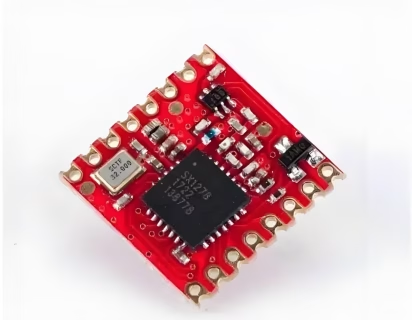
- IoT Devices:For integrating Wi-Fi, Bluetooth, LoRa, or cellular communication modules onto small sensor boards or smart devices.
- Embedded Systems:Microcontroller units(MCUs) or system-on-modules(SOMs) often use castellations for easy integration into custom baseboards.
- RF Modules:Radio frequency circuits frequently use modular designs with castellated connections to ensure consistent performance and simplify certification.
- Sensor Modules:Accelerometers, gyroscopes, environmental sensors, and other specialized sensors can be integrated as castellated modules.
- LED Driver Modules:For compact lighting solutions where driver circuits are separate, integrable modules.
7. Castellated Mounting Holes FAQs
The primary benefit is enabling modular PCB design, allowing pre-tested sub-assemblies to be easily soldered onto a main board, saving space, reducing costs, and improving reliability.
Yes, with careful design and impedance control, castellated connections can support high-speed signals, but designers must account for potential discontinuities at the module interface.
Generally, yes. The specialized routing process required to create the half-holes, along with the need for high precision, can increase manufacturing costs compared to standard PCBs.
For reflow, use appropriate solder paste volume and a suitable thermal profile. For manual soldering, ensure proper fluxing, adequate heat, and sufficient solder to form a good fillet around the castellation.
8. Summary
Castellated mounting holes represent a sophisticated yet highly effective solution for modern PCB design, facilitating the creation of compact, reliable, and modular electronic systems. Their unique half-hole structure along the board’s edge provides robust solderable connections, making them indispensable for integrating pre-tested modules like Wi-Fi radios, microcontrollers, and various sensors into larger assemblies.
While offering significant advantages in terms of space-saving, improved reliability, and simplified manufacturing processes for end products, their fabrication demands precision in drilling, plating, and especially the critical edge-routing process. Understanding these castellated hole manufacturing challenges and implementing best practices for PCB design and how to solder castellated holes are paramount to harnessing their full potential. As electronics continue to shrink and modularity becomes ever more critical, castellated holes will remain a cornerstone in advanced PCB fabrication, enabling innovation across numerous applications.
Key Takeaways
- Castellated mountingholes are plated half-holes on a PCB edge, primarily used for module integration.
- They enable modular design, reduce board size, enhance connection reliability, and can lower overall system costs.
- Careful design of pad size, drill diameter, and solder mask is essential for successful fabrication.
- Manufacturing requires high precision in drilling, plating, and edge routing, presenting unique challenges for fabricators.
- Both reflow and manual soldering methods require attention to detail to ensure strong, inspectable solder joints.
- They are widely adopted in IoT, embedded systems, and RF modules due to their flexibility and performance benefits.

Get Quote Free