
Why DIP Plug-in Soldering Still Matters in Modern PCBA?
DIP plug-in soldering, complementing SMT in modern PCBA, is essential for components needing mechanical strength, higher power, or specific form factors, involving meticulous steps from preparation to inspection.
Get Your PCB Quote!
Table of Contents

In the intricate world of electronics manufacturing, Printed Circuit Board Assembly (PCBA) is a cornerstone process. While Surface Mount Technology (SMT) has revolutionized component miniaturization and high-density boards, Through-Hole Technology (THT) components, particularly Dual In-line Package ( DIP) components, remain indispensable for many applications. The process of DIP plug-in soldering is a critical phase in PCBA production, ensuring robust mechanical and electrical connections for components that require greater physical strength, higher power handling, or specific mechanical interfaces .
This comprehensive guide delves into the entire process of PCBA DIP plug-in soldering, from initial component preparation and installation through wave soldering, post-soldering, cleaning, and final inspection. We will explore the critical steps , common challenges, best practices for quality control, and the synergistic relationship between DIP and SMT in modern PCBA manufacturing.
1. DIP Plug-in Soldering: A Foundation of PCBA
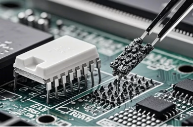
DIP plug-in components, characterized by their leads passing through holes in the Printed Circuit Board (PCB), are foundational elements for many electronic devices. Unlike their SMT counterparts that sit on the surface, DIP components are soldered on the opposite side of the board, providing a stronger mechanical bond and often better thermal dissipation. This makes them ideal for connectors, power components, larger integrated circuits, and components subject to mechanical stress.
The role of DIP plug- in soldering in Printed Circuit Board Assembly is to securely and reliably connect these components to the PCB, ensuring proper electrical conductivity and mechanical integrity. This process demands precision and adherence to strict quality standards to prevent defects that could compromise the final product’s performance and longevity.
2. The Meticulous Journey: Steps in DIP Plug-in Soldering
The PCBA DIP plug-in soldering process is a multi-stage operation, each step critical for achieving a high-quality final product. Understanding and meticulously executing each phase is paramount for successful PCBA manufacturing.
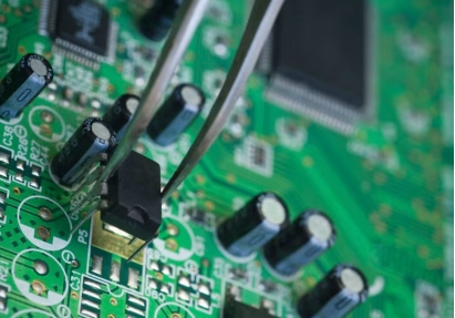
2.1 Component Preparation and Plug-in Installation
Before any soldering takes place, components must be carefully prepared and inserted into the PCB. This stage is crucial for preventing issues down the line.
- Material Preparation:This involves verifying the Bill of Materials (BOM), inspecting components for damage, and ensuring all required parts are present. Correct component orientation and polarity checks are vital.
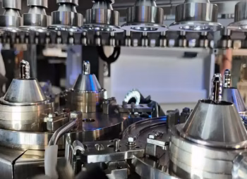
- Component Forming:Leads of through-hole components often need to be bent or cut to precise lengths to ensure proper insertion and fit. Specialized forming machines or manual tools are used for this.
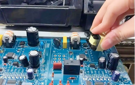
- Manual or Automated Insertion:While some smaller DIP components can be automatically inserted, many through-hole components, especially those with irregular shapes or high pin counts, require manual plug-in installation. Operators must ensure components are correctly placed, seated, and oriented according to design specifications. Fixtures may be used to hold components in place prior to soldering.
- Pre-Solder Inspection:A quick visual check after insertion confirms correct component placement and lead protrusion.
2.2 Wave Soldering
Wave soldering is the primary method for soldering multiple DIP components simultaneously. It’s an automated process that involves several critical stages:
1) Flux Application: The PCB first passes over a flux sprayer. The flux cleans the metal surfaces by removing oxides and preventing re-oxidation during the soldering process, promoting good solder wetting.
2) Preheating: The board then enters a preheating zone, gradually raising its temperature and activating the flux. This prevents thermal shock when the board contacts the molten solder and helps to evaporate volatile components of the flux.
3) Wave Soldering: The preheated PCB passes over a wave of molten solder. The solder wave contacts the exposed leads and pads, forming solder joints through capillary action. Key parameters like solder pot temperature, wave height, and conveyor speed are critical for quality.
The following table summarizes key wave soldering process parameters:
| Stage | Description | Critical Parameters | Impact on Quality |
| Flux Application | Applies flux to clean component leads and pads, preventing oxidation and aiding wetting. | Flux type, quantity, uniformity. | Ensures good solder wetting, prevents shorts and voids. |
| Preheating | Raises PCB and component temperature gradually to activate flux and prevent thermal shock. | Preheat temperature profile, zone lengths. | Prevents thermal stress, optimizes flux activity, prepares for optimal wetting. |
| Wave Soldering | PCB passes over a molten solder wave, forming joints. | Solder pot temperature, wave height, conveyor speed. | Forms strong, reliable solder joints; critical for defect prevention. |
2.3 DIP Plug-in Post-Soldering and Rework
Not all components are suitable for wave soldering. Heat-sensitive components, connectors with large masses, or components placed too close to others might require manual post-soldering. This stage also covers rework for any identified defects.
- Manual Soldering:Skilled operators use soldering irons to hand-solder specific components. Precision and consistent heat application are vital to create strong, shiny, and void-free solder joints.
- Rework:If defects are found during inspection, they are addressed in the rework station. This involves desoldering faulty components or correcting poor joints using specialized tools. Proper techniques are essential to avoid damaging the PCB or adjacent components.
2.4 Cleaning
After soldering, flux residues can remain on the PCB. These residues can be corrosive, reduce electrical insulation, or interfere with subsequent processes. Cleaning is therefore a critical step.
- Methods:Common cleaning methods include ultrasonic cleaning, solvent cleaning, or aqueous cleaning, depending on the type of flux used (no-clean, rosin-based, water-soluble).
- Importance:Proper cleaning ensures long-term reliability, prevents corrosion, and maintains the electrical performance of the assembly.
2.5 Quality Inspection and Testing
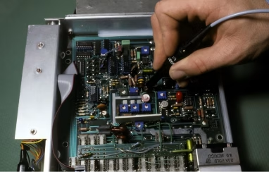
Thorough inspection is crucial to identify and rectify any defects before the PCBA moves to the next stage or final product assembly. This is an integral part of PCBA production quality control.
- Visual Inspection:Operators visually check each solder joint for common defects such as bridging (shorts), cold solder joints, insufficient solder, excessive solder, and correct component polarity.
- Automated Optical Inspection (AOI):For higher volume production, AOI systems can quickly and accurately detect common soldering defects, significantly improving inspection efficiency.
- Functional Testing:After initial inspections, the PCBA undergoes functional testing to ensure it operates as designed.
3. Ensuring Excellence: Best Practices and Quality Control
Maintaining high quality throughout the DIP plug-in soldering process is paramount. Several factors contribute to achieving robust and reliable Printed Circuit Board Assembly.
- Adherence to IPC Standards:International standards like IPC-A-610 (Acceptability of Electronic Assemblies) provide guidelines for solder joint quality and component placement, acting as a benchmark for acceptability.
- Skilled Operators:Especially for manual plug-in installation and post-soldering, highly trained and experienced operators are essential. Continuous training helps maintain skill levels and awareness of best practices.
- Equipment Calibration and Maintenance:Regular calibration of wave soldering machines, preheaters, and soldering irons ensures consistent and optimal operating parameters. Preventative maintenance reduces unexpected failures.
- Process Control:Monitoring and controlling critical parameters (e.g., temperatures, speeds, flux levels) throughout the process helps maintain consistency and identify deviations early.
- Material Quality:Using high-quality PCBs, components, solder, and flux from reputable suppliers significantly reduces the likelihood of defects.
Here are some common DIP plug-in soldering defects, their causes, and remedies:
| Defect | Description | Common Causes | Remedy/Prevention |
| Bridging/Shorts | Solder forms unintended connections between leads. | Excessive solder, insufficient flux, incorrect component spacing, poor wave profile. | Optimize solder wave parameters, use appropriate flux, ensure proper lead spacing. |
| Cold Solder Joints | Dull, grainy, or frosty appearance; poor electrical connection. | Insufficient heat, contaminated surfaces, component movement during cooling. | Ensure proper soldering iron temperature, adequate preheating, clean surfaces. |
| Insufficient Solder/Voids | Not enough solder to form a strong joint, or air pockets within solder. | Insufficient flux, incorrect solder paste volume (for SMT analogy, but also applies to wave fill), lead contamination. | Adjust flux application, optimize wave parameters, ensure lead cleanliness. |
| Excessive Solder | Too much solder, often forming large blobs. | Over-application of solder, incorrect wave height, slow conveyor speed. | Adjust wave height, optimize conveyor speed, control manual solder application. |
| Lifted Pads/ Delamination | Solder pad separates from the PCB substrate. | Overheating, improper handling, excessive rework. | Control soldering temperatures, gentle handling, appropriate tip selection for rework. |
4. DIP and SMT: A Symbiotic Relationship
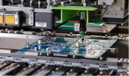
In modern PCBA production, it’s rare to find a board made exclusively with either DIP or SMT components. Instead, a hybrid approach is often employed. SMT Placement allows for high component density and automated assembly of small, intricate parts. Following SMT reflow soldering, DIP components are typically inserted and wave soldered or manually soldered. This “mixed technology” approach leverages the strengths of both, achieving optimal performance, cost-effectiveness, and design flexibility for complex electronic systems.
5. Essential Equipment for DIP Soldering
Effective DIP plug-in soldering relies on a range of specialized equipment:
- Wave Soldering Machine:The centerpiece for automated DIP soldering.
- Soldering Irons and Stations:For manual DIP plug-in post-soldering and rework.
- Component Forming Machines:To prepare component leads.
- Cleaning Equipment:Ultrasonic baths, solvent sprayers, or aqueous wash systems.
- Inspection Tools:Magnifying lamps, microscopes, and AOI machines.
- Test Fixtures:For functional testing of the assembled PCBs.
6. DIP Plug-in Soldering FAQs
DIP components offer greater mechanical strength, better power handling capabilities, and are often easier to rework. They are essential for connectors, large ICs, and components that might experience physical stress, complementing SMT rather than being replaced by it.
Common defects include solder bridging (shorts), cold solder joints (poor wetting), insufficient solder, excessive solder, and tombstoning (though more common in SMT, similar issues can arise). These often stem from improper temperatures, flux application, or component placement.
Proper component preparation, including lead forming and polarity checks, is critical. Incorrectly formed leads can lead to poor insertion, misalignment, and insufficient solder penetration, while incorrect polarity can cause immediate circuit failure.
Flux is crucial for cleaning the metal surfaces (component leads and PCB pads) by removing oxides before soldering. This ensures proper wetting of the solder to the surfaces, facilitating the formation of strong and reliable electrical and mechanical connections.
7. Summary
The Printed Circuit Board Assembly DIP plug-in soldering process is a cornerstone of electronics manufacturing, vital for creating robust and reliable electronic products. From the meticulous preparation and insertion of through-hole components to the precision of wave soldering, and the subsequent stages of post-soldering, cleaning, and inspection, each step demands careful execution. Adherence to quality standards, skilled labor, and proper equipment are indispensable for mitigating common defects and ensuring the longevity and performance of the assembled PCBs. In the dynamic landscape of PCBA production, DIP plug-in soldering continues to hold its ground, often working in conjunction with SMT to deliver highly functional and resilient electronic devices.
Key Takeaways
- DIP plug-in soldering is essential for components requiring mechanical strength, higher power, or specific form factors, complementing SMT in modern PCBA.
- The process involves meticulous steps: component preparation, plug-in installation, wave soldering (or selective soldering), post- soldering/rework, cleaning, and thorough inspection.
- Quality control is paramount, relying on adherence to IPC standards, skilled operators, equipment maintenance, and rigorous process control to prevent defects like bridging and cold solder joints.
- Wave soldering parameters (flux, preheat, solder wave) are critical for successful automated soldering, while manual soldering addresses heat-sensitive or complex components.
- Hybrid PCBA approaches, combining SMT and DIP, leverage the strengths of both technologies for optimal performance in complex electronic designs.
Table of Contents

Get Your PCB Quote!


