Circuit Board Components: How to Identify, Test & Choose
Resistors, capacitors, ICs, diodes — learn how to identify each component by appearance, test it with a multimeter, and choose the right spec for your PCB design.
Get Your PCB Quote!
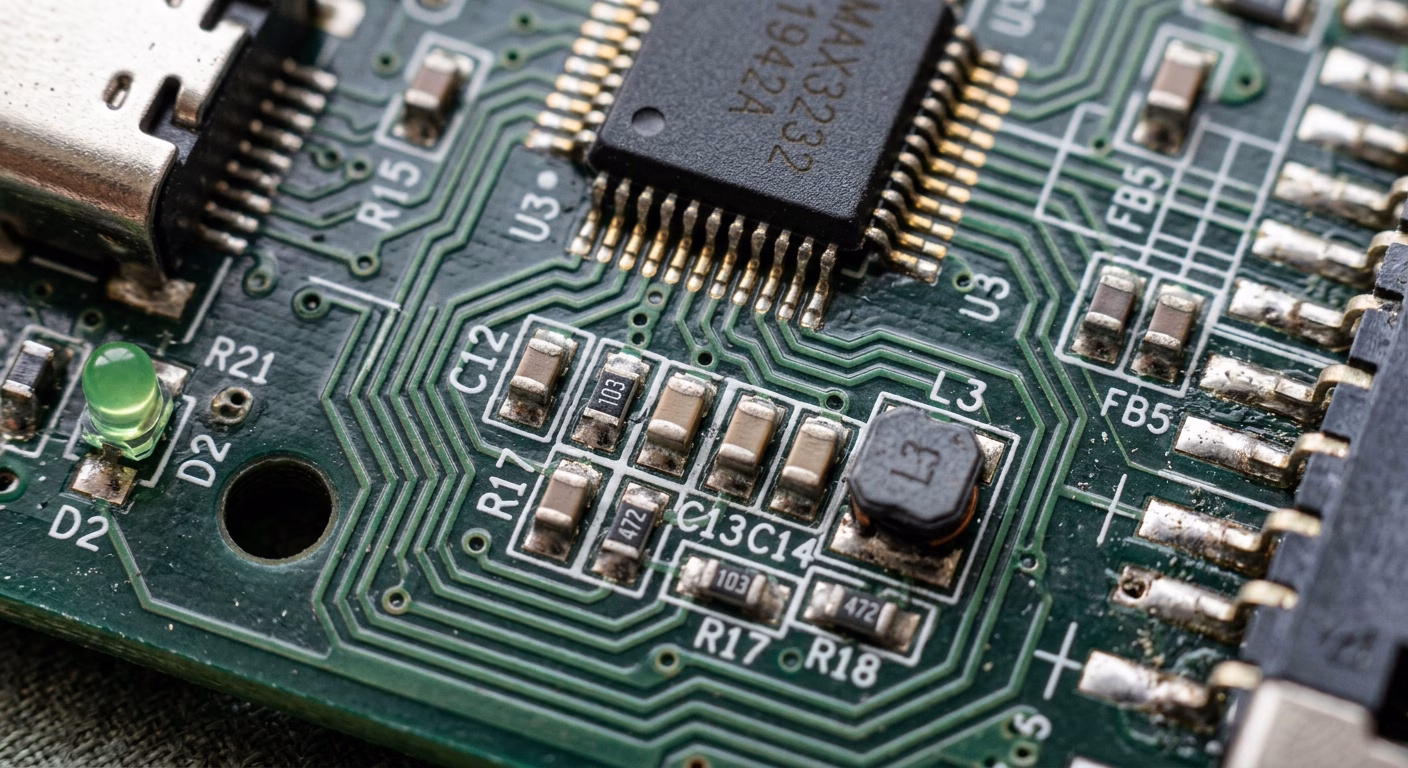
Table of Contents
- 1. Giới thiệu
- Các nội dung chính
- 2. Nền tảng: Hiểu về mạch in
- 3. Các thành phần thiết yếu của bo mạch chủ: Nhận dạng và chức năng
- 4. Giải mã các ký hiệu và dấu hiệu trên linh kiện
- 5. Lựa chọn linh kiện phù hợp: Các tiêu chí lựa chọn quan trọng
- 6. Các phương pháp tốt nhất để lựa chọn linh kiện
- 7. Cách nhận biết các linh kiện trên bo mạch điện tử
- 8. Các thành phần bổ sung đáng biết
- 9. Kiểm tra các linh kiện trên bo mạch chủ
- 10. Tháo lắp và thay thế linh kiện một cách an toàn
- 11. Nguồn cung cấp linh kiện mạch in:
- 12. Câu hỏi thường gặp
- 13. Tóm tắt thông tin
1. Introduction
Every electronic device, from the simplest toy to the most complex supercomputer, relies on a sophisticated network of tiny components mounted on a circuit board. Understanding these intricate building blocks—how to identify them, what their functions are, and critically, how to choose the right ones—is fundamental for anyone involved in electronics, whether hobbyist, student, or professional engineer.
Key Takeaways
- Accurate identification of circuit board components (resistors, capacitors, ICs, etc.) is fundamental to understanding and working with electronics.
- Component markings (color codes, numeric values, polarity indicators) and schematic symbols are crucial for both identification and circuit analysis.
- Component selection is a multi-faceted process requiring careful consideration of electrical specifications (voltage, current , power, frequency).
- Environmental factors such as temperature, humidity, and vibration significantly impact component reliability and must be accounted for during selection.
- Physical characteristics (package type, size) and performance metrics (tolerance, stability , lifespan) influence manufacturing and long-term functionality.
- Cost, availability, and compliance with industry standards are practical considerations that shape the viability of a design.
- Always consult datasheets, prototype designs, and consider alternative sourcing to ensure optimal component selection.
- Reference designators (R, C, L, D, Q, U, J, T, etc.) silkscreened on the PCB provide a direct link to the schematic and BOM, making component identification and cross-referencing faster and more reliable.
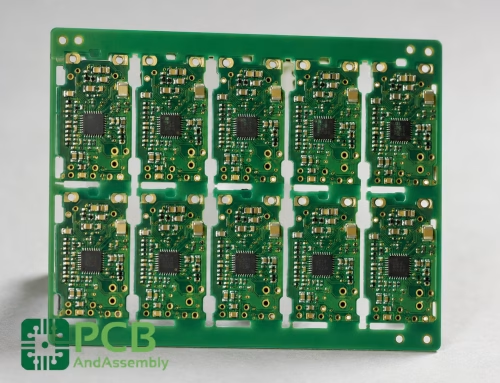
2. The Foundation: Understanding Circuit Boards
Before diving into individual components, it ‘s essential to understand the canvas they operate on: the Printed Circuit Board (PCB). A PCB serves as the mechanical support and electrical connection platform for electronic components. It consists of layers of non-conductive substrate material (like fiberglass) interspersed with conductive pathways, or traces, typically made of copper. Components are soldered onto designated pads on these traces, creating a functional circuit.
PCBs come in various forms:
- Single-sided PCBs:Conductive traces on only one side. Simple and cost-effective.
- Double-sided PCBs:Traces on both sides, with connections between layers made via holes (vias).
- Multi-layer PCBs:Multiple layers of traces separated by insulation, offering higher density and complexity.
- Flexible PCBs (Flex PCBs):Built on flexible plastic substrates, allowing circuits to bend and conform to irregular shapes.
- Rigid-Flex PCBs:Combine rigid and flexible board technologies.
3. Essential Circuit Board Components: Identification and Function
Circuit boards are populated with a diverse array of electronic components, each performing a specific role. Accurate identification is the first step towards understanding a circuit.
Resistors
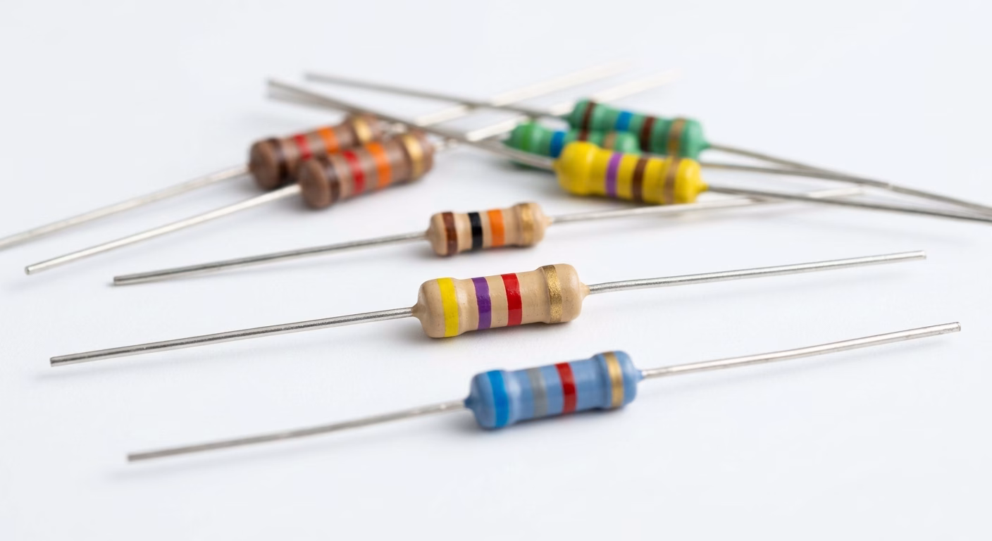
Resistors are passive two-terminal components that impede the flow of electric current. They are crucial for controlling current, dividing voltage, and terminating transmission lines. They appear as small, often cylindrical or rectangular, components with color bands or numerical codes.
- Identification:Color bands (for through-hole) or numeric codes (for SMD). Common values range from ohms (Ω) to megaohms (MΩ).
- Function:Limit current, divide voltage, pull-up/pull- down.
- Types:Carbon film, metal film, wirewound, surface-mount (SMD).
Capacitors
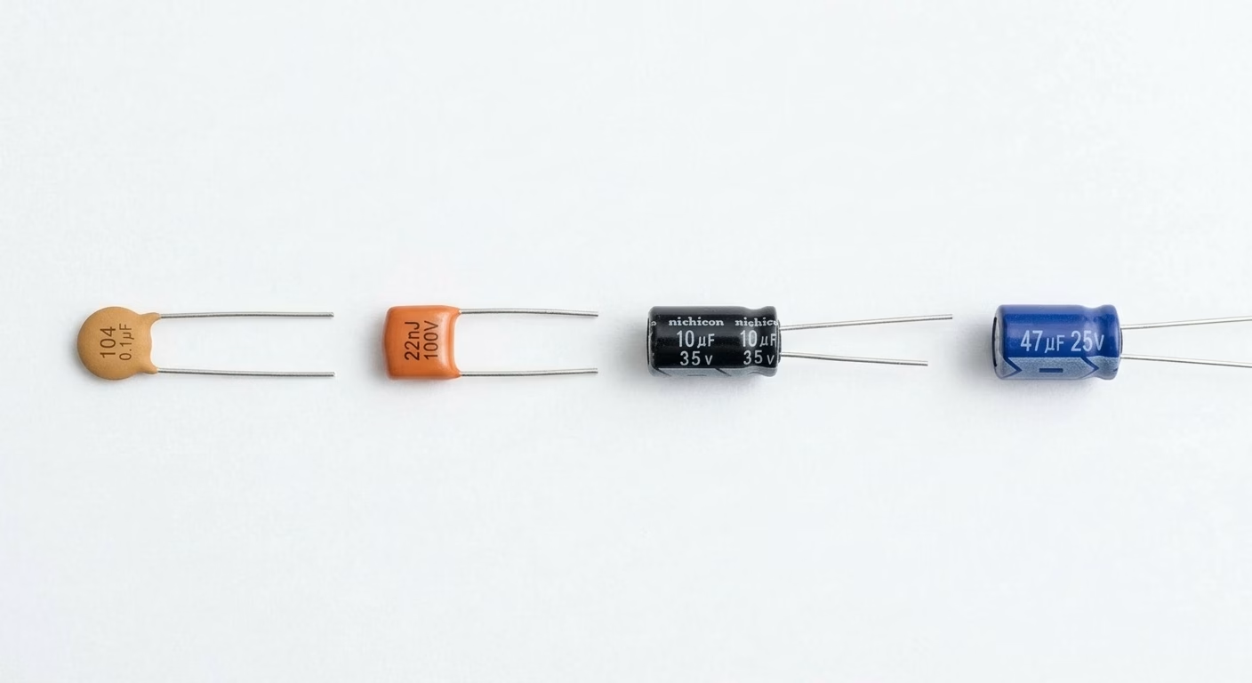
Capacitors are passive two-terminal components that store electrical energy in an electric field. They block DC current while allowing AC current to pass, making them vital for filtering, timing, and energy storage applications.
- Identification:Often cylindrical (electroly tic) or small rectangular/disc-shaped (ceramic). Marked with capacitance value (e.g., µF, nF, pF) and voltage rating. Electrolytic capacitors are polarized and have a stripe indicating the negative terminal.
- Function:Store energy, filter noise, smooth power supplies, timing.
- Types:Electrolytic, ceramic, tantalum, film.
Inductors
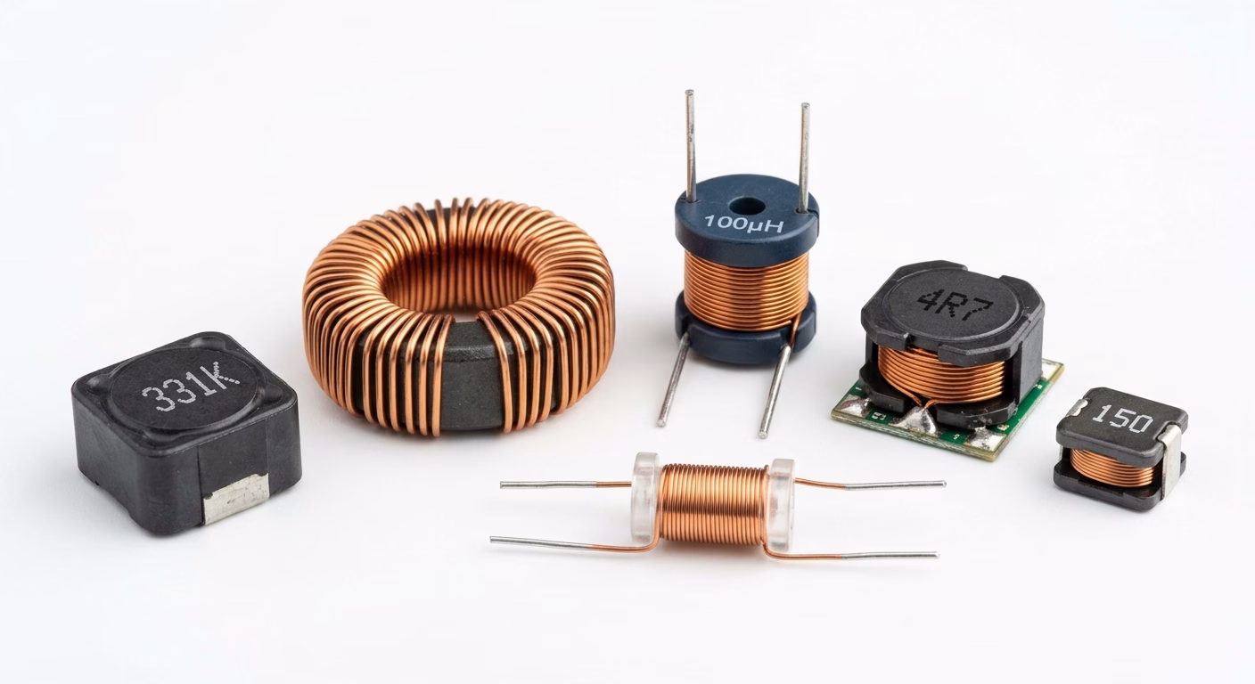
Ind uctors are passive two-terminal components that store energy in a magnetic field when current flows through them. They oppose changes in current and are used for filtering, energy storage in power converters, and RF applications.
- Identification:Often appear as coils of wire, sometimes encapsulated or toroidal. Marked with inductance in Henries (H).
- Function:Store energy in a magnetic field, filter AC signals, impedance matching.
- Types:Air core, ferrite core, toroidal, chip inductors.
Diodes
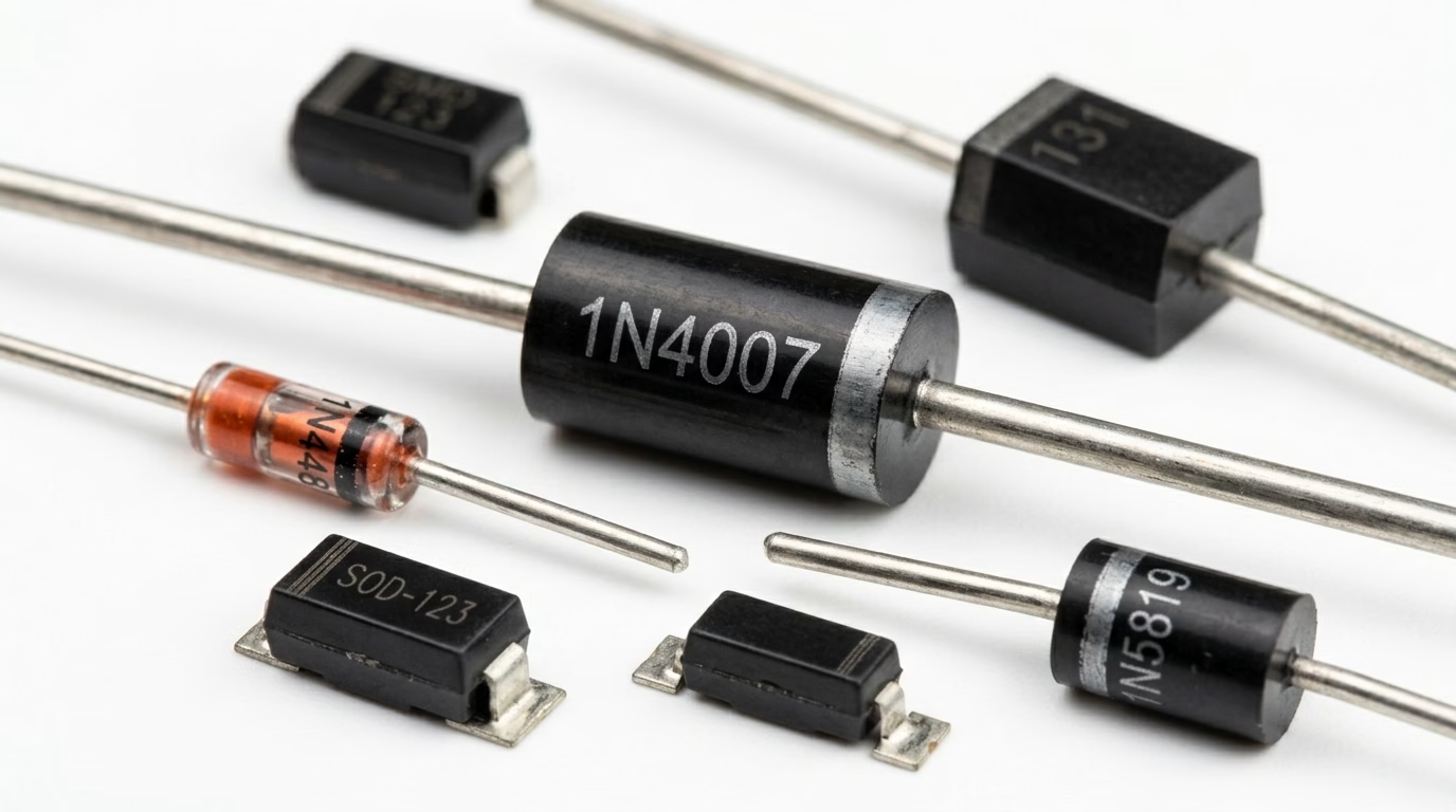
Diodes are two-terminal semiconductor devices that allow current to flow predominantly in one direction. They are fundamental for rectification, voltage regulation, and protection.
- Identification:Typically cylindrical with a band indicating the cathode (-ve) terminal. LEDs (Light Emitting Diodes) are easily recognizable by their light emission.
- Function:Rectify AC to DC, voltage regulation (Zener), signal switching, light emission (LED).
- Types:Rectifier, Zener, Schottky, LED, phot odiode.
Transistors
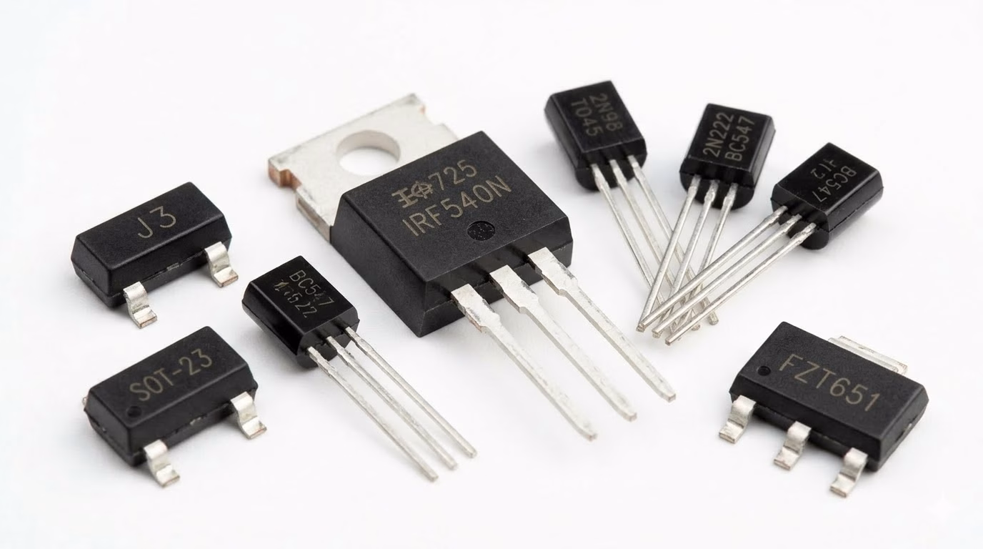
Transistors are semiconductor devices used for amplifying or switching electronic signals and electrical power. They are the fundamental building blocks of modern electronic circuits.
- Identification:Usually three-terminal devices, ranging from small plastic packages (e.g., TO-92) to larger metal or plastic power packages (e.g., TO-220, SOT-23 for SMD).
- Function:Amplification, switching.
- Types:Bipolar Junction Transistors (BJTs), Field-Effect Transistors (FETs – MOSFETs, JFETs).
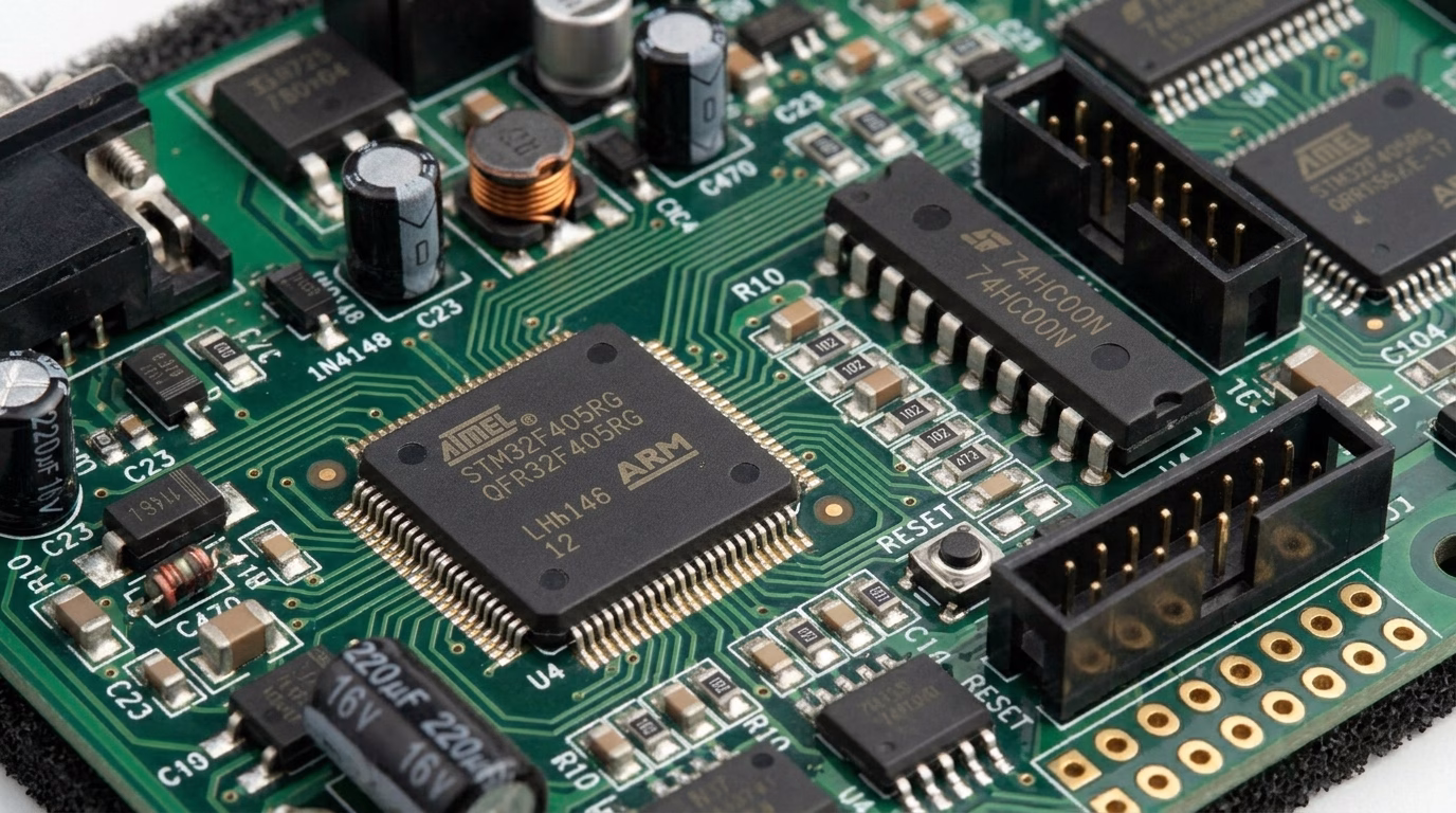
Integrated Circuits (ICs)
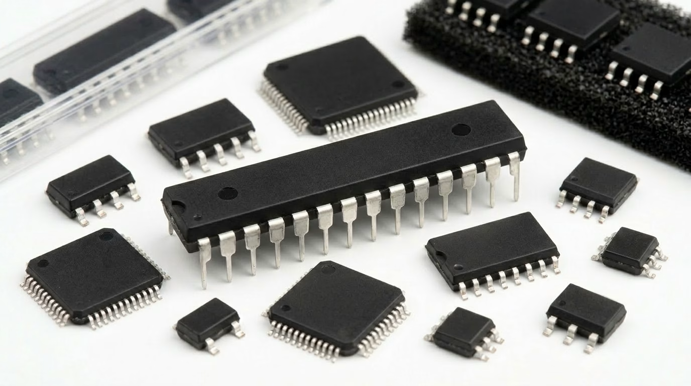
Integrated Circuits are miniature electronic circuits containing a multitude of transistors, resistors, and capacitors fabricated onto a single semiconductor substrate, typically silicon. They perform complex functions and are the ” brains” of many devices.
- Identification:Rectangular chips with multiple pins (leads) on the sides or bottom. Often marked with a manufacturer logo, part number, and sometimes a date code.
- Function:Microcontrollers, operational amplifiers (op-amps), memory chips, logic gates, voltage regulators.
- Types:Digital, analog, mixed-signal.
Connectors and Sockets
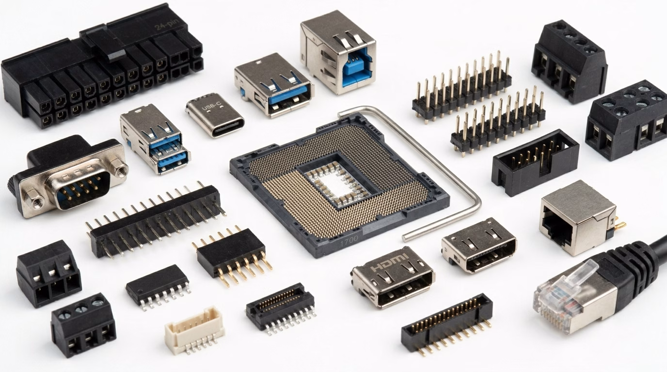
These components provide interfaces for connecting the circuit board to other boards, peripherals, power sources, or programming tools.
- Identification:Various shapes and sizes, designed for specific cable types (USB, HDMI, Ethernet, power jacks) or inter-board connections (pin headers, edge connectors).
- Function:External interfaces, modularity, test points.
Switches and Buttons
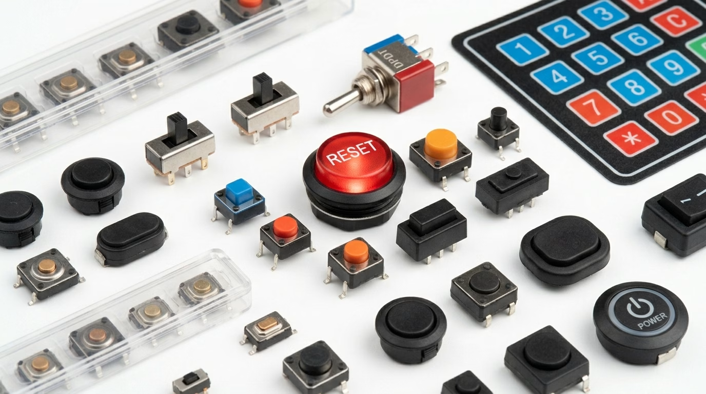
Used to control the flow of current manually, allowing users to interact with the device.
- Identification:Pushbuttons, toggle switches, slide switches, DIP switches.
- Function :On/off control, input signals.
Other Common Components
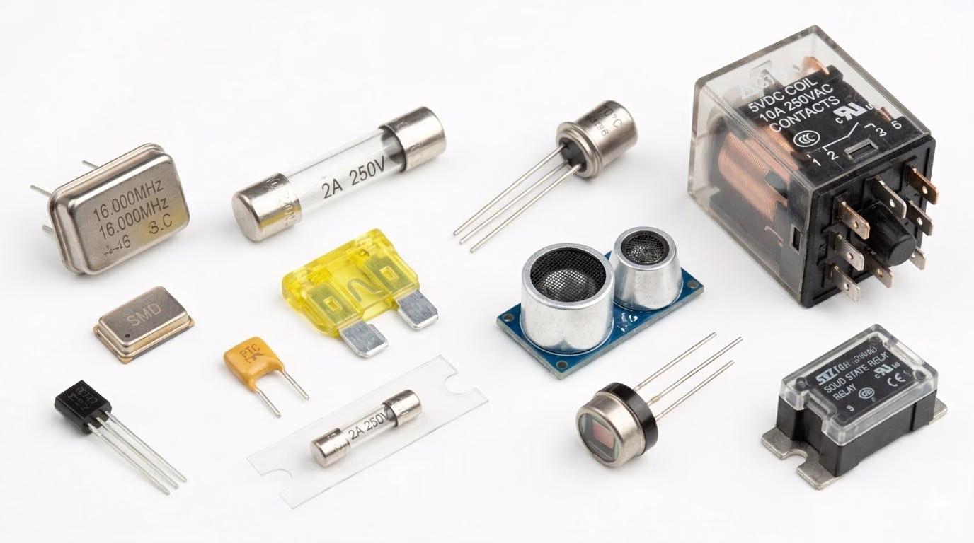
- Crystals/Oscillators:Provide a stable clock signal for microcontrollers and other digital circuits. Often small metal cans or ceramic packages.
- Fuses:Safety devices that break a circuit when current exceeds a safe level, protecting other components.
- Sensors:Convert physical phenomena (light, temperature, pressure ) into electrical signals.
- Relays:Electrically operated switches, allowing a low-power signal to control a high-power circuit.
4. Deciphering Component Markings and Symbols
Understanding the markings on components and their schematic symbols is critical for both identification and circuit analysis.
Component Markings
- Resistors:Color code bands (4, 5, or 6 bands) for through-hole, or 3-4 digit numeric codes for SMD.
- Capacitors:Numeric codes (e.g., “104” means 100n F), direct value (e.g., “47µF”), or a letter/number code for tolerance and voltage. Electrolytics have polarity indicators.
- Diodes:Part numbers and a band indicating the cathode.
- Integrated Circuits (ICs):Manufacturer logo, part number (e.g., “ATmega328P”, “LM358”), and often a date code. Pin 1 is usually marked with a dot, notch, or corner chamfer.
- Transistors:Part numbers (e.g., “2N2222”, “BC547”) and package type.
Schematic Symbols
Each component has a standardized symbol used in circuit diagrams. Familiarity with these symbols allows for quick interpretation of circuit functionality without needing to see the physical board.
| Component | Common Symbol | Brief Function |
| Resistor | Zig-zag line or rectangle | Limits current |
| Capacitor | Two parallel lines (one curved for polarized ) | Stores charge, filters |
| Inductor | Coiled line | Stores energy in magnetic field |
| Diode | Triangle with a line | Allows current one way |
| LED | Diode symbol with arrows pointing out | Emits light |
| Transistor (NPN) | Circle with three leads (base, emitter, collector) and arrow | Amplifies/ switches |
| Integrated Circuit | Rectangle with pin labels | Performs complex functions |
| Switch (SPDT) | Open circuit line with moving arm | Opens/closes circuit |
5. Choosing the Right Parts: Key Selection Criteria
Selecting the appropriate components is paramount for a circuit’s performance, reliability, and cost-effectiveness. A systematic approach is crucial.
Electrical Specifications
- Voltage Ratings:Ensure components can withstand the maximum voltage present in the circuit, including transients. Always allow for a safety margin (e.g., 20-50% higher than operating voltage).
- Current Ratings:Verify components can handle the maximum expected current without overheating or failure. This is critical for resistors, inductors, transistors, and connectors.
- Power Ratings:For components like resistors, ensure their power dissipation rating (in Watts) exceeds the calculated power dissipated by them in the circuit.
- Frequency Response:For AC and high-frequency applications, components must be selected based on their ability to operate effectively at the required frequencies (e.g., certain capacitors, inductors, and ICs have frequency limitations).
- Impedance:Important for RF circuits and signal integrity, ensuring matched impedance to prevent signal reflections.
Environmental Factors
- Operating Temperature Range:Electronics often operate in diverse environments. Components must be rated for the expected ambient temperature range. Extreme temperatures can drastically reduce component lifespan or cause immediate failure.
- Humidity and Moisture Resistance:In humid environments, components may require special coatings or encapsulation to prevent corrosion and short circuits .
- Vibration and Shock:For applications in vehicles, industrial machinery, or portable devices, components must withstand mechanical stress. Package type and mounting method become critical.
- EMI/EMC (Electromagnetic Interference/Compatibility):Select components that either minimize EMI generation or are robust enough to withstand external EMI without malfunction.
Physical Characteristics
- Package Type (SMD vs. Through-hole):Surface Mount Devices (SMD) are smaller, allowing for denser boards, automated assembly, and lower cost in high volume. Through-hole components are easier for prototyping and manual soldering, and often more robust mechanically.
- Size and Footprint:The physical dimensions of a component must fit within the available space on the PCB. Footprint refers to the pattern of pads/holes on the PCB for a component.
- Pin Count and Spacing:For ICs and connectors, the number of pins and their pitch (spacing) must match the design requirements.
Performance and Reliability
- Tolerance:The allowable deviation from a component’s nominal value (e.g., a 100Ω resistor with 5% tolerance can be between 95Ω and 105Ω). Tighter tolerances are often more expensive.
- Stability:How much a component’s value changes over time, temperature, or other environmental stresses. Critical for precision applications.
- Lifespan/MTBF (Mean Time Between Failures):Important for high-reliability systems, especially with components like electrolytic capacitors which have a finite lifespan.
- Noise Characteristics:Some components (e.g., certain resistors, op-amps) inherently generate more electrical noise than others. Critical for sensitive analog circuits .
Cost and Availability
- Budget Constraints:Component cost can significantly impact the overall product cost, especially in high-volume manufacturing.
- Lead Times and Supply Chain:Ensure chosen components are readily available from multiple suppliers, reducing the risk of production delays due to shortages. Avoid single-source components where possible.
- End-of-Life (EOL) Status:Avoid using components that are nearing their end-of-life, as replacements may become difficult to source.
Application-Specific Needs
- Compliance & Certifications:For certain industries (medical, automotive, aerospace), components must meet specific regulatory standards (e.g., AEC-Q for automotive, RoHS compliance for hazardous substances).
- Power Efficiency:For battery-powered devices, selecting low-power consumption components is critical.
- Software/Firmware Compatibility:For microcontrollers and programmable ICs, ensure compatibility with your chosen development tools and libraries.
6. Best Practices for Component Selection
- Read Datasheets Thorough ly:The datasheet is your primary source of information, providing all critical electrical, mechanical, and environmental specifications.
- Consult Application Notes:Manufacturers often provide application notes that demonstrate best practices and common pitfalls for using their components .
- Utilize Component Libraries and CAD Tools:Use established component libraries in your PCB design software to ensure correct footprints and symbols.
- Prototype and Test:Always build and thoroughly test prototypes to validate component performance in the actual circuit environment.
- Consider Second Sourcing:Identify alternative components from different manufacturers with similar specifications to mitigate supply chain risks.
- Engage with Distributors:Major electronics distributors can offer valuable advice, stock information, and sometimes even technical support.
7. How to Identify the Components on a Circuit Board
Being able to recognize what you’re looking at on a PCB is one of the most practical skills in electronics. Whether you’re troubleshooting a fault, planning a repair, or simply trying to understand how a device works, a systematic approach makes the process far more reliable than guessing from appearance alone. The five steps below walk you through identifying components from the broadest level down to individual part markings.
Step 1: Determine the Board’s Purpose
Before zooming in on individual parts, step back and ask what the board is actually for. Check for any model numbers, brand names, or functional labels silk-screened on the board surface — these often reveal whether you’re dealing with a power supply, a motor controller, a communication module, or a main logic board. Different application categories tend to use predictable component mixes: a switching power supply will be dominated by inductors, MOSFETs, and bulk capacitors, while a microcontroller board centers around an IC with supporting passives. Knowing the context narrows your expectations considerably before you examine a single component.
Step 2: Inspect Passive Components in Detail
Resistors, capacitors, and inductors are the easiest entry point because their physical forms are highly consistent across manufacturers. Resistors stand out through their color band system — each ring encodes a digit or multiplier — though SMD versions use a compact 3- or 4-digit printed code instead. Capacitors split into two visually distinct groups: upright cylindrical cans (electrolytics) with a printed value and polarity stripe, and flat rectangular or disc-shaped ceramics with a stamped code. Inductors are recognizable by their coiled wire construction, often on a ferrite core, and carry the designator L on the board. Starting with passives builds a solid reference point for the rest of the board.
Step 3: Carefully Evaluate Integrated Circuits
ICs deserve the most careful attention because they carry the highest functional complexity on any board. Most modern ICs have a manufacturer part number printed on the package — searching that string in a datasheet database will tell you exactly what the chip does, its pin assignments, and its operating conditions. Older or generic ICs sometimes use abbreviated functional codes (such as 7400 for a quad NAND gate) rather than a full part number, but these are equally searchable. Pay close attention to pin 1 orientation, usually marked by a dot, notch, or chamfered corner, since incorrect re-installation of a polarized IC can cause immediate damage.
Step 4: Identify Other Discrete Components
Beyond passives and ICs, a board typically hosts a mix of electromechanical and protection components. Transformers are identifiable by their bulk and their multiple wire windings on a magnetic core. Relays have a box-shaped housing and often make an audible click when activated, distinguishing them from solid-state components. Diodes show a polarity band at the cathode end; LEDs add a transparent or colored lens. Connectors and switches are largely self-evident from their mechanical form. For any part that resists quick recognition, the silkscreen designator nearby (T, K, J, D, SW, etc.) is your fastest shortcut to narrowing down the component type before searching further.
Step 5: Consult Reference Designators
Reference designators are short alphanumeric codes printed on the PCB silkscreen layer directly beside each component. The letter prefix tells you the component category, and the number distinguishes one instance from another on the same board (e.g., R1 and R2 are both resistors, but in different circuit positions). Cross-referencing a designator with the board’s schematic or Bill of Materials gives you the exact part specification without needing to read the component’s own markings. The table below covers the full set of standard designators you are likely to encounter.
| Designator | Component |
| ATT | Attenuator |
| BR | Bridge Rectifier |
| BT | Battery |
| C | Capacitor |
| CB | Circuit Breaker |
| CN | Capacitor Network |
| DC | Directional Coupler |
| D | Diode |
| F | Fuse |
| G | Oscillator |
| IC | Integrated Circuit |
| J | Jumper or Jack |
| K | Relay or Contactor |
| L | Inductor |
| LED | Light-emitting Diode |
| LS | Loudspeaker |
| MOV | Metal Oxide Varistor |
| P | Plug |
| POT | Potentiometer |
| PS | Power Supply |
| Q | Transistor |
| R | Resistor |
| S or SW | Switch |
| TB | Terminal Block |
| TC | Thermocouple |
| TP | Test Point |
| TR | Transducer |
| T | Transformer |
| U | Integrated Circuit |
| VR | Variable Resistor |
| X | Transducer |
| XTAL | Crystal |
| Z | Zener Diode |
| ZD | Zener Diode |
When a component still can’t be identified after working through all five steps, the most reliable next move is to pull up the full board schematic or service manual if one is available. For consumer electronics, manufacturer service documentation is often publicly accessible. If not, uploading a clear photo to an electronics forum or using a component identification app can surface answers quickly. Avoid making assumptions about an unidentified part before testing or replacing it — one misidentified component can compound a fault rather than resolve it.
8. Additional Components Worth Knowing
Beyond the core passives and semiconductors covered earlier, certain specialized components appear regularly in power electronics, industrial boards, and mixed-signal designs. Being able to recognize and understand them rounds out your component vocabulary.
Transformers
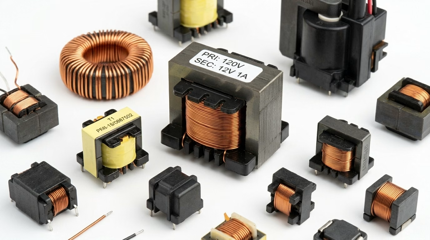
Transformers transfer electrical energy between two or more circuits through electromagnetic induction, with no direct electrical connection between them. This makes them invaluable for voltage step-up and step-down in power supplies, as well as for galvanic isolation between circuit sections.
- Identification:Ferrite or laminated iron cores wound with copper wire, often encapsulated in a rectangular or toroidal package. Generally larger and heavier than inductors.
- Function:Voltage transformation, electrical isolation, and impedance matching.
- Reference Designator:T (e.g., T1, T3).
Silicon-Controlled Rectifiers (SCRs) and Thyristors
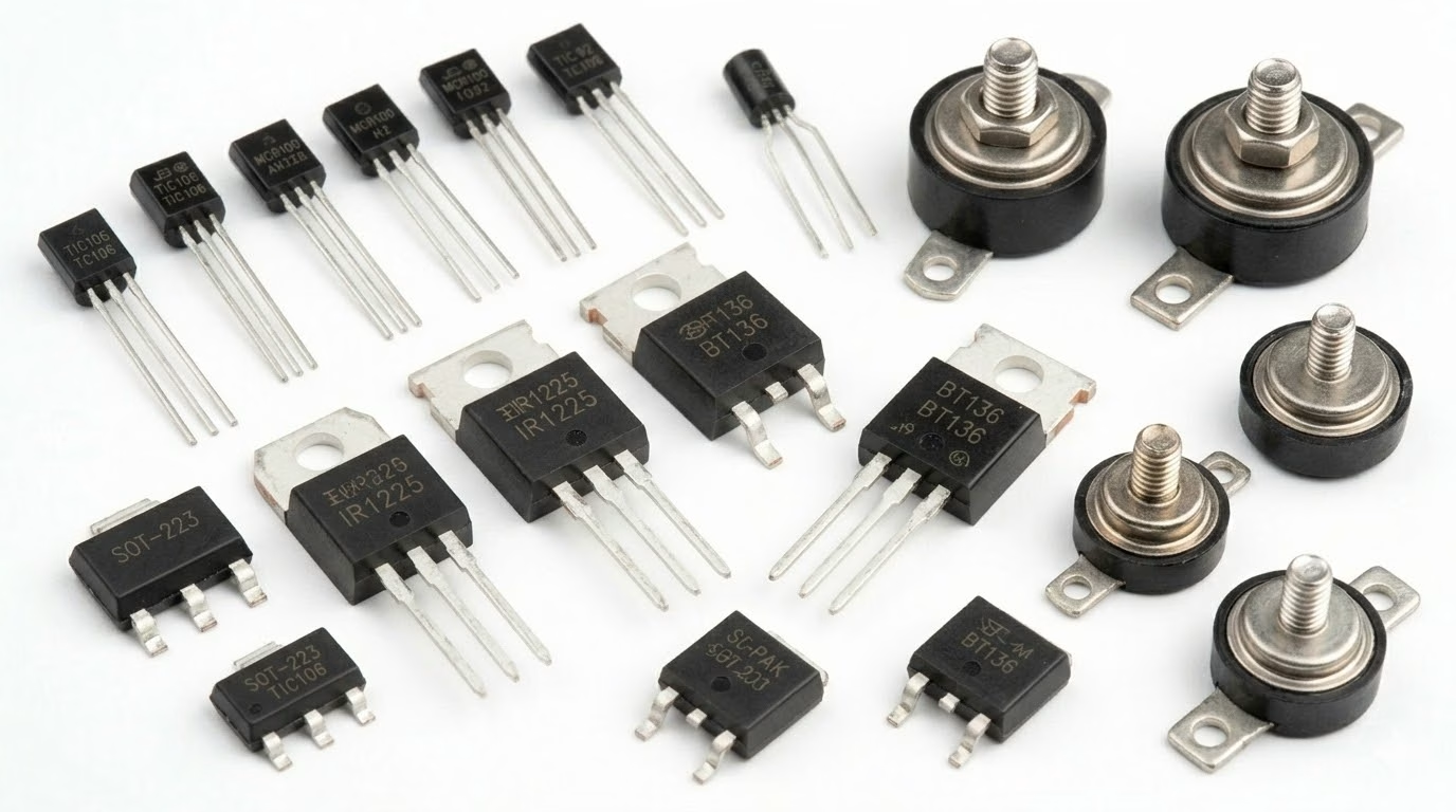
An SCR is a four-layer, three-terminal semiconductor device (anode, cathode, gate). Once triggered by a gate pulse, it conducts heavily until the current through it drops below a holding threshold. SCRs are common in motor drives, dimmers, and high-power rectifier stages where precise control of large currents is required.
- Identification:Three-terminal package similar in appearance to a power transistor (e.g., TO-220). The part number or “SCR” label is typically printed on the body.
- Function:Controlled switching and rectification of high-voltage or high-current AC/DC loads.
- Reference Designator:SCR or THY.
9. Testing Circuit Board Components
Before replacing a suspect component, always verify it is actually faulty. A digital multimeter is the most accessible and versatile tool for in-circuit and out-of-circuit testing. The following procedures cover the most common components you will encounter during diagnostics.
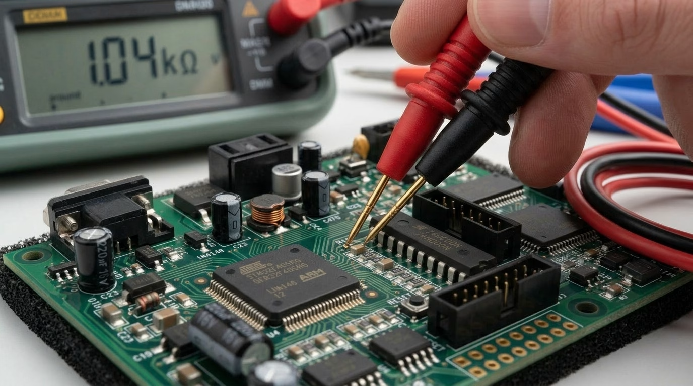
Testing Resistors
- Setup:Set the multimeter to the resistance (Ω) range that best matches the component’s rated value.
- Procedure:Place both probes across the resistor leads. The reading should be within the component’s tolerance band of its marked value.
- Fault indicators:An “OL” or infinite reading points to an open resistor; a reading near zero suggests a short circuit. Note that parallel components on a live board can skew readings—desolder one lead for a definitive measurement when in doubt.
Testing Capacitors
- Setup:Use the capacitance (F) mode on your multimeter, or an LCR meter for greater accuracy. Always discharge the capacitor fully before touching its leads.
- Procedure:Connect probes to both leads (observe polarity for electrolytics). The displayed capacitance should be close to the rated value printed on the body.
- Fault indicators:A value significantly below the rating suggests capacity loss. Near-zero resistance in resistance mode indicates a shorted capacitor. Also inspect visually for bulging tops or electrolyte leakage on through-hole electrolytics.
Testing Diodes
- Setup:Switch the multimeter to diode test mode (the diode symbol).
- Procedure:Connect the red probe to the anode and black probe to the cathode (the banded end). A functional silicon diode typically shows a forward voltage drop between 0.5 V and 0.7 V. Reverse the probes—a healthy diode will show “OL” (open).
- Fault indicators:A low voltage drop in both directions signals a shorted diode; “OL” in both directions signals an open diode. When forward-biasing an LED in diode mode, you should see it emit a faint glow.
Testing Inductors
- Setup:Use continuity or resistance mode for a quick pass/fail check; an LCR meter gives a precise inductance reading.
- Procedure:Touch the probes to both inductor terminals. A healthy winding should show very low resistance (typically under 10 Ω for most power inductors).
- Fault indicators:Infinite resistance points to a broken winding (open circuit). For thorough verification, compare the measured inductance value against the component’s datasheet specification using an LCR meter.
Recommended Testing Tools
- Digital Multimeter (DMM):The essential starting point for voltage, resistance, continuity, and diode checks.
- LCR Meter:Precisely measures inductance, capacitance, and resistance for components where tolerance matters.
- Oscilloscope:Invaluable for diagnosing signal-level issues, ripple on power rails, and timing problems in digital circuits.
- PCB Holder & Magnifying Glass:Keeps the board steady and aids visual inspection of fine-pitch SMD components for burn marks, cracks, or lifted pads.
10. Removing and Replacing Components Safely
Even with a confirmed fault, a repair can go wrong if components are removed carelessly. Lifted pads and damaged traces are far more time-consuming to fix than the original fault. The following workflow keeps the PCB intact and the new part properly installed.
Essential Tools
- Temperature-controlled soldering iron:Maintains a consistent tip temperature, preventing overheating of pads or heat-sensitive ICs.
- Desoldering pump or braid (wick):Clears molten solder from through-hole pads or fine-pitch areas before lifting the component.
- Hot-air rework station:The preferred method for SMD ICs and multi-pin packages, heating all joints simultaneously to avoid pad stress.
- Flux pen:Applying fresh flux improves solder flow, reduces bridging risk, and helps wick absorb old solder more effectively.
- Anti-static tweezers and PCB holder:ESD-safe tools protect sensitive semiconductors, while a board holder frees both hands for precise work.
Removal Procedure
- Power off and discharge:Disconnect all power and allow large capacitors to discharge fully before touching any joint.
- Apply heat and remove solder:Heat each joint in turn, then immediately clear the molten solder with a pump or braid. Repeat until the lead moves freely.
- Lift gently:Use tweezers to ease the component straight up without rocking, which can tear the pad from the board.
- Clean the pads:Remove residual flux and solder with isopropyl alcohol (IPA) and a cotton swab or PCB brush before installing the replacement.
Installation and Soldering Tips
- Verify orientation first:For polarized parts (diodes, electrolytic capacitors, ICs), confirm correct orientation against the silkscreen marking before applying any heat.
- Heat pad and lead together:Touch the iron tip to both the pad and the component lead simultaneously, then feed solder until it flows smoothly into a shiny, cone-shaped fillet.
- Minimize dwell time:Limit iron contact to 2–3 seconds per joint. Prolonged heat can delaminate the copper pad or stress nearby components.
- Inspect before powering on:Use a magnifying glass to check for solder bridges between adjacent pins, cold joints (dull, grainy surface), or incomplete wetting.
11. Where to Source Circuit Board Components
Knowing which component you need is only half the battle—finding a genuine, correctly-specified part is equally important, especially when dealing with obsolete or low-volume designs. The following channels cover the full spectrum from hobby orders to professional procurement.
PCBAndAssembly: Circuit Board Parts Supplier & PCB, PCBA Manufacturer
PCBAndAssembly is your trusted partner for professional PCB assembly and component sourcing. With 20+ years of expertise, we deliver precision you can count on.
- Capabilities: SMT & THT, supporting components down to 0201.
- Capacity:8 high-speed production lines for high-volume demands.
- Supply Chain:200k+ parts in stock with expert BOM cost-optimization.
- Quality: SPI, AOI, and X-ray inspected to IPC Class 2/3 standards.
- Compliance: ISO 9001, UL, and RoHS certified.
Send your Gerber and BOM to PCBAndAssembly now for a fast, accurate quote!
12. FAQ
Question: What is the difference between through-hole and SMD components?
Answer: Through-hole components have leads that pass through holes in the PCB and are soldered on the opposite side. SMD (Surface Mount Devices) are smaller and are soldered directly onto pads on the surface of the board. Through-hole is generally easier for prototyping, while SMD allows for higher component density and automated assembly.
Question: How do I identify the value of an SMD resistor?
Answer: SMD resistors typically use a 3 or 4-digit code. For a 3-digit code, the first two digits are the significant figures, and the third is the multiplier (number of zeros). For a 4-digit code, the first three are significant, and the fourth is the multiplier. An ‘R’ often denotes a decimal point (e.g., 102 = 1kΩ, 4R7 = 4.7Ω).
Question: Why is polarity important for some components?
Answer: Polarized components like electrolytic capacitors, diodes, and some ICs must be installed with the correct orientation. Incorrect polarity can lead to malfunction, damage to the component, or even catastrophic failure (e.g., electrolytic capacitors can explode if reverse-biased).
Question: What are the most common tools for identifying components?
Answer: A good magnifying glass or microscope, component datasheets, a multimeter (for basic checks like resistance or continuity), and familiarity with common component packages and markings are essential.
Question: How critical is the temperature rating of a component?
Answer: Extremely critical. Operating a component outside its specified temperature range can lead to significant degradation in performance, reduced lifespan, or immediate failure. High temperatures accelerate aging in most electronic components.
Question: What does a reference designator tell me?
Answer: A reference designator is a short code silkscreened next to each component on the PCB. The letter prefix identifies the component type (R = resistor, C = capacitor, U = IC, etc.) and the trailing number indicates its position in the schematic. Pairing the designator with the board’s schematic or BOM gives you the exact part specification without needing to read the component’s own markings.
Question: How do I test a component without desoldering it?
Answer: In-circuit testing is possible but must be interpreted with care, because parallel components on the same net can skew your reading. For resistors and diodes, a rough in-circuit check can still rule out gross faults like hard opens or short circuits. For capacitors, the surrounding circuitry almost always interferes enough to make the reading unreliable—desolder at least one lead for an accurate capacitance measurement.
Question: What is the difference between a transformer and an inductor?
Answer: Both use coils of wire on a magnetic core, but serve different roles. An inductor has a single winding and stores energy to filter or regulate current within one circuit. A transformer has two or more separate windings magnetically coupled together, transferring energy between circuits while stepping voltage up or down and providing galvanic isolation.
Question: Where is the safest place to buy replacement components?
Answer: Authorized distributors such as DigiKey, Mouser, Farnell, Arrow, and Avnet purchase directly from manufacturers and can provide full traceability documentation, making them the most reliable choice. Avoid sourcing critical components—especially ICs—from unverified third-party sellers, where counterfeit parts are a known risk. If a part is discontinued, check the manufacturer’s product change notice (PCN) for a recommended alternative rather than relying on appearance or partial part-number matches alone.
Question: How do I avoid lifting PCB pads when desoldering?
Answer: The two most common causes of lifted pads are excessive heat dwell time and forcing a component before the solder has fully melted. Apply fresh flux to improve heat transfer, limit iron contact to 2–3 seconds per joint, and lift the part straight out rather than rocking it sideways. For multi-pin SMD packages, a hot-air rework station heats all joints simultaneously and is far gentler on the board than working pin by pin with a contact iron.
13. Summary
Nav igating the complex world of circuit board parts requires a blend of knowledge in identification and strategic selection. From understanding the foundational role of the PCB to recognizing the myriad components—resistors, capacitors, diodes, ICs, and more—each element plays a vital part in a circuit’s operation. Deciphering component markings and schematic symbols provides the language to read and understand any electronic design.
Beyond identification, the art of choosing the right part involves a careful consideration of electrical, environmental, and physical specifications, balanced against performance, reliability, cost, and availability. Adopting best practices like rigorous datasheet review, prototyping, and strategic sourcing ensures that your electronic designs are not only functional but also robust, reliable, and cost-effective.

Get Quote Free