A Complete Guide to Circuit Card and Printed Circuit Board Assembly
Circuit card assembly (CCA) transforms PCBs into functional electronics via soldering, inspection & testing for diverse industry applications.
Get Your PCB Quote!

Table of Contents
- 1. Hva er kretskortmontering (CCA)?
- 2. Hvordan har kretskortmonteringen endret seg over tid?
- 3. Hva er noen vanlige typer kretsmontering?
- 4. Hva er noen vanlige bruksområder for kretskortmontering?
- 5. Hva er prosessen med PCB?
- 6. Vanlige problemer og løsninger med kretskort
- 7. Fordelene med produsentmontering fremfor kommisjonsmontering
This article will take you on a journey through the world of circuit card assembly, its types, applications and benefits.
You’ll understand the importance of circuit cards and their assembly by the end of this guide.
1.What is Circuit Card Assembly (CCA)?
This process, generally referred to as printed circuit board assembly (PCBA), involves mounting electronic factors onto a PCB to bring a functional electronic device to life.
Soldering resistors and capacitors onto a PCB are done using either automated machines or manually.
2.How has the circuit card assembly changed over time?

Circuit card technology has advanced significantly in the last few decades, as well as its application. In the early days, circuit cards were manually assembled and wired, which was a slow and error-prone procedure.
In the 1960s, the introduction of automated component placing machines revolutionized the electronic industry. It made the production of devices more efficient.
As time went on, improvements in materials and technology led to significant changes in the way this assembly was built. Printed Circuit Board Assembly, rigid-flex circuit board and other circuit boards that were flexible and bendable while maintaining functionality have been developed.
3.What are some common types of circuit assembly?
From functionality to performance, each circuit assembly type brings its own strengths. Explore some of the most common options:
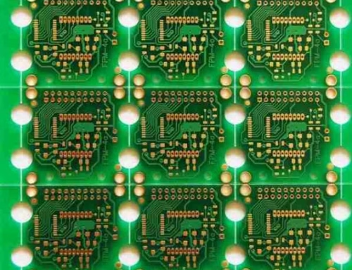
3.1Rigid Circuit Boards

The most popular circuit board type is the rigid circuit board which functions across various sectors including consumer electronics and aerospace defense. Their base material consists of rigid substrates like fiberglass or plastic and includes multiple layers to enhance functionality.
3.2Flexible Circuit Boards

Flexible circuit boards are also called flex circuits. They are made from a flexible substrate, such as PEEK or polyimide. These circuit boards are used for applications that require the board to be bent, twisted or rotated.
3.3Circuit Boards Rigid-Flex
Rigid- flex boards combine rigid and flexible circuits to produce a board that’s ideal for operations taking both rigidity and flexibility. Multiple layers of rigid and flexible materials are laminated to produce a single board.
3.4High Density Interconnect Circuit Boards (HDI)

HDI circuit boards have been designed to fit more components in a smaller area. These circuit boards feature microvias, and high density connections that allow for smaller and complex devices.
4.What are some common uses of Printed Circuit Board Assembly?
Printed board has a variety of uses, from consumer electronics to automation in the industrial sector. Take look at the most common applications.
1) Consumer Electronics
PCB board assembly can be set up in numerous consumer electronics products, similar as smartphones, tablets and laptops. The compact structure and multi-functional capabilities of circuit boards make them an excellent fit for this process.
2) Medical Devices
PCB can be set up in a wide range of medical devices similar as insulin pumps, leaders and MRI machines. Circuit boards are ideal for medical bias because of their small size and reliability.
3) Aerospace and Defense
In aerospace and defense, PCB is extensively used in operations such as avionics and radar systems. Their consistent performance and resistance to wear make circuit boards a favored choice for these operations.
4) Automobile
Circuit card assemblies contribute in ultramodern vehicles, powering essential systems like infotainment consoles and machine control units for enhanced performance and functionality. Circuit boards are ideal for this operation due to their small size and functionality.
5.What is the process of PCB?
PCB product includes several stages, including schematic design, circuit layout and printing, as well as solder paste placement, element placement and flow soldering. A thorough examination is also performed to ensure reliability and functionality.
- Designing Circuit Boards: The circuit board is designed using CAD software. The design specifies where and how the components are oriented, along with the electrical connections.
- Printing Circuit Boards: A special printer is used to print the design onto a copper coated board. The resist layer protects the area where the components will be installed.
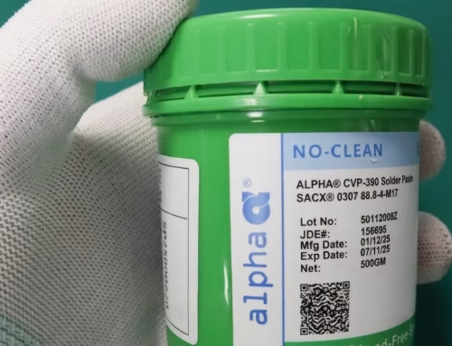
- Solder paste operation:A stencil will be used to apply solder to the PCB. The stencil is used to ensure that solder paste is applied only where demanded, on the element pads.
- Placement of Components:Formerly solder paste has been applied, the components are placed on the board. This step can be carried out by automated pick- and place machines or by professed technicians depending on the complexity of the design.
- Reflow soldering: Reflow oven is used to be passed the board The solder paste is melted and solidifies electrical and mechanical connections as the board cools.
- Inspection:The board will be inspected for any defects and to make sure that the factors have been soldered duly.
6.Common Circuit Card Issues and Solutions
There is multiple issue found while the process of assembly of circuit cards, such as component placement, soldering, and designing. In this post, you’ll find out the main causes and the important role of manufacturing
1) Soldering Issues
Soldering problems can include cold solder joints and excess solder. Inappropriate heat profiles or malfunctioning electronic parts are the main causes of repairing or production The temperature settings can be adjusted, solder paste reapplied, or faulty components replaced.
2) Component Placement Issues
Misplaced or incorrectly aligned components can be a cause of component placement problems. This is usually caused by incorrect component or setting positioning. Manually adjusting component position and adjusting machine settings are possible solutions.
3) Design Issues
These issues can be caused by incorrect design specifications, incorrect component footprints or other errors. Incorrect design files or incorrect component data can cause these issues. Revision of the design files and correction of component data are possible solutions.
7.The advantages of a manufacturer over consignment assembly
Original equipment manufacturers (OEMs) prefer PCB companies that can offer comprehensive services during the entire production cycle, rather than consignment assembly. There are many advantages to using one supplier throughout the entire production process.
This method is economical due to the lack of shipping costs and the optimization in bill of material costs, as all processes are performed under one roof. This technique also ensures quality control as it is impossible to communicate any errors made at any point in time with the next vendor.
It can be a long and expensive process to determine who is responsible, with no obvious way to correct the problem. This can be avoided by using a single provider, as the responsibility is shared and errors are corrected at every stage.
Lastly, collaborating with one point of contact allows for better communication between designers, engineering and testing teams.


Get Quote Free