Aluminum PCB: Complete Guide to Metal Core Circuit Boards
Aluminum PCB uses a metal core, such as aluminum or copper, to improve heat dissipation. Unlike traditional FR4 boards, Aluminum PCB handle higher power densities due to the metal’s high thermal conductivity.
Get Your PCB Quote!
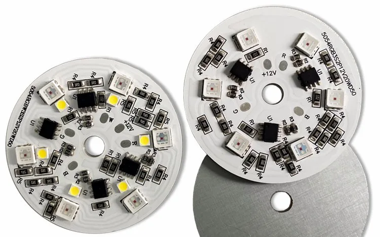
Table of Contents
- PCB อลูมิเนียมคืออะไร?
- โครงสร้าง PCB อะลูมิเนียม
- แผงวงจรพิมพ์อะลูมิเนียมเทียบกับแผงวงจรพิมพ์ FR4
- คุณสมบัติของวัสดุ PCB อะลูมิเนียม
- ประเภทของ PCB อลูมิเนียม
- กระบวนการผลิตแผ่นวงจรพิมพ์อลูมิเนียม
- การใช้งาน PCB อะลูมิเนียม
- แนวทางการออกแบบแผงวงจรพิมพ์อะลูมิเนียม
- ปัจจัยต้นทุนของแผ่นวงจรพิมพ์อะลูมิเนียม
- การผลิตและประกอบแผงวงจรพิมพ์อลูมิเนียมตามสั่ง
- คำถามที่พบบ่อยเกี่ยวกับ PCB อลูมิเนียม
- สรุป
Table of Contents
- PCB อลูมิเนียมคืออะไร?
- โครงสร้าง PCB อะลูมิเนียม
- แผงวงจรพิมพ์อะลูมิเนียมเทียบกับแผงวงจรพิมพ์ FR4
- คุณสมบัติของวัสดุ PCB อะลูมิเนียม
- ประเภทของ PCB อลูมิเนียม
- กระบวนการผลิตแผ่นวงจรพิมพ์อลูมิเนียม
- การใช้งาน PCB อะลูมิเนียม
- แนวทางการออกแบบแผงวงจรพิมพ์อะลูมิเนียม
- ปัจจัยต้นทุนของแผ่นวงจรพิมพ์อะลูมิเนียม
- การผลิตและประกอบแผงวงจรพิมพ์อลูมิเนียมตามสั่ง
- คำถามที่พบบ่อยเกี่ยวกับ PCB อลูมิเนียม
- สรุป
If you’ve ever designed a high-power LED array only to watch it dim severely after a few hundred hours, or built a motor drive that kept tripping thermal limits, you already know the core problem: heat. Standard FR-4 PCBs have thermal conductivity of roughly 0.3–0.4 W/m·K — they act more like thermal blankets than heat spreaders. An aluminum PCB (also called an aluminum core PCB, metal core PCB, or MCPCB) solves this by replacing the fiberglass substrate with an aluminum base that conducts heat 500–800 times more effectively.
This guide covers everything you need to know about aluminum PCBs: how they’re constructed, what makes them different from FR-4, which material properties matter, how they’re manufactured, where they’re used, and how to design and source them for your next project.
What Is an Aluminum PCB?
An aluminum PCB is a type of metal core printed circuit board that uses an aluminum alloy as its base substrate instead of the standard FR-4 fiberglass laminate. The aluminum base acts as a built-in heat sink, pulling heat away from power components and spreading it across the entire board surface.
Unlike standard PCBs where heat becomes trapped in the fiberglass layers, aluminum PCBs provide a direct thermal path from hot components to the metal core, dramatically reducing junction temperatures.
When to consider an aluminum PCB:
- Your design dissipates more than 1–2W per component
- Operating ambient temperatures exceed 70°C
- The product cannot accommodate active cooling (fans)
- Mechanical stability under vibration matters
- You want to eliminate separate heat sinks from the BOM
Aluminum PCB Structure
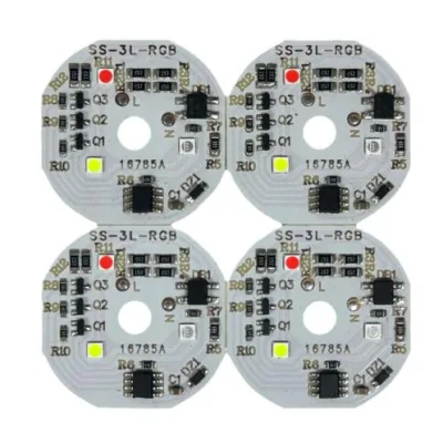
An aluminum PCB consists of three bonded layers, each serving a critical function:
| Layer | Material | Typical Thickness | Function |
| Circuit Layer | Copper foil (1oz, 2oz, 3oz) | 35–105 µm | Component mounting, signal routing, current carrying |
| Dielectric Layer | Thermally conductive insulation | 50–200 µm | Electrical isolation + heat transfer |
| Aluminum Base | 5052 or 6061 aluminum alloy | 0.8–3.0 mm | Mechanical support + lateral heat spreading |
The Dielectric Layer: The Critical Component
The dielectric layer is the most important part of an aluminum PCB. It must provide electrical isolation (typically 2–3 kV breakdown voltage) while conducting heat efficiently. This is a difficult materials challenge — most electrical insulators are also thermal insulators.
Standard dielectrics use ceramic-filled epoxy formulations that achieve 1–2 W/m·K. Premium dielectrics, using advanced ceramic fillers and optimized resin systems, can reach 3–8 W/m·K or higher.
The dielectric thickness directly affects both isolation voltage and thermal resistance:
| Dielectric Thickness | Breakdown Voltage | Thermal Conductivity Impact |
| 50 µm (thin) | ~1.5 kV | Lowest thermal resistance — best heat transfer |
| 100 µm (standard) | ~3 kV | Good balance for most applications |
| 150–200 µm (thick) | ~4–6 kV | Higher isolation, higher thermal resistance |
The Aluminum Base: Why Aluminum Specifically
Aluminum is chosen for the metal core because of its excellent combination of thermal conductivity, weight, and cost.
| Material | Thermal Conductivity (W/m·K) | Density (g/cm³) | Relative Cost | Why Used |
| Aluminum (5052) | 138 | 2.68 | Low | Best all-around balance |
| Aluminum (6061) | 167 | 2.70 | Low | Higher strength when needed |
| Copper | 398 | 8.96 | High | Best thermal performance, heavy |
| Steel | 50 | 7.85 | Low | Rarely used — poor thermal performance |
The lateral heat spreading capability of the aluminum base (138–167 W/m·K) is what makes MCPCBs effective. Heat travels rapidly across the entire board surface, increasing the effective cooling area.
Aluminum PCB vs FR4 PCB
The fundamental difference between aluminum PCBs and standard FR-4 boards comes down to thermal management capability.
| Factor | Aluminum PCB | FR4 PCB |
| Base material | Aluminum metal core | Fiberglass epoxy laminate |
| Thermal conductivity (system) | 1–3 W/m·K | 0.3–0.5 W/m·K |
| Heat dissipation | Excellent — pulls heat from components | Poor — traps heat in board |
| Mechanical strength | High — metal base resists vibration | Moderate — can crack under stress |
| Weight | Heavier (metal core) | Lighter |
| Max operating temperature | ~130–150°C (dielectric limited) | ~130–140°C (Tg limited) |
| Layer count flexibility | Limited (1–4 layers typical) | High (up to 50+ layers) |
| Fine-pitch routing | Challenging (thick copper) | Excellent |
| EMI shielding | Natural (aluminum base acts as shield) | Requires separate shielding |
| Relative cost | 1.5–3x FR4 | Baseline |
| Best fit | High-power or heat-sensitive products | Standard signal and control boards |
What This Means in Practice
An aluminum PCB can sustain power loads 4–10 times higher than an equivalently sized FR-4 board before reaching the same hotspot temperature. For a 10W LED on FR-4, you’d need a large external heat sink. On an aluminum PCB, the board itself manages the heat.
This doesn’t mean aluminum PCBs replace FR-4 everywhere. For low-power digital circuits, signal processing boards, and any design under 1–2W dissipation, FR-4 remains the more cost-effective choice.
Aluminum PCB Material Properties
Several material properties determine how well an aluminum PCB will perform in your application.
| Property | Why It Matters | Typical Values |
| Thermal conductivity | Determines how efficiently heat moves away from components | 1–3 W/m·K (system), 138–167 W/m·K (aluminum core) |
| Dielectric layer thickness | Affects insulation and heat transfer | 50–200 µm |
| Dielectric breakdown voltage | Maximum voltage before insulation fails | 2–6 kV depending on thickness |
| Copper thickness | Impacts current capacity and heat spreading | 1oz (35 µm), 2oz (70 µm), 3oz (105 µm) |
| Aluminum base thickness | Affects rigidity and thermal mass | 0.8–3.0 mm |
| Surface finish | Influences solderability and shelf life | ENIG, OSP, HASL, Immersion Silver |
| Solder mask type | Affects reliability and protection | White, Black, Green |
| CTE (Coefficient of Thermal Expansion) | Mismatch with components affects reliability | ~23–25 ppm/°C (aluminum) |
Understanding Thermal Conductivity in Aluminum PCBs
Thermal conductivity in an aluminum PCB is a system-level property, not a material-level one. The three-layer construction means the dielectric layer creates the thermal bottleneck.
The total thermal resistance is calculated as:
Rth = Thickness / (k × Area)
For a 100 µm dielectric with k = 2 W/m·K under a 10mm × 10mm component:
Rth = 0.0001 / (2 × 0.0001) = 0.5 °C/W
This is excellent. By comparison, the same calculation for FR-4 (k = 0.3 W/m·K, standard thickness) would give roughly 3–5 °C/W — 6–10 times higher.
Need PCB Manufacturing or Assembly?
Get a free quote within 24 hours. We specialize in prototype-to-production PCB/PCBA for hardware teams worldwide.
Types of Aluminum PCBs
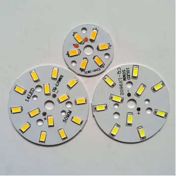
Not all aluminum PCBs are the same. The right type depends on your application’s complexity, thermal requirements, and budget.
| Type | Layer Count | Complexity | Relative Cost | Common Applications |
| Single-Layer | 1 copper layer | Low | Baseline | LED strips, simple lighting, power resistors |
| Double-Layer | 2 copper layers | Moderate | 1.5–2x | Power supplies, automotive modules, DC-DC converters |
| Multi-Layer | 4+ copper layers | High | 3–5x | Complex power distribution, telecom base stations |
| Hybrid (Al + FR4) | Mixed stackup | Very High | 4–6x | Signal + power on same board, automotive ECUs |
| Flexible Aluminum | Specialized thinning | Very High | 5–8x | Curved lighting, space-constrained designs |
Single-Layer Aluminum PCB
The most common and cost-effective type. A single copper layer is etched on top of the dielectric and aluminum base. Ideal for simple LED lighting, power resistors, and basic thermal management applications.
Double-Layer Aluminum PCB
Two copper layers allow for more complex routing while maintaining thermal performance. Useful for power supplies that need both top-side components and bottom-side traces.
Multi-Layer Aluminum PCB
Building multiple copper layers on an aluminum core is challenging because through-holes must be carefully isolated from the metal base. These boards are used in complex power distribution systems where high layer count is essential.
Hybrid Aluminum PCB
Hybrid boards combine FR-4 layers (for signal routing) with an aluminum base (for thermal management). This approach is increasingly popular in automotive power modules where control circuitry coexists with high-current drivers on a single board.
Flexible Aluminum PCB
A niche product that uses thinned aluminum cores and specialized dielectrics to achieve limited bendability. Used for curved LED arrays and applications where a rigid PCB won’t fit.
Aluminum PCB Manufacturing Process
Manufacturing aluminum PCBs requires different processes than standard FR-4 fabrication. The metal core introduces unique challenges at every step.
Step-by-Step Manufacturing Flow
| Step | Process | Key Considerations |
| 1 | Aluminum substrate preparation | Cleaning, surface treatment for dielectric adhesion |
| 2 | Dielectric lamination | Heat + pressure bonding of thermal layer to aluminum |
| 3 | Copper foil lamination | Bonding copper to dielectric under controlled conditions |
| 4 | Circuit patterning | Photoresist application, UV exposure, etching |
| 5 | Drilling | Burr prevention critical; isolation from aluminum core required |
| 6 | Solder mask application | White mask standard for LED (enhances reflectivity by 10–15%) |
| 7 | Surface finish | ENIG (preferred for SMT), OSP, or lead-free HASL |
| 8 | Electrical testing | Hip-pot testing for dielectric breakdown verification |
Key Manufacturing Challenges
Drilling: Through-holes must be electrically isolated from the aluminum core. This requires precise drilling followed by desmearing and epoxy plugging before plating. Any drill burr contacting the aluminum creates a short.
Dielectric Lamination: The dielectric layer must bond uniformly without voids. Air pockets create thermal hot spots and potential breakdown points. Lamination is done under high temperature and pressure in specialized presses.
Copper Etching: Thick copper (2oz+) requires longer etch times, which can undercut fine features. For designs requiring both heavy copper and fine-pitch traces, specialized etching processes are needed.
Surface Finishes for Aluminum PCB
| Surface Finish | Shelf Life | Flatness | Best For |
| ENIG | 12 months | Excellent | SMT, fine-pitch components, high reliability |
| OSP | 6 months | Excellent | Cost-sensitive, lead-free assembly |
| Lead-Free HASL | 12 months | Moderate | General purpose, robust solder joints |
| Immersion Silver | 6 months | Good | High-frequency, good solderability |
ENIG is the most commonly recommended surface finish for aluminum PCBs because of its excellent flatness and long shelf life. White solder mask is standard for LED applications as it improves light output by reflecting upward instead of absorbing it.
Aluminum PCB Applications
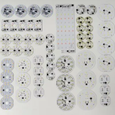
Aluminum PCBs are used wherever heat management is critical to product performance and reliability.
| Application | Why Aluminum PCB Is Used | Typical Power Range |
| LED lighting | Moves heat away from LED chips, prevents lumen degradation | 10–200W per module |
| Power supplies | Improves thermal stability of switching components | 50–500W |
| Automotive electronics | Handles heat and vibration in engine bays | 20–300W |
| Industrial controls | Supports reliable operation in harsh environments | 50–1000W |
| Audio amplifiers | Manages heat from power transistors | 30–200W |
| Battery and charging systems | Thermal management in high-current circuits | 50–500W |
| Solar inverters | Heat dissipation in outdoor enclosures | 100–2000W |
| Medical devices | Consistent thermal performance in diagnostic equipment | 10–150W |
LED Lighting (Most Common Application)
The LED lighting industry is the largest user of aluminum PCBs. An LED’s light output and lifespan are directly tied to its junction temperature. Every 10°C increase above the rated junction temperature cuts LED lifespan by roughly 50%.
Aluminum PCBs keep LED junction temperatures in the 80–100°C range even with high drive currents, enabling the bright, long-lasting LED products we rely on for street lighting, automotive headlights, grow lights, and industrial illumination.
Automotive Electronics
Automotive environments combine high ambient temperatures (under hood: 105–125°C), vibration, and tight packaging. Aluminum PCBs are used in LED headlights, DC-DC converters, battery management systems, and motor controllers.
Power Electronics
Switch-mode power supplies, motor drives, and solar inverters all generate significant heat from IGBTs, MOSFETs, and diodes. Aluminum PCBs provide the thermal path needed to keep these components within safe operating limits.
Aluminum PCB Design Guidelines
Proper design is essential to get the most out of an aluminum PCB. Here are practical guidelines that directly affect thermal and electrical performance.
1. Match Copper Thickness to Current Requirements
For 2oz copper on aluminum substrate, typical current capacity improves significantly compared to FR-4 because the aluminum base helps dissipate trace heat:
| Current (A) | Min Trace Width (2oz Copper, 20°C Rise) | Notes |
| 5A | 1.0mm | Standard routing |
| 10A | 2.5mm | Moderate power |
| 20A | 6.0mm | High current, use wide pours |
| 30A | 10.0mm | Heavy copper recommended |
| 50A | 20.0mm | Use 3oz+ copper, multiple layers |
2. Choose Dielectric Thickness Based on Voltage and Thermal Needs
Thinner dielectrics transfer heat better but provide less isolation. As a rule of thumb:
- 50 µm dielectric:Use for low-voltage (< 48V) designs where thermal performance is critical
- 100 µm dielectric:Standard for most applications up to 300V
- 150–200 µm dielectric:Required for mains voltage isolation (250V+)
3. Place High-Power Components Where Heat Can Spread Naturally
Position high-wattage components away from board edges so heat can spread in all directions through the aluminum core. Maintain at least 5–10mm clearance from board edges for power components.
4. Use Thermal Via Arrays When Needed
While the aluminum base handles most thermal spreading, thermal via arrays (0.3–0.5mm diameter, 1.0–1.5mm pitch) under hot components help pull heat from surface-mount pads into the dielectric and aluminum layers below. Via-in-pad designs maximize this effect.
5. Avoid Unnecessary Complexity
If a single-layer aluminum PCB handles your thermal requirements, don’t design a multi-layer board. Each additional layer adds cost and complexity without thermal benefit. Hybrid designs should only be specified when signal density genuinely requires them.
6. Confirm Surface Finish Based on Assembly Requirements
ENIG is the most reliable choice for SMT assembly on aluminum PCBs. OSP is a lower-cost option with adequate performance for less demanding applications. Lead-free HASL works but may have flatness issues for fine-pitch components.
7. Review Gerber Files and Stackup Before Production
Always submit your stackup specification with your Gerber files. The dielectric type, copper weight, and aluminum thickness must be clearly communicated to the fabricator. Request DFM feedback before committing to production.
Aluminum PCB Cost Factors
Aluminum PCBs typically cost more than equivalent FR-4 boards, but the premium is often offset by eliminating separate heat sinks.
| Cost Factor | Impact on Price | Notes |
| Aluminum vs FR-4 base material | +20–50% | Aluminum costs more per square meter than fiberglass |
| Dielectric type | +10–40% | Premium dielectrics (3+ W/m·K) cost significantly more than standard |
| Copper weight | +10–30% per oz increase | 2oz costs more than 1oz; 3oz more than 2oz |
| Layer count | +50–100% per additional layer | Multi-layer aluminum is significantly more expensive |
| Surface finish | +5–20% | ENIG costs more than OSP or HASL |
| Panel utilization | ± 10–20% | Standard panel sizes improve utilization and reduce waste |
| Volume | 30–50% reduction at scale | Higher quantities reduce per-unit cost substantially |
Typical Cost Comparison
| Board Type | 2-Layer FR-4 | Single-Layer Aluminum | 2-Layer Aluminum | Hybrid Al + FR4 |
| Relative cost (prototype) | 1x (baseline) | 1.5–2x | 2–3x | 3–5x |
| Relative cost (production) | 1x | 1.3–1.8x | 1.8–2.5x | 2.5–4x |
The real cost savings come from system-level BOM reduction. Replacing a $2–5 heat sink and thermal interface material with an aluminum PCB that costs $0.50–1.50 more than FR-4 often results in net savings.
Custom Aluminum PCB Fabrication and Assembly
When your project demands custom aluminum PCBs with verified thermal performance, working with an experienced manufacturer makes the difference between a design that works and one that fails in the field.
PCBAndAssembly supports custom aluminum PCB fabrication for LED lighting, power electronics, automotive, industrial control, and thermal management applications. With capability across single-layer through multi-layer hybrid designs, the engineering team provides DFM feedback within 24 hours.
Aluminum PCB FAQ
1) What is an aluminum PCB used for?
Aluminum PCBs are primarily used in applications where heat management is critical. The most common use is LED lighting (street lights, automotive headlights, grow lights, flood lights). Other major applications include power supplies, automotive electronics (ECUs, DC-DC converters, LED drivers), motor drives, solar inverters, and audio amplifiers. Any design where components generate significant heat and need efficient thermal dissipation is a candidate for aluminum PCB.
2) How does an aluminum PCB differ from a standard FR-4 board?
The fundamental difference is the substrate. Aluminum PCBs use an aluminum metal core instead of FR-4 fiberglass. This gives them 500–800 times better lateral heat spreading (aluminum: 138–167 W/m·K vs FR-4: 0.3 W/m·K). Aluminum PCBs also provide natural EMI shielding, higher mechanical strength, and better vibration resistance. However, they are heavier, more expensive, and limited in layer count compared to FR-4.
3) Can aluminum PCBs be multi-layer?
Yes, aluminum PCBs can be manufactured with multiple copper layers (2, 4, or even 6+ layers), though complexity and cost increase significantly. Multi-layer aluminum PCBs require precise drilling and isolation techniques to prevent short circuits between layers and the metal core. Hybrid boards combining FR-4 layers with an aluminum base are a popular alternative for designs needing both complex routing and thermal management.
4) Are aluminum PCBs expensive?
Aluminum PCBs typically cost 1.5 to 3 times more than equivalent FR-4 boards. The premium comes from the aluminum base material, specialized dielectric layer, and more complex manufacturing.
5) How do I choose the right dielectric for my aluminum PCB?
Choose the dielectric based on your thermal and voltage requirements. For low-voltage (< 48V), thermally demanding designs, use a thin (50 µm) premium dielectric (3+ W/m·K). For general applications up to 300V, a standard 100 µm dielectric (1–2 W/m·K) works well. For mains voltage isolation (250V+), use a thicker 150–200 µm dielectric. Higher thermal conductivity dielectrics cost more, so match the grade to your actual thermal budget.
6) What surface finish is best for aluminum PCBs?
ENIG (Electroless Nickel Immersion Gold) is the most reliable choice for aluminum PCBs, especially for SMT assembly. It offers excellent flatness, long shelf life (12 months), and good solderability for fine-pitch components. OSP is a cost-effective alternative for less demanding applications. Lead-free HASL works but may have flatness issues. Avoid immersion tin for aluminum PCBs in high-reliability applications.
7) Do aluminum PCBs support surface mount components?
Yes, aluminum PCBs fully support SMT assembly. ENIG surface finish is recommended for SMT due to its flat surface and excellent solderability. The thermal mass of the aluminum base may require slightly adjusted reflow profiles — the board absorbs heat faster than FR-4, so preheat zones may need to be extended by 10–20 seconds to ensure uniform temperature across the assembly.
8) How long does an aluminum PCB last?
The lifespan of an aluminum PCB is primarily determined by the dielectric layer and the operating environment. In well-designed applications with proper thermal management, aluminum PCBs can last 50,000–100,000+ hours. Premium dielectrics maintain their thermal performance over the product’s lifetime without degradation. The aluminum base itself does not degrade. Most failures are caused by thermal cycling fatigue in the dielectric or solder joints rather than the board itself.
Conclusion
Aluminum PCBs solve one of the most persistent challenges in power electronics: how to move heat away from components efficiently and reliably. By replacing FR-4’s insulating fiberglass with a thermally conductive metal core, aluminum PCBs reduce hotspot temperatures by 20–40°C, eliminate the need for separate heat sinks in many designs, and extend product lifespan by keeping semiconductor junctions within safe operating ranges.

Get Quote Free