
Common Problems in Flexible PCB Assembly and Design Optimization
Flexible PCB assembly often suffers from warping, solder joint stress, and thermal issues. This article explains why they happen and how smarter design choices.
Get Your PCB Quote!
Table of Contents
- 1. Einführung in flexible Leiterplatten
- 2. Die Einzigartigkeit flexibler Leiterplatten
- 3. Wichtigste Vorteile der flexiblen Leiterplattenbestückung
- 4. Materialien, die bei der Herstellung flexibler Leiterplatten verwendet werden
- 5. Der flexible Leiterplattenbestückungsprozess (Flex PCBA)
- 6. Häufige Herausforderungen in Flexible Leiterplattenbestückung
- 7. Designüberlegungen für optimale flexible Leiterplatten
- 8. Die Anwendung von Flexible Leiterplattenbestückung
- 9. Flexible Leiterplattenbestückung FAQs
- 10. Zusammenfassung
- Wichtige Erkenntnisse

1. Introduction to Flexible PCBs
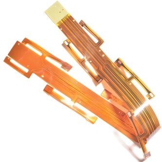
In the rapidly evolving landscape of electronics, traditional rigid printed circuit boards (PCBs) are increasingly being complemented, and sometimes replaced, by their more adaptable counterparts: flexible PCBs. A flexible PCB, often simply called a flex circuit, is a circuit board whose components are mounted on a flexible substrate, allowing the circuit to conform to various shapes and sizes, bend, and even twist without compromising electrical integrity. This unique characteristic makes flexible PCB assembly a critical process for modern, compact, and high-performance electronic devices.
The journey from a bare flexible circuit to a fully functional electronic module—the flexible PCBA—is distinct from rigid board assembly. It demands specialized techniques, careful material selection, and a deep understanding of the inherent properties of flexible substrates. This comprehensive guide will delve into the intricacies of flexible PCB assembly, exploring its processes, advantages, challenges, and diverse applications that are shaping the future of electronics.
2. The Uniqueness of Flexible Circuit Boards
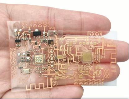
Unlike conventional rigid PCBs, which utilize materials like FR-4 that are stable and unyielding, flexible PCBs employ substrates such as polyimide (PI) or polyester (PET). These materials possess inherent flexibility, allowing circuits to bend, fold, and twist. This flexibility isn’t just a design convenience; it’s a fundamental property that enables innovative product designs that are impossible with rigid boards. The ability to integrate electronics into three-dimensional spaces, reduce package size, and create dynamic interconnections sets flexible circuits apart.
3. Key Advantages of Flexible PCB Assembly
The adoption of flex PCB assembly is driven by a multitude of benefits that address the growing demands for smaller, lighter, and more robust electronic devices:
- Space and Weight Reduction:Flexible circuits can be folded or bent into compact shapes, significantly reducing the volume and weight of electronic devices. This is crucial for portable electronics, wearables, and aerospace applications.
- Enhanced Reliability:By eliminating the need for multiple connectors, cables, and discrete wiring, flexible PCBs reduce potential points of failure, leading to higher system reliability and lower assembly costs.
- Dynamic Flexibility:Flex circuits are designed to withstand repeated bending and flexing, making them ideal for applications requiring movement, such as robotic arms, camera gimbals, and hinged devices.
- Improved Heat Dissipation:Depending on the design and materials, some flexible circuits can offer better thermal management than traditional wiring harnesses, especially when copper traces are effectively utilized as heat sinks.
- Simplified Assembly:A single flexible circuit can replace multiple rigid boards and their interconnect s, streamlining the assembly process and reducing manual labor.
- Shock and Vibration Resistance:The inherent flexibility of the substrate materials allows them to absorb shock and vibration better than rigid boards, enhancing durability in harsh environments.
4. Materials Used in Flexible PCB Manufacturing
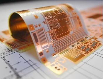
The choice of materials is paramount in flex PCB manufacturing, directly impacting the circuit’s performance, durability, and flexibility. Here are the primary components:
| Component | Common Material | Key Property/Role |
| Base Film (Substrate) | Polyimide (PI), Polyester (PET) | Provides mechanical support and dielectric insulation; dictates flexibility and temperature resistance. |
| Conductor | Rolled Annealed Copper, Electrodeposited Copper | Forms the electrical traces; chosen for conductivity and flexibility (rolled annealed is superior for flexing). |
| Adhesive | Acrylic, Epoxy, Pressure Sensitive Adhesives | Bonds the conductor to the base film and the coverlay to the traces; must be flexible and withstand process temperatures. |
| Coverlay/Solder Mask | Polyimide (PI) with adhesive, Liquid Photoimageable Solder Mask (LPSM) | Protects the circuit traces from environmental factors, contaminants, and physical damage; provides insulation and defines solderable areas. |
| Stiffener | FR-4, Polyimide, Aluminum | Added to specific areas to provide mechanical support for connectors or components, preventing stress and maintaining flatness during assembly. |
5. The Flexible PCB Assembly Process (Flex PCBA)
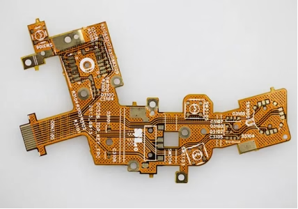
The process of assembling a flexible circuit board, or Flex PCB, shares similarities with rigid PCB assembly but requires specific adaptations due to the delicate and non-rigid nature of the substrate. The goal is to attach electronic components (like integrated circuits, resistors, capacitors, and connectors) to the flexible substrate, creating an assembled flexible PCB.
5.1 Preparation and Material Handling
Before assembly, flexible PCBs often require special preparation. They are typically supplied in panels, sometimes with a rigid frame (rigid-flex PCBs) or attached to a carrier board to facilitate handling by automated equipment. Cleaning is crucial to remove any contaminants that could interfere with solder adhesion.
5.2 Solder Paste Application
This is a critical step, especially for flex PCB SMT assembly. Solder paste is applied to component pads using a stencil. Due to the inherent flexibility of the substrate, precision is key. Special stencils with thinner apertures or more precise alignment mechanisms may be used to ensure consistent paste deposition without damaging the delicate flex material. The non-planar nature can make uniform paste deposition challenging.
5. 3 Component Placement
Automated pick-and-place machines are used to precisely position surface-mount components onto the solder paste. Fiducial markers on the flex panel guide the machine. Care must be taken to prevent excessive pressure during placement, which could damage the flexible substrate or displace components.
5.4 Reflow Soldering
After component placement, the assembled flexible circuit board undergoes reflow soldering. This process melts the solder paste, forming reliable electrical and mechanical connections between components and the flex circuit. Temperature profiles must be carefully managed to prevent thermal shock or warping of the flexible substrate. Overheating can damage polyimide or adhesives. Some flex materials require lower peak temperatures and slower ramp rates compared to rigid boards.
5.5 Inspection and Testing
Thorough inspection and testing are essential for ensuring the quality and functionality of the assembled flexible PCB. This includes:
- Automated Optical Inspection (AOI):Checks for solder joint quality, component presence, polarity, and alignment.
- X-ray Inspection:Used for components with hidden solder joints (e.g., BGAs, QFNs) to detect voids or shorts.
- Electrical Testing:Functional testing and in-circuit testing ( ICT) verify the electrical performance and ensure all circuits are working as designed. Special fixtures may be needed for flexible circuits to maintain their shape during testing.
5.6 Conformal Coating (Optional)
For applications requiring extra protection against moisture, dust, chemicals, or extreme temperatures, a conformal coating may be applied to the assembled flexible PCB. This thin, protective layer conforms to the shape of the components and the circuit.
5.7 Depanelization/Singulation
Finally, individual flexible circuits are separated from the larger assembly panel. This can be done through methods like laser cutting, routing, or specialized punching, depending on the design and material.
6. Common Challenges in Flexible PCB Assembly
While the benefits of flex PCB assembly are numerous, the process comes with its own set of challenges that require specialized expertise:
- Handling and Alignment:The non-rigid nature of flexible substrates makes them prone to warping, stretching, and misalignment during automated processes, particularly solder paste printing and component placement. Specialized fixtures and carriers are often necessary.
- Thermal Management:Flexible materials typically have lower thermal mass and different thermal expansion coefficients than rigid boards. Managing heat during reflow soldering is critical to prevent damage, delamination, or warpage.
- Solder Joint Reliability:Achieving consistent and robust solder joints on flexible substrates can be more difficult. The flexibility of the board itself can introduce stress on solder joints, especially in areas that experience frequent bending.
- Component Stress:Heavy or stiff components mounted on a flexible circuit can introduce localized stress points, potentially leading to delamination or cracking if not properly designed and supported.
- Material Compatibility:Ensuring compatibility between the flexible substrate, adhesives, solder paste, and components is crucial for long-term reliability.
7. Design Considerations for Optimal Flex PCBA
Successful flexible PCB assembly begins with thoughtful design. Addressing potential challenges at the design stage can significantly improve yield and reliability.
- Bend Radius:Ad here to recommended minimum bend radii to prevent conductor damage. Components should be placed away from bend areas.
- Stiffeners:Utilize stiffeners (e.g., FR-4, polyimide) in areas where components are mounted , or connectors are attached, to provide mechanical support and relieve stress.
- Via Design:Teardrop pads for vias and component pads can help improve stress distribution at the copper-to-pad interface, enhancing durability .
- Component Selection:Choose lightweight and small components whenever possible. Avoid placing large or heavy components on highly flexible areas.
- Panelization:Design the flexible circuit in a panelized format that can be easily handled by standard SMT equipment. This often involves using a rigid carrier or a rigid-flex combination.
- Thermal Relief:Implement thermal relief pads for through-hole components to prevent heat sinking during soldering and ensure proper solder joint formation.
8. The Application of Flexible PCB Assembly
The versatility and performance advantages of flexible PCBs have led to their widespread adoption across diverse industries:
- Consumer Electronics:Smartphones, tablets, cameras, laptops, smartwatches, and fitness trackers extensively use flexible circuits for compact packaging, hinged designs, and connectivity.
- Medical Devices:Implants, diagnostic equipment, hearing aids, wearable health monitors, and surgical instruments benefit from the miniature size, biocompatibility, and flexibility of these circuits.
- Automotive Industry:Advanced Driver-Assistance Systems (ADAS), LED lighting, infotainment systems, engine controls, and sensor arrays utilize flex circuits for their reliability in high-vibration environments and space-saving properties.
- Aerospace and Defense:Satellites, aircraft avionics, missile systems, and unmanned aerial vehicles (UAVs) rely on flexible PCBs for weight reduction, improved reliability, and resistance to extreme conditions.
- Industrial Equipment:Robotics, industrial sensors, barcode scanners, and test equipment leverage flexible circuits for dynamic movement and ruggedness.
- LED Lighting:Flexible LED strips and arrays allow for creative lighting designs and efficient heat management in various applications.
9. Flexible PCB Assembly FAQs
Answer: Flexible substrates are non-rigid and prone to warping or stretching, making it difficult to achieve consistent and uniform solder paste deposition with a stencil. Special fixtures and precise control over printing parameters are essential.
Yes, but with careful design. Heavy or stiff components should be placed on areas reinforced with stiffeners to provide mechanical support and distribute stress, preventing delamination or damage to the flexible substrate.
The most common base film materials are Polyimide (PI) due to its excellent thermal stability and mechanical properties, and Polyester (PET) for less demanding, lower-cost applications.
Flex PCBA stands for Flexible Printed Circuit Board Assembly. It refers to the entire process of mounting electronic components onto a flexible circuit board, including solder paste application, component placement, reflow soldering, inspection, and testing.
10. Summary
Flexible PCB assembly is a sophisticated process that underpins the development of cutting-edge electronic devices. From the selection of pliable polyimide substrates to the meticulous execution of solder paste application, component placement, and reflow soldering, every step demands precision and expertise. While presenting unique challenges related to material handling and thermal management, the unparalleled advantages of flexible circuits—including significant space and weight savings, enhanced reliability, and dynamic bending capabilities—make them indispensable across a wide array of applications.
Key Takeaways
- Flexible PCBs enable compact, lightweight, and dynamically bendable electronic designs, crucial for modern devices.
- The flex PCB assembly process requires specialized techniques for handling non-rigid substrates, precise solder paste application, and careful thermal management during reflow.
- Key materials include polyimide (PI) for the base film, rolled annealed copper for conductors, and flexible adhesives and coverlays.
- Challenges like warping, precise alignment, and thermal stress during soldering are overcome through careful design and specialized equipment.
- Strategic design considerations, such as proper bend radii, stiffeners, and via design, are critical for reliable flexible PCBA.
- Flexible circuits are vital in consumer electronics, medical devices, automotive, and aerospace industries, demonstrating their broad utility.
Table of Contents
- 1. Einführung in flexible Leiterplatten
- 2. Die Einzigartigkeit flexibler Leiterplatten
- 3. Wichtigste Vorteile der flexiblen Leiterplattenbestückung
- 4. Materialien, die bei der Herstellung flexibler Leiterplatten verwendet werden
- 5. Der flexible Leiterplattenbestückungsprozess (Flex PCBA)
- 6. Häufige Herausforderungen in Flexible Leiterplattenbestückung
- 7. Designüberlegungen für optimale flexible Leiterplatten
- 8. Die Anwendung von Flexible Leiterplattenbestückung
- 9. Flexible Leiterplattenbestückung FAQs
- 10. Zusammenfassung
- Wichtige Erkenntnisse

Get Your PCB Quote!


