
How to Test a Assembled Printed Circuit Board?
Get Your PCB Quote!
Table of Contents

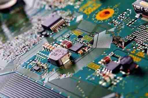
Assembled Printed Circuit Board Testing has been more difficult because of the increasing density of printed circuit boards, faster bus speeds, and analog RF devices. Functional testing in this environment requires careful design, well-thought-out test methods, and appropriate tools to provide reliable test results.
1. Importance of Assembled PCB Inspection
Assembled PCB testing is used primarily to mitigate issues during the PCBA manufacturing process, and even into final production. These tests should be run on prototypes or small assemblies in order to detect any possible flaws that could arise in the final product.
Enhance product quality: Through testing, defects can be discovered and resolved promptly, increasing product qualification rates.
Protect User Safety: An inspection helps ensure the safety of products during use and reduces risks like electrical accidents or fires.
Improve user experience: Products that have undergone rigorous testing tend to be loved by their end users more quickly.
Reduce Environmental Pollution: ROHS testing can help reduce environmental pollution by decreasing the use of toxic materials, improving green competitiveness, and encouraging environmental protection.
Ensure circuit performance: Good wiring skills can improve the performance and reliability of circuit boards, and it is necessary to detect defects in the wiring paths of circuit boards.
Circuit board inspection is an important means to ensure product quality, user safety, environmental protection, and circuit performance.
2. How to Quickly Detect Assembled Printed Circuit Board Faults?
Check the Status of the Components
When inspecting a malfunctioning circuit board, first take note of whether any obvious damage to its components exists, such as burned and swollen electrolytic capacitors, damaged resistors, and power devices that have become deformed over time.
Check Soldering on the Circuit Board
Check, for example, whether the printed circuit board is warped or deformed; whether any solder joints are detachable or there are obvious cold soldering joints; and whether the copper coating of the circuit is lifted or blackened.
Observe Component Plugin
Check if the circuit board, integrated circuit, power transformer, or diode is inserted in the wrong direction. The wrong way around.
A Simple Test of Resistors, Capacitors and Inductors
Perform simple tests with a multimeter on suspect components, such as inductors and capacitors. Check for phenomena like resistance increases, short circuits, open circuits, capacitance changes, inductor open circuits, and short circuits within the range of your multimeter.
Power-on Test
If the fault is not eliminated by the simple test and observation described above, the power-on test may be conducted. Check first that the power supply is functioning normally. Test, for example, if the AC power supply on the circuit board is not normal, if the output of the voltage regulator is not normal, a waveform or output is not normal, etc.
Flash the Program
You can flash the program again for programmable components like MCU, DSP, and CPLD to eliminate circuit faults that are caused by abnormal program operations.
Repair Based on Functional Modules
You can repair the circuit board if it cannot be repaired using the steps above. If you are unable to fix the board, you will need to identify the circuit module with the problem based on its circuit fault. Then proceed to perform the repairs according to the design drawings.
3. Assembled Printed Circuit Boards Testing Process
The Test Procedure for Bare Circuit Board Welding:
1) After receiving the circuit, check whether the circuit board is damaged, as well as whether the pad is damaged;
2) Use a Multimeter to check for a short between the power source and the ground or between power sources;
3) Weld first the part of the power supply and then debug the power source;
4) Weld the crystal oscillator, and reset the circuit and CPU resistors. After welding, retest the power supply and ground to avoid short circuits and thermal breakdown during welding. Test after welding the CPU: It is necessary to confirm that the crystal oscillator can start and reset normally. The program can be downloaded and simulated. When debugging, ensure that the corresponding IO port can be set. The IO port can be directly set to light up the LED.
5) Weld SDRAM and debug;
6) Weld the serial port and connect it to the computer for serial port input and output debugging;
7) Weld other peripheral devices and perform corresponding hardware debugging in combination with the software.
Testing Process of the Board after Welding:
√ Testing before power-on:
When checking if a circuit is working normally after welding, the board is not usually powered up directly. Instead, the steps below should be followed to make sure that the board is functioning properly at each stage.
1) Check if the connection is correct: Verify that the board connections are correct by the schematic diagram and then check each one individually according to the circuit diagram;
2) Check that the components are correctly installed: the diode and polarity capacitor, as well as the chip. Check that the device’s welding is not hot;
3) Check if the power interface is short-circuited: Check if there is a circuit short between the power source and each level. Circuits should include protection circuits, such as automatic recovery fuse. The power supply part can be designed with 0 Ω resistance, and other circuits should not be welded before powering on to test the power supply, to avoid abnormal levels burning the chip of the subsequent unit.
√ Detection after power-on:
After power-on, check according to the following steps.
1) Power-on inspection: Do not rush to measure electrical indicators after power-on. Instead, observe if the circuit exhibits any abnormal phenomenon, such as smoke or an abnormal smell. Test the temperature of an integrated circuit’s outer package by touching it. If you notice an abnormality, turn off the power immediately and then restart the power after the problem is fixed.
2) Static test: Check if the level state is as expected and restore welding resistance 0 O gradually. Debugging the sub-circuits is usually done in the direction of signal flow. The output signal from the previous level is then used as the input for the next to create the conditions for final unified adjustments.
3) Dynamic test: Add external input and out put signals gradually to debug different parts of the system. This step involves software and hardware debugging.
4. PCBA Inspection Precautions
What are the most important factors to consider when testing an Assembled PCB circuit board?
1) Use of instruments with grounded shells for testing TV, audio, and video equipment directly without isolation transformers is prohibited.
If you encounter TV or audio equipment that has a large power output or if the nature of the supply is unclear, it is important to check if the chassis is energized. Otherwise, it is easy to cause an integrated circuit to be damaged, which can lead to a short circuit.
2) As you test the printed circuit boards for insulation, pay close attention to the properties of the soldering Iron.
The soldering iron cannot be used to solder electrically. Be sure the soldering isn’t charged. The shell of the soldering tool should be ground.
3) Before you test, it is important to understand the working principles of an integrated circuit.
Understand the circuits that are made up of peripheral components, including the voltage, waveform, and functions of each pin.
4) Avoid short circuits by avoiding pins.
It is best to use an oscilloscope probe to test the waveform or measure the voltage on the peripheral printed circuit directly connected to pins. A momentary short can damage an integrated circuit.
5) Test instrument internal resistance should be high.
Select a multimeter whose head internal resistance is greater than 20KO/V when measuring the DC voltage on the pin of an integrated circuit.
6) Attention to heat dissipation.
It is forbidden to operate the power-integrated in a state of high power without a heat sink.
7) PCB board leads must be reasonable.
To avoid parasitic coupling between the preamplifier and audio power amplifier circuit, the wiring should be done with care.
8) To guarantee the quality of welding.
It is important to check the welded integrated circuit. Check for a short by using an ohmmeter prior to turning on the power.
9) It is difficult to determine the extent of damage caused to an integrated circuit.
Since most integrated circuits have a direct coupling, if a circuit becomes abnormal, multiple voltage changes may occur. These changes are not always caused by damage to an integrated circuit.
5. Summary
Printed Circuit board (PCB) is used in various electronic devices, including mobile phones, computers, and complex machines. If any defects or manufacturing problems arise in their creation, these may lead to failure and inconvenience in their final product. In such cases, manufacturers must recall the devices and spend additional time and resources repairing them. Circuit board testing has become an integral part of circuit board production. It detects problems in time, assists staff to quickly deal with them, and ensures the high quality of PCB.
Table of Contents

Get Your PCB Quote!


