What Is FR-2 PCB? When to Use It and When Not To
FR-2 PCB can cut board costs by up to 40%—or haunt your warranty department. We breaks down the thermal limits, PTH pitfalls, and design rules that determine when phenolic paper laminates earn their place and when they don't.
Get Your PCB Quote!
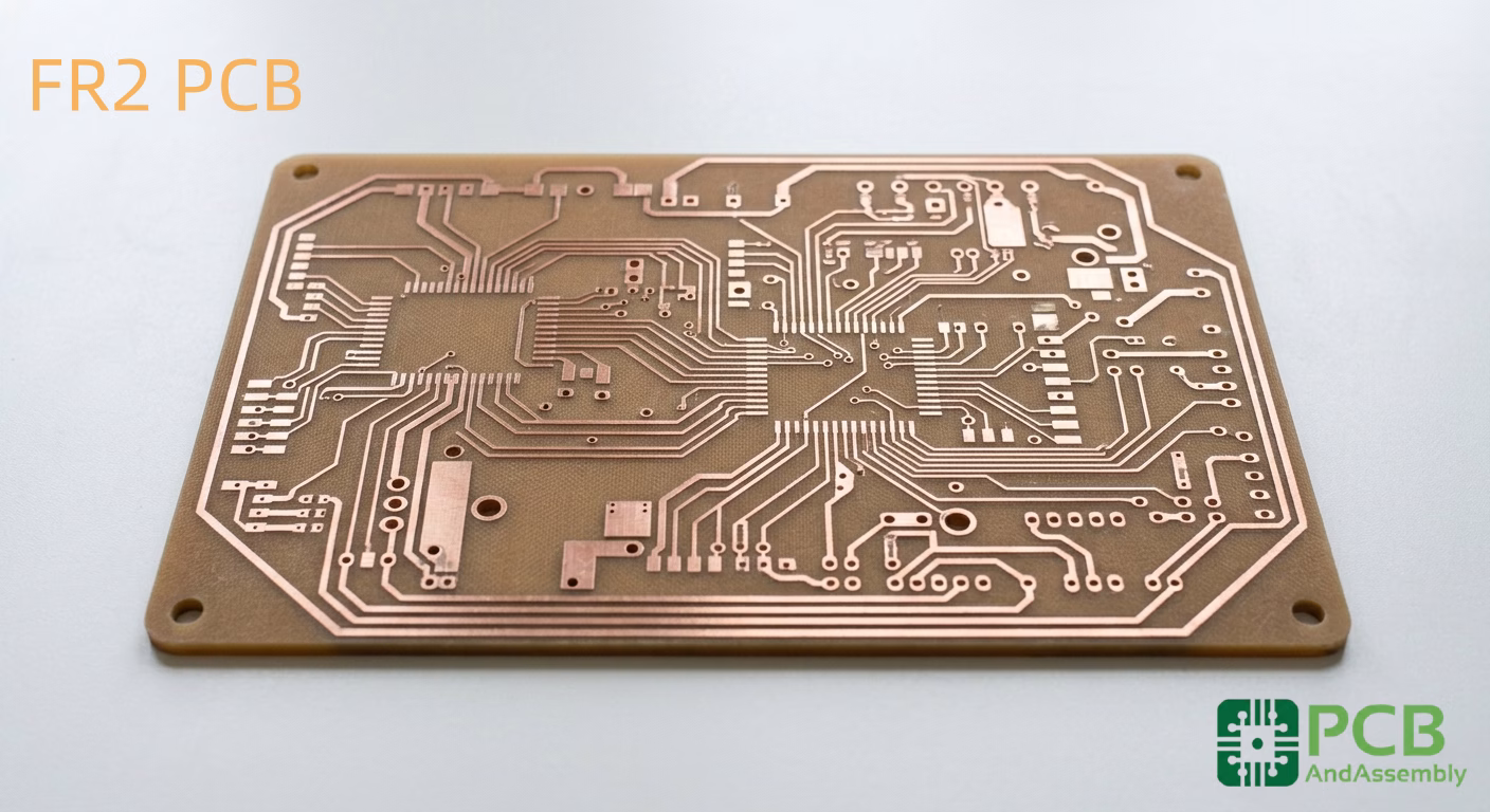
Table of Contents
- 1. Qu'est-ce que FR-2 ?
- 2. Composition des matériaux et son importance
- 3. Spécifications techniques : FR-2 vs. Le monde
- 4. La règle du « pas de placage » : pourquoi le PTH est à proscrire
- 5. Nuances de fabrication : poinçonnage vs perçage
- 6. Avis d'expert : Le piège à humidité et à chaleur
- 7. Quand choisir le FR-2 (Critères de sélection)
- QFP
- Résumé
- Références
Every year, we see a recurring scenario: a procurement manager for a high-volume consumer electronics firm looks at the bill of materials for a new power strip or a basic LED driver and asks, “Can we shave another five cents off the board cost by moving from FR-4 to FR-2?” It’s a tempting proposition when you’re projecting a run of one million units. But at PCBAndAssembly, we’ve learned that those five cents saved in the bill of materials often reappear as thousands of dollars in field returns if the environment isn’t perfectly controlled.
FR-2 isn’t a “bad” material; it’s a specific material for a specific set of constraints. If you treat it like a cheaper version of FR-4, your design will fail. If you treat it as a unique substrate with its own mechanical and thermal rules, it remains one of the most cost-effective solutions in the industry. This guide breaks down the reality of working with phenolic paper-based laminates from the perspective of the factory floor and the engineering desk.
1. What Is FR-2?
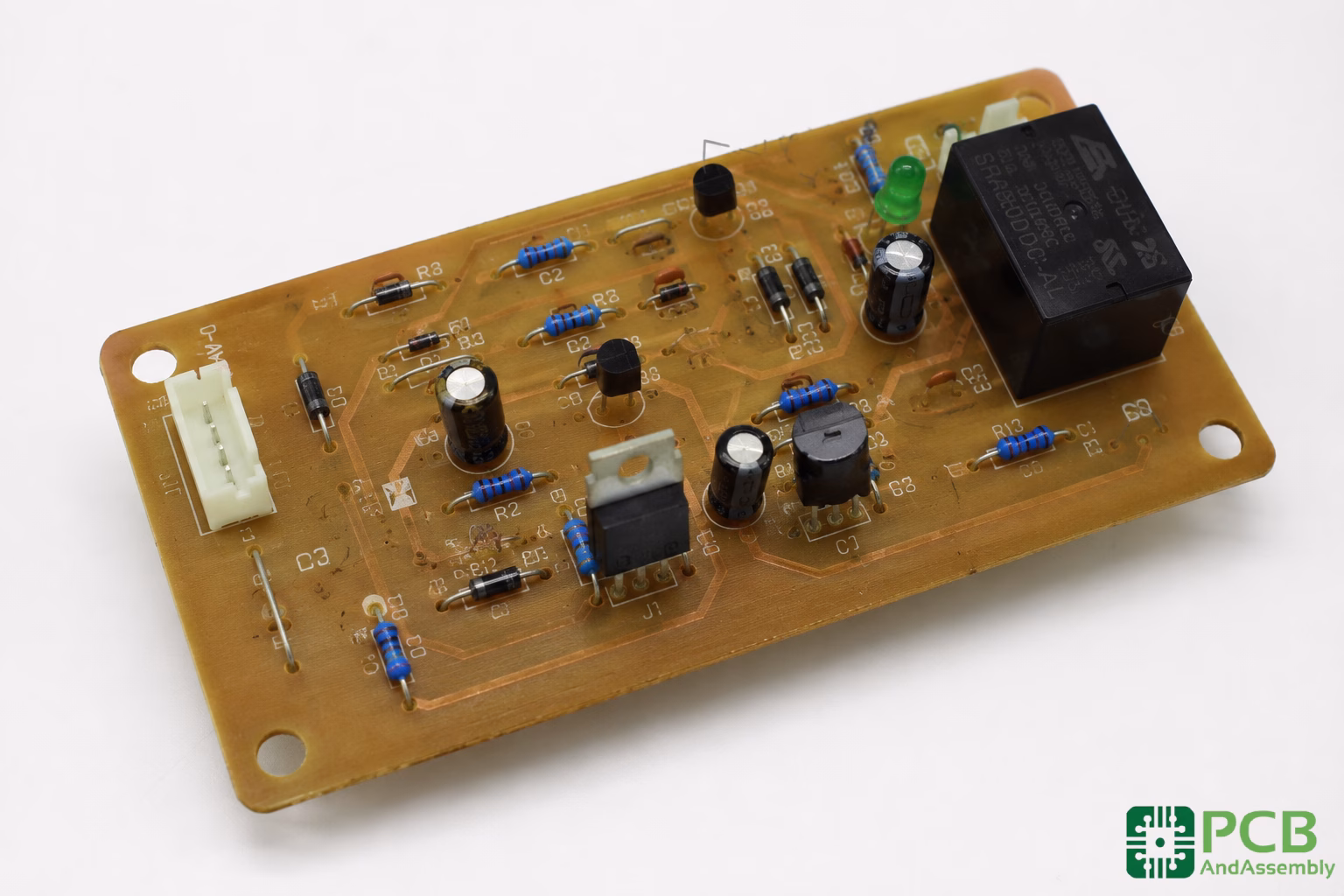
FR-2 stands for Flame Retardant 2—a NEMA designation for synthetic resin bonded paper used in printed circuit board manufacturing. It belongs to a family of “paper” PCBs that includes FR-1, FR-3, and the hybrid CEM-1. While the industry has largely consolidated around FR-4 (glass-reinforced epoxy) for anything with a microcontroller or a high-speed signal, FR-2 continues to dominate the low-end consumer market: think TV remote controls, simple battery chargers, and budget-grade power supplies.
The material’s history stretches back to the 1950s and 1960s, when it emerged as a workhorse PCB substrate for industrial controls and early instrumentation. The core composition hasn’t changed much since: cellulose or cotton paper fibers are impregnated with plasticized phenol formaldehyde resin—a thermosetting plastic that is cheaper than the epoxy used in FR-4, but also significantly more brittle. When you see an FR-2 PCB, you’re looking at a brownish board that’s noticeably different in color from the green glass-epoxy appearance of FR-4.
The “2” in FR-2 indicates its place in the IPC hierarchy. While FR-1 and FR-2 are both phenolic paper materials, FR-2 uses a slightly different resin chemistry that offers a marginal improvement in moisture resistance over FR-1. In practical manufacturing, however, the two are often used interchangeably depending on a given laminate supplier’s stock.
At PCBAndAssembly, we categorize FR-2 as a “commodity substrate.” It is designed for single-sided circuits where components are mounted via through-hole technology (THT) but without the benefit of plated-through holes (PTH). If your design requires traces on both sides or any form of via, you have already moved beyond what FR-2 can reliably deliver. One important compliance note: FR-2 meets the UL94V-0 standard—the benchmark for plastic flammability in electronics—making it a legitimate choice for consumer products with safety certification requirements.
2. Material Composition and Why It Matters
Understanding the chemistry of FR-2 explains its behavior under stress. Unlike FR-4, which uses woven fiberglass cloth, FR-2 uses cellulose paper (essentially high-grade cotton paper) as the reinforcement. This paper is impregnated with a phenolic resin that falls into two categories: resoles and novolacs. Both work effectively for PCB applications, offering reasonable adhesion to copper foil.
Phenolic resins are thermosetting plastics. They are cheaper than the epoxy resins used in FR-4 but considerably more brittle. When we process FR-2 boards, we have to account for this brittleness. If you try to snap a panel of FR-2, it doesn’t flex and craze like FR-4; it cracks cleanly or shatters if the resin content is too high. This has significant implications for mechanical mounting and vibration resistance.
Copper foil is laminated onto one or both sides of the substrate—typically at 35 µm (1 oz/ft²) standard weight, with 50 µm available for higher-current applications. That copper layer can be etched or milled to create the circuit traces your design requires. The paper base also makes FR-2 roughly 15% lighter than glass-reinforced alternatives at equivalent thicknesses, which can matter in weight-sensitive applications.
The cellulose paper reinforcement is also hygroscopic—it readily absorbs water. Even with the phenolic coating, the edges of an FR-2 board are vulnerable. We have seen cases where boards stored in high-humidity warehouses for six months showed a measurable drop in insulation resistance between high-voltage traces, leading to arcing and failure in power supply applications. Moisture absorption in FR-2 can reach 0.4%–0.8%, compared to less than 0.1% for FR-4.
3. Technical Specifications: FR-2 vs. The World
To make an informed decision, you need to look at the numbers. The table below compares FR-2 against its common competitors. Note the significant gaps in Glass Transition Temperature (Tg), moisture absorption, and mechanical strength—each with real consequences on the factory floor and in the field.
| Property | FR-2 (Phenolic Paper) | CEM-1 (Composite) | FR-4 (Glass Epoxy) |
| Base Material | Cotton Paper / Phenolic | Paper Core / Glass Surface | Woven Glass / Epoxy |
| Glass Transition (Tg) | 105°C–110°C | 110°C–120°C | 130°C–180°C |
| Moisture Absorption | ~0.4%–0.8% | ~0.2%–0.3% | <0.1% |
| Dielectric Constant (Dk) | 4.0–4.5 | 4.2–4.6 | 4.2–4.8 |
| Flexural Strength | Low (Brittle) | Moderate | High (Durable) |
| Layer Support | Single-sided primarily | Single/limited double | Up to 32+ layers |
| PTH Support | Not recommended | Limited | Excellent |
| Relative Cost | ~60% of FR-4 | ~70%–80% of FR-4 | Baseline |
| Flame Retardancy | UL 94 V-0 | UL 94 V-0 | UL 94 V-0 |
From this data, a critical professional observation emerges: FR-2 is a thermal bottleneck. Because the Tg sits at only around 105°C, the material begins to lose structural integrity at temperatures that high-power components or lead-free reflow profiles frequently approach. FR-2’s dielectric constant of around 4.5 is also on the higher end, and its dissipation factor (0.024–0.026) causes greater signal loss at elevated frequencies—making it effectively unusable above 30 MHz. For RF or high-speed digital circuits, impedance control on FR-2 is virtually non-existent.
For a deeper look at the individual FR-2 property values, the following table captures the key electrical and thermal parameters you’ll need when specifying laminate:
| Property | FR-2 Value | Notes |
| Dielectric Constant (Dk) | 4.5 (typical) | Higher than FR-4; limits high-frequency use |
| Dissipation Factor | 0.024–0.026 | Signal loss factor |
| Dielectric Strength | ~29 kV/mm | Good insulation for low-voltage applications |
| Glass Transition Temp (Tg) | 105°C–110°C | Lower than FR-4; key thermal bottleneck |
| Thermal Conductivity | ~0.25 W/m·K | Limited heat spreading; plan external thermal management |
| Standard Thickness | 1.2 mm or 1.6 mm | Thinner boards prone to warpage |
| Copper Weight | 35 µm (standard) | 50 µm available for higher current |
| Flammability Rating | UL94 HB / V-0 | V-0 rated grades available on request |
Need PCB Manufacturing or Assembly?
Get a free quote within 24 hours. We specialize in prototype-to-production PCB/PCBA for hardware teams worldwide.
4. The “No Plating” Rule: Why PTH Is a Non-Starter
One of the most common questions we get from junior designers is whether they can use FR-2 for a double-sided board with through-hole plating. The answer is a firm no.
The reason isn’t just about cost; it’s about the chemistry of the hole wall. In FR-4, the woven glass provides a stable surface that can be desmeared and activated for electroless copper plating. The cellulose paper in FR-2, however, tends to wick the plating chemicals. If you attempt to plate a hole in an FR-2 board, the chemicals soak into the paper fibers like a sponge. This leads to two catastrophic failure modes:
- Conductive Anodic Filament (CAF) Growth: The trapped chemicals create a pathway for copper filaments to grow inside the board, eventually shorting out the traces.
- Blow-outs during Soldering: Any moisture or chemicals trapped in the paper fibers will vaporize during wave soldering, causing the plating to explode out of the hole—a phenomenon known as outgassing.
PCBAndAssembly always recommends sticking to single-sided designs for FR-2. If you absolutely need a second layer of routing, the standard industry practice is to use jumper wires or move up to CEM-1, which has a glass cloth surface that allows for more reliable—though still limited—plating compared to pure paper grades. Per IEC 60335-1, maintaining a 2.5 mm creepage and clearance is required for 250V basic insulation, and this becomes especially important when you lack the via infrastructure to manage signal separation on a multi-layer board.
5. Manufacturing Nuances: Punching vs. Drilling
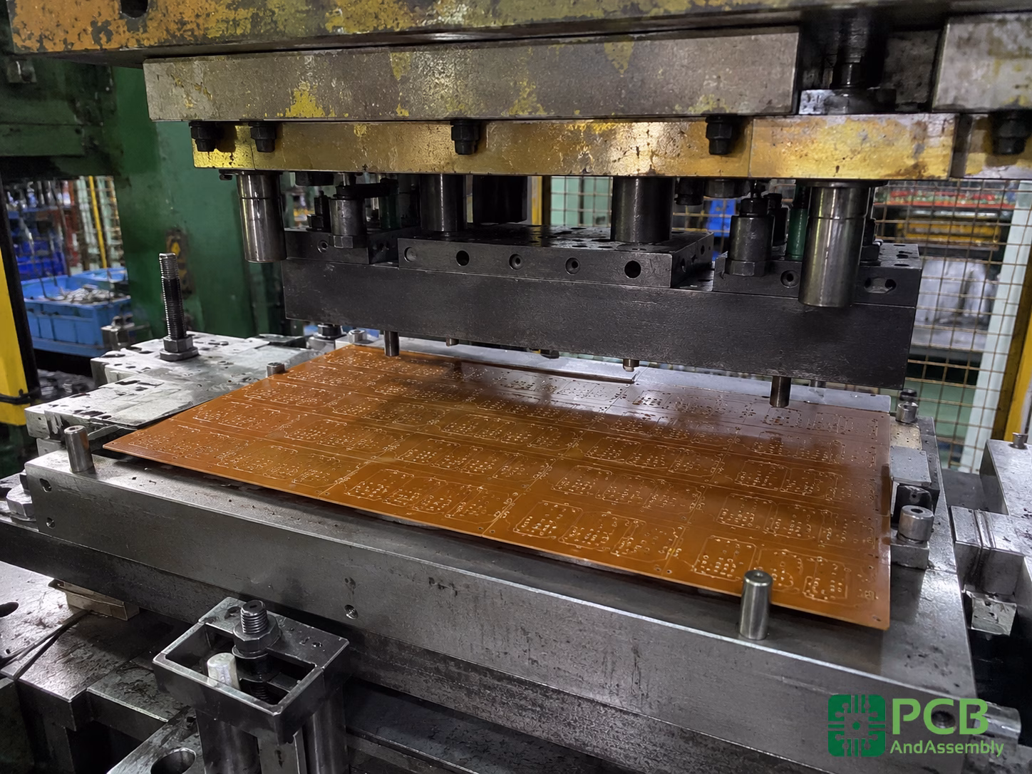
In the world of FR-4, we drill holes using high-speed CNC machines. In the high-volume world of FR-2, we often punch them. This is where the real cost savings happen—but it’s also where many designs go off the rails.
The Punching Tradeoff
Punching involves a massive die set that hits the entire board at once, creating all the holes and the board outline in a single stroke. It is incredibly fast and dramatically reduces per-piece costs in high-volume production. Unlike FR-4, which requires CNC routing for complex outlines, FR-2 can be cut with steel-rule dies—a key reason it remains viable for disposable consumer electronics despite its technical limitations.
However, punching puts immense mechanical stress on the phenolic resin. If the die isn’t sharp or the board isn’t heated correctly during the punch process (FR-2 often needs to be warmed to make the resin slightly more ductile), you get haloing or cracking around the holes.
Practitioner Insight: When designing for punched FR-2, your annular ring requirements must be much more generous than for drilled FR-4. Anything smaller than 0.5 mm risks the pad delaminating or the hole wall crumbling during the punch cycle, leading to poor solder joints later on. Use 4-spoke thermal relief patterns with spoke widths of at least 0.30 mm to prevent cold solder joints. The table below captures the full set of recommended design rules for punched FR-2 boards:
| Feature | Standard (FR-4 Drilled) | Recommended (FR-2 Punched) |
| Min Hole Diameter | 0.2 mm | 0.8 mm |
| Min Annular Ring | 0.15 mm | 0.5 mm |
| Edge-to-Trace Clearance | 0.2 mm | 0.8 mm – 1.0 mm |
| Min Trace Width | 0.1 mm | 0.25 mm |
The punching advantage does come with a surface finish consideration. HASL (Hot Air Solder Leveling) is the most common finish applied to FR-2 boards—it is cost-effective and compatible with the wave soldering process that FR-2 is designed for.
6. Professional Judgment: The Moisture and Heat Trap
If you are working on a product that will be used in tropical climates or near any heat-generating equipment, stay away from FR-2. We have seen high-volume consumer products fail in high-humidity regions because the FR-2 substrate expanded at a different rate than the copper traces, leading to trace lifting. FR-2’s thermal conductivity of roughly 0.25 W/m·K limits heat spreading significantly—for components like TO-220 packages that generate substantial heat, you’ll need to add thick copper jumpers or external aluminum heat slugs. The board itself simply won’t dissipate heat effectively.
A practical thermal rule: for traces carrying more than 2A, add 2 mm of width per amp. Placing high-power components near board edges, where heat can more readily dissipate into the surrounding air, also helps.
The Hand-Soldering Risk
While FR-2 is usually wave-soldered in mass production, rework is often done by hand. This is where many boards are ruined. Phenolic resin has very poor peel strength compared to epoxy. If a technician holds a soldering iron on an FR-2 pad for more than 3–4 seconds, the adhesive bond between the copper and the paper substrate will fail. The pad will literally lift off the board.
At PCBAndAssembly, we advise clients that if their product requires field repairability or significant manual assembly, the “savings” of FR-2 are a myth. The cost of scrapped boards during assembly and rework usually exceeds the initial material savings. FR-2 is a “one-and-done” material: it should be wave-soldered once, under a controlled profile under 245°C, and never touched again. Heavy BGAs or large SMT components should be avoided entirely—the paper substrate will delaminate or blister under excessive thermal stress.
Thermal Expansion and Warpage
We’ve observed that FR-2 panels are prone to significant warpage if the copper distribution is unbalanced. Because the paper base is less rigid than glass, a large ground plane on one side with no copper on the other will cause the board to curl during wave soldering. We recommend using copper thieving (adding non-functional copper dots) to balance the density across the panel, even on single-sided boards.
Square pads—rather than round ones—can also help resist peel-off during thermal cycling. And for designs where 250V insulation is required, maintaining 2.5 mm creepage and clearance distances per IEC 60335-1 is non-negotiable.
About PCBAndAssembly
Time is money in your projects – and PCBAndAssembly gets it. PCBAndAssembly is a PCB assembly company that delivers fast, flawless results every time. Our comprehensive PCB assembly services include expert engineering support at every step, ensuring top quality in every board. As a leading PCB assembly manufacturer, we provide a one-stop solution that streamlines your supply chain. Partner with our advanced PCB prototype factory for quick turnarounds and superior results you can trust.
7. When to Choose FR-2 (Selection Criteria)
Despite the warnings, FR-2 remains a viable choice for specific scenarios. PCBAndAssembly typically recommends FR-2 when a project meets all of the following criteria:
- Single-Sided Complexity: The circuit is simple enough to be routed on a single layer without the need for vias.
- Cost Sensitivity: The production volume is high enough—typically 50,000+ units—that per-board savings of $0.05–$0.10 significantly impact the bottom line.
- Low Power/Low Heat: The components do not generate significant localized heat, and the ambient operating temperature remains below 60°C.
- Stable Environment: The final product is intended for indoor use in temperature-controlled environments (e.g., a clock radio, a remote control).
- Mechanical Mounting: The board is supported by the plastic enclosure in a way that minimizes vibration and mechanical stress on the brittle substrate.
- Frequency: All signals remain below 30 MHz. Above that threshold, the Dk instability of paper-based laminates makes impedance control essentially impossible.
Typical applications that meet these criteria include remote controls and TV controllers, basic calculators and digital clocks, LED lighting fixtures, simple power supplies and battery chargers, and low-cost household appliances. FR-2 is also a reasonable choice for educational prototyping: it is easy to solder, affordable enough for experiments, and forgiving of beginner mistakes.
Advantages and Limitations at a Glance
| Advantage | Benefit |
| Low Cost | ~40% savings vs. FR-4 for high-volume production |
| Easy Machining | Punch-friendly; burr-free edges and longer tool life |
| Lightweight | ~15% lighter than FR-4 at equivalent thickness |
| Good Insulation | Adequate dielectric strength for low-voltage applications |
| RoHS Compliant | Meets environmental regulations; halogen-free grades available |
| Limitation | Impact |
| Single-Layer Only | Cannot support complex multilayer designs |
| No PTH Support | Use wire jumpers, rivets, or solder bridges for crossovers |
| Lower Thermal Rating | Cannot reliably withstand lead-free reflow (>245°C) |
| Higher Moisture Absorption | Not suitable for high-humidity or outdoor environments |
| Frequency Limitations | Not recommended above ~30 MHz; Dk is less stable |
| Mechanical Weakness | Brittle under vibration; avoid automotive applications |
The “Middle Ground” Alternative
If you find that FR-2 is too risky but FR-4 is too expensive, consider CEM-1. It uses a paper core like FR-2 but adds a layer of woven glass and epoxy resin on the surfaces. This gives you the punchability and lower cost of paper but with the surface robustness and peel strength of FR-4. We often suggest CEM-1 as the safety net for designers who are worried about pad lifting or moisture but need to hit an aggressive price point. CEM-1 also offers a slightly higher Tg (110°C–120°C) and significantly lower moisture absorption (0.2%–0.3%), providing meaningful margin over straight FR-2 without the full cost of FR-4.

FAQ
Question: Is FR-2 RoHS compliant?
Answer: Yes. Most modern FR-2 laminates are manufactured without lead or other restricted substances. However, ensure your laminate supplier specifies “halogen-free” if that is a market requirement, as some older phenolic formulas used different flame retardants.
Question: Can I use Surface Mount Devices (SMD) on FR-2?
Answer: You can, but with caution. Because the thermal expansion of phenolic paper is quite high and the material is brittle, large SMT components—such as 2512 resistors or high-pin-count ICs—can experience solder joint cracking if the board flexes. Stick to smaller passives (0805 or 0603) and ensure the board is well-supported in its enclosure.
Question: Why is FR-2 always brown or tan?
Answer: The natural color of phenolic resin combined with cellulose paper is brownish-yellow. While some manufacturers offer different solder mask colors, the base material is almost always tan. If you see a green board, it’s likely a solder mask applied over a tan phenolic base.
Question: Can FR-2 be used for high-frequency RF designs?
Answer: We strongly advise against it. The dielectric constant of paper-based laminates is less stable than glass-epoxy—especially as it absorbs moisture. For anything above 30 MHz, the impedance control on FR-2 is virtually non-existent. Use FR-4 or a specialized high-frequency laminate such as Rogers materials for RF and high-speed digital applications.
Question: Can FR-2 be used for multilayer boards?
Answer: No. FR-2 does not support reliable plated-through holes, which are essential for connecting layers in multilayer designs. If your design requires multiple layers, FR-4 or similar glass-reinforced materials are the appropriate choice.
Summary
FR-2 is a legacy material that has survived into the modern era because of one simple factor: cost. It is the bedrock of the low-cost consumer electronics industry. However, it demands a disciplined design approach. You cannot over-design a phenolic board; you must respect its brittle nature, its intolerance for heat, and its refusal to be plated.
At PCBAndAssembly, we believe the transition from FR-4 to FR-2 should never be treated as a simple swap. It is a fundamental redesign that affects your pad sizes, your mechanical mounting, and your assembly process. When used correctly in a stable, low-power device, FR-2 is a masterpiece of industrial efficiency. When used incorrectly, it is a liability that will haunt your warranty department.
Key Takeaways:
- Single-Sided Only: Never attempt plated-through holes (PTH) with FR-2; the paper core will wick chemicals and lead to CAF growth or outgassing during soldering.
- Mind the Heat: With a Tg of ~105°C, FR-2 is extremely sensitive to soldering heat. Limit rework and ensure wave solder profiles remain strictly below 245°C.
- Generous Design Rules: If you plan to punch boards for cost savings, increase your annular rings to 0.5 mm minimum and edge clearances to 0.8–1.0 mm to prevent cracking and delamination.
- Moisture is the Enemy: FR-2 absorbs significantly more water than FR-4 (0.4%–0.8% vs. <0.1%). Reserve it for indoor, temperature-controlled environments to avoid insulation resistance failure.
- Frequency Cap at 30 MHz: The unstable Dk of paper-based laminates makes FR-2 unsuitable for RF or high-speed digital designs above 30 MHz.
- The CEM-1 Safety Net: If FR-2 feels too risky but budget is tight, CEM-1 offers a superior middle ground with better mechanical strength, lower moisture absorption, and improved surface quality.
Sources

Get Quote Free