CEM-1 PCB Material: Properties, Applications, and Cost Savings
CEM-1 PCBs offer a cost-effective solution for single-layer electronics. This guide covers their paper-glass-epoxy composition, key electrical and thermal properties, real-world applications, and how they compare to FR-4, CEM-3, and FR-2.
Get Your PCB Quote!
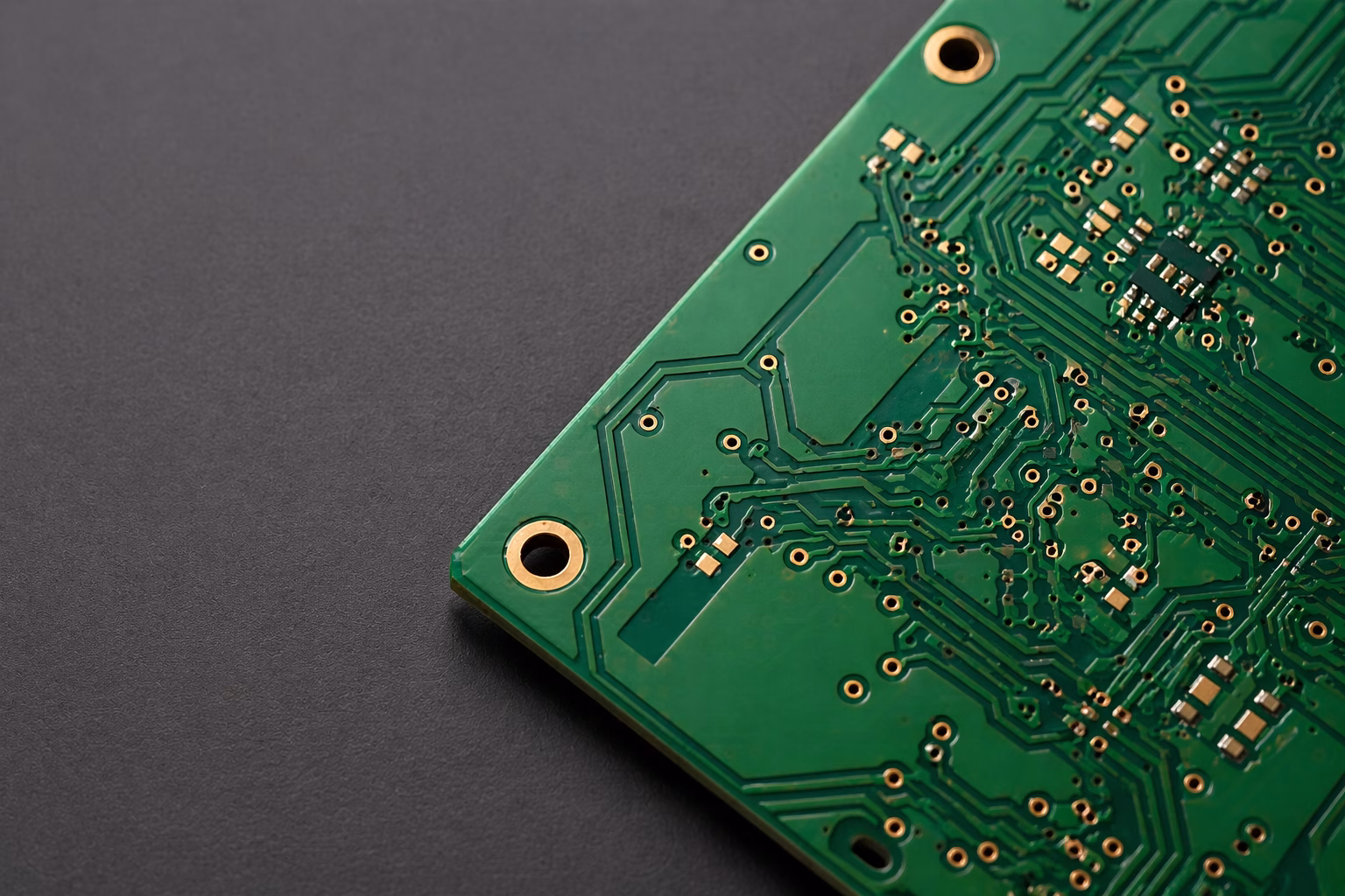
Table of Contents
- Introduktion
- Hvad er CEM-1 PCB-materiale?
- Materialer og sammensætning af CEM-1
- Vigtige egenskaber og tekniske specifikationer
- CEM-1 vs. Konkurrenterne: FR-4, CEM-3 og FR-2
- Hvor CEM-1 skinner: Almindelige anvendelser
- CEM-1 PCB-omkostningsbesparelser: Reelle tal
- Fremstilling af CEM-1 printkort: En trin-for-trin oversigt
- Overvejelser ved CEM-1 PCB-design
- CEM-1 printkort Ofte stillede spørgsmål
- Resumé
- Nøgleaftagelser:
Introduction
This guide delves deep into CEM-1 PCBs—exploring their unique composition, key characteristics, and common applications. It also provides a detailed comparison with other popular materials like FR-4, CEM-3, and FR-2, walks through the essential manufacturing steps, and unpacks the real-world cost savings on offer. By the end, you’ll have a clear understanding of why CEM-1 remains a staple in certain segments of the electronics industry, delivering significant cost savings without compromising on essential functionality.
What is CEM-1 PCB Material?
CEM-1—short for Composite Epoxy Material Grade 1—is a laminate material classified under NEMA (National Electrical Manufacturers Association) standards. It bridges the gap between basic paper-phenolic boards (like FR-2) and advanced woven glass-epoxy laminates (like FR-4), representing a cost-effective solution primarily for single-layer PCB applications.
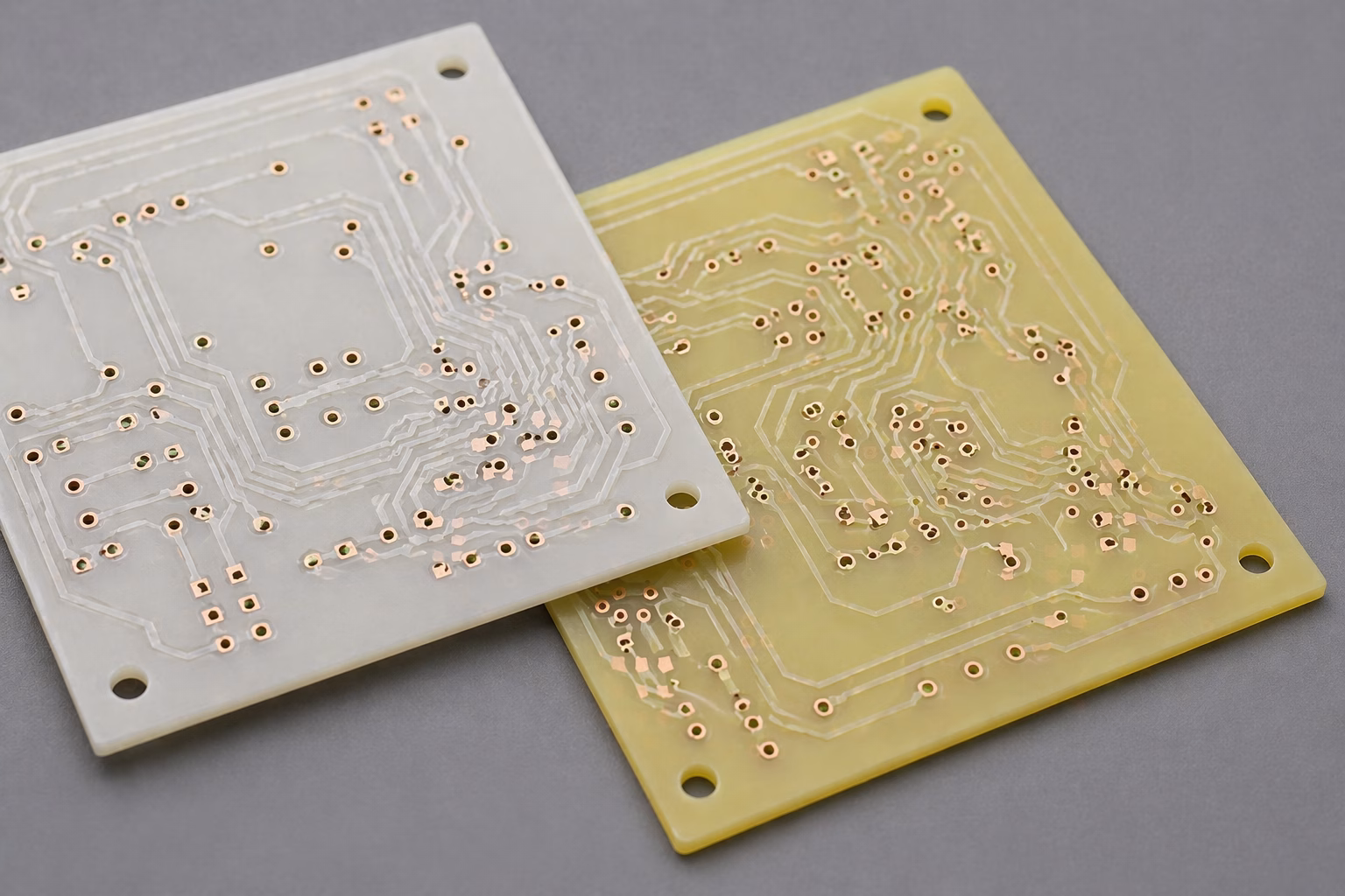
The material consists of three distinct layers: an inner cellulose paper core sandwiched between two layers of continuous woven glass fabric, all bonded together with flame-resistant epoxy resin. This construction gives CEM-1 its characteristic milky-white or milky-yellow appearance. Unlike FR-4, which uses woven fiberglass throughout, CEM-1’s paper core makes it easier to punch and process—though this same characteristic limits its use to single-layer PCB applications.
The significance of CEM-1 PCBs in the electronics industry cannot be overstated. While not suitable for high-frequency or complex multi-layer designs, it excels in applications where simplicity and cost are primary considerations. Its ability to provide stable electrical performance and decent durability makes it a go-to material for a wide range of consumer electronics and power supply units.
Materials and Composition of CEM-1
The unique properties of CEM-1 PCBs are derived directly from their composite nature. Unlike the purely woven glass fabric of FR-4 or the simple paper-phenolic of FR-2, CEM-1 combines elements to achieve its distinct characteristics. A full breakdown of the constituent layers is listed below:
- Paper Core: Cellulose-based material providing the substrate foundation. The cellulose base cannot withstand the chemical processes required for plated through-holes (PTH), which is why CEM-1 is exclusively used for single-sided PCB designs.
- Glass Fabric Layers: Woven glass cloth on both surfaces delivers mechanical strength and dimensional stability.
- Epoxy Resin Binder: Flame-resistant epoxy impregnates all layers, providing improved thermal resistance and moisture resistance compared to older phenolic resins, and contributing the UL 94 V-0 flame rating.
- Copper Foil: Single-sided copper cladding (typically 1 oz) forms the conductive traces. This single-sided configuration inherently limits CEM-1 to less complex circuit designs.
While some older descriptions mention purely paper-based cores, the established NEMA/IPC definition of CEM-1 specifically calls for the glass-fabric surface layers over the paper core—distinguishing it from FR-2 (pure paper-phenolic) and from CEM-3 (which uses non-woven glass throughout its core).
Key Properties and Technical Specifications
The suitability of CEM-1 for specific electronic designs is determined by its distinct set of properties. The table below summarizes the typical specifications you will encounter from most laminate suppliers, all compliant with the IPC-4101/10 slash sheet.
| Property | CEM-1 Value | Test Method |
| Glass Transition Temp (Tg) | 105–110°C | IPC-TM-650 |
| Dielectric Constant (1 MHz) | 4.5–5.0 | IPC-TM-650 |
| Flammability Rating | UL 94 V-0 | UL Standard |
| Peel Strength (1 oz Cu) | ≥1.05 N/mm | IPC-TM-650 2.4.8 |
| Thermal Stress (260°C) | ≥10 seconds | IPC-TM-650 2.4.13 |
| Punching Temperature | 45–70°C | Manufacturer Spec |
| Bow/Twist | ≤1.5% | IPC-TM-650 2.4.22 |
| Max Operating Temp | 105°C continuous | IPC-4101/10 |
Table 1: CEM-1 PCB Material Specifications (IPC-4101/10 compliant)
Electrical Performance
CEM-1 offers stable electrical performance suitable for many mainstream applications. The dielectric constant typically ranges from 4.5 to 5.0 at 1 MHz—adequate for most consumer electronics operating at lower frequencies. However, for high-frequency RF applications or controlled impedance designs, FR-4 or specialized high-frequency laminates are better choices. CEM-1’s insulation resistance and dielectric breakdown voltage meet the requirements for general-purpose electronics, reliably isolating traces when proper design rules are followed.
Mechanical Strength and Durability
The epoxy resin reinforcement and woven glass surface layers provide CEM-1 with decent mechanical strength, allowing it to withstand the stresses of assembly and use. It is more robust than simple paper-phenolic boards (FR-2) but less so than woven glass-based boards (FR-4), with a tensile strength of approximately 200 MPa versus F R-4’s ~300 MPa. It maintains structural integrity well in typical operating environments.
Thermal and Chemical Resistance
CEM-1 exhibits moderate thermal resistance, with a glass transition temperature (Tg) of 105–110°C and a maximum continuous operating temperature of 105°C. Its epoxy resin system provides better resistance to heat and certain chemicals compared to older paper-phenolic materials. The material can endure standard soldering processes, including lead-free wave soldering (with careful thermal profile management), but is not designed for extremely high-temperature environments where high-Tg FR-4 would be necessary.
Cost-Effectiveness
Perhaps the most compelling advantage of CEM-1 is its cost-effectiveness. The use of a paper-based core makes it significantly cheaper to produce than glass-fabric-based materials like FR-4. For manufacturers looking to reduce production costs for high-volume consumer goods, CEM-1 can offer material savings of 20–30% compared to FR-4, and additional savings arise from easier processing (punching vs. routing) and the elimination of PTH plating steps.
CEM-1 vs. The Competition: FR-4, CEM-3, and FR-2
Understanding CEM-1’s position in the PCB material landscape is best achieved by comparing it with its closest relatives and competitors. Each material serves a specific niche based on its composition, performance, and cost.
CEM-1 vs. FR-4
FR-4 is the most ubiquitous PCB material globally, primarily due to its superior performance. The fundamental difference lies in their reinforcement: FR-4 uses woven glass fabric exclusively, while CEM-1 uses a paper-based core with woven glass fabric surfaces. The table below captures the key distinctions:
| Parameter | CEM-1 | FR-4 |
| Core Material | Paper + Woven Glass | Woven Fiberglass |
| Layer Support | Single-layer only | Multi-layer (32+) |
| PTH Capability | Not suitable | Full support |
| Glass Transition (Tg) | ~110°C | 130–180°C |
| Tensile Strength | ~200 MPa | ~300 MPa |
| Moisture Absorption | Higher (paper core) | <0.15% |
| Machinability | Excellent (easy punch) | Good (requires routing) |
| Relative Cost | 20–30% lower | Baseline |
Table 2: CEM-1 vs. FR-4 Material Comparison
The bottom line: choose CEM-1 when your design is single-layer, cost-sensitive, and does not require extreme thermal or mechanical performance. Choose FR-4 for multi-layer designs, high-reliability applications, or when you need plated through-holes.
CEM-1 vs. CEM-3
CEM-3 (Composite Epoxy Material Grade 3) is often considered a close relative of both CEM-1 and FR-4. Like CEM-1, it is a composite epoxy material, but its core uses non-woven (chopped) glass fiber instead of cellulose paper. This glass core supports PTH metallization, making CEM-3 suitable for double-sided and even multi-layer PCB designs. In Asia, particularly Japan and China, CEM-3 has significant market share as a cost-effective alternative to FR-4 for consumer electronics.
- Choose CEM-1 when: Your design is single-layer, cost is the primary driver, and you need easy punching for high-volume production.
- Choose CEM-3 when: You need double-sided capability, want FR-4-like performance at lower cost, or require plated through-holes.
CEM-1 vs. FR-2
FR-2 (Flame Retardant-2) is a paper-phenolic material and one of the cheapest PCB substrates available. While both FR-2 and CEM-1 use a paper base, the key difference is the resin system: FR-2 uses phenolic resin, while CEM-1 uses epoxy resin. CEM-1’s epoxy resin delivers superior thermal stability, moisture resistance, and mechanical strength. FR-2 is cheaper but reserved for absolute simplest, lowest-cost applications, while CEM-1 offers a meaningful step up in reliability for common consumer goods.
Full Material Comparison
The following table provides a comprehensive side-by-side comparison of all four materials across the properties most relevant to PCB designers:
| Feature | CEM-1 | FR-4 | CEM-3 | FR-2 |
| Reinforcement | Paper/Cellulose + Epoxy Resin | Woven Glass Fabric + Epoxy Resin | Non-woven Glass + Woven Glass + Epoxy | Paper/Cellulose + Phenolic Resin |
| Layer Capability | Single-Sided Only | Multi-Layer (32+) | Single/Double-Sided | Single-Sided Only |
| Mechanical Strength | Good | Excellent | Very Good | Fair |
| Electrical Performance | Good (Low Freq) | Excellent (High Freq) | Very Good | Fair (Low Freq) |
| Thermal Resistance | Moderate (~110°C) | High (130–180°C) | High | Low |
| PTH Capability | No | Yes | Yes | No |
| Drillability | Good (punch-friendly) | Excellent | Very Good | Good (brittle) |
| Moisture Absorption | Higher (paper core) | <0.15% | Low | Higher |
| Cost | Low (20–30% vs FR-4) | Highest | Medium | Very Low |
| Common Use | Consumer electronics, LED, PSU | High-performance, complex boards | Automotive, industrial | Simple appliances, entry-level |
Table 3: Comprehensive PCB Material Comparison — CEM-1, FR-4, CEM-3, and FR-2
Where CEM-1 Shines: Common Applications
CEM-1 has carved out a strong position in several market segments where its cost advantages outweigh its technical limitations. The specific properties of CEM-1 make it an ideal choice for a variety of electronic products and systems, particularly those that are cost-sensitive and do not require the advanced performance of multi-layer or high-frequency PCBs.
LED Lighting Industry
This is arguably the largest market for CEM-1 PCB material. LED manufacturers choose CEM-1 because it offers the best balance between heat dissipation performance and cost. For residential and commercial LED lighting where thermal demands are moderate, CEM-1 delivers adequate performance at a fraction of aluminum-core PCB pricing. Its balanced heat dissipation characteristics make it particularly well-suited for LED driver boards and simpler lighting modules.
Consumer Electronics
- Remote controls and wireless keyboards
- Digital clocks and basic timers
- Calculators and simple electronic toys
- Power supply modules and adapters
- Basic home appliance controllers
Industrial and Automotive
- Control panels and relay boards
- Automotive dashboard indicators
- Turn signals and brake light circuits
- Industrial sensor interfaces
- Power monitoring equipment
In essence, if a product requires a printed circuit board that is robust enough for everyday use, electrically stable for basic functions, and needs to be produced at low cost, CEM-1 is often the material of choice.
CEM-1 PCB Cost Savings: Real Numbers
Let’s talk about actual cost savings, because that’s usually the primary driver for considering CEM-1. The savings come from multiple sources:
- Raw Material Cost: CEM-1 laminates typically cost 20–30% less than equivalent FR-4 material.
- Tooling Savings: Punching vs. routing reduces tool wear and processing time significantly.
- Single-Layer Design: No PTH processing eliminates plating costs and associated process steps.
- Volume Efficiency: Faster production cycles yield greater savings at high volumes.
Example calculation: For a 100 mm × 50 mm single-layer LED driver board produced in volumes of 10,000 units, switching from FR-4 to CEM-1 can save $0.15–$0.25 per board in material alone. Adding manufacturing efficiency gains, total savings can reach $2,000–$3,000 per production run.
However, cost analysis must consider the complete picture. If your application requires features that CEM-1 cannot support—PTH, multiple layers, high-temperature operation—forcing a CEM-1 solution will likely cost more in redesign and reliability issues than the material savings are worth.
Manufacturing CEM-1 PCBs: A Step-by-Step Overview
Manufacturing CEM-1 PCBs involves a series of well-defined steps, making it an accessible entry point for beginners and hobbyists into PCB fabrication. The process is generally simpler than that for multi-layer FR-4 boards.
Laminate Production
CEM-1 laminates begin with the cellulose paper core, which is impregnated with epoxy resin. This core is sandwiched between two layers of woven glass fabric, also saturated with epoxy. The entire stack is hot-pressed to cure the resin and bond the layers together. Copper foil is applied to one side during this pressing process, creating the copper-clad laminate (CCL) that forms the raw material for PCB fabrication.
Design and Preparation
The journey begins with the circuit design, typically done using EDA (Electronic Design Automation) software. Once the schematic is finalized, it is translated into a PCB layout and Gerber files—the industry standard for PCB manufacturing instructions. These files detail the copper traces, drill locations, solder mask, and silkscreen layers. For CEM-1, the design will be single-sided, meaning all components and traces reside on one side of the board.
Pattern Transfer and Etching
The copper layer on the CEM-1 substrate is coated with a photoresist material. A photolithography process, involving exposure to UV light through a film mask, hardens the exposed areas of the photoresist. The unexposed areas are washed away, leaving the underlying copper exposed. The board then undergoes chemical etching (e.g., ferric chloride) to remove the exposed copper, leaving only the desired circuit traces protected by the hardened photoresist. Finally, the remaining photoresist is stripped off, revealing the copper circuit.
Drilling and Punching/Routing
Next, holes are drilled into the PCB for component leads and mounting points. CEM-1’s paper core enables excellent punchability at 45–70°C for thicknesses up to 0.093 inches, which is a major advantage in high-volume production. For thicker boards or more complex profiles, routing machines achieve the final board dimensions. Precise drilling remains critical to avoid issues such as burring or delamination, especially for smaller holes.
Surface Finishing
Final steps include applying a solder mask (typically green) over the copper traces to protect them from oxidation and prevent solder bridges during assembly, with openings left for component pads. A silkscreen layer is then printed, adding labels for components, polarity indicators, and other useful markings. A surface finish—such as HASL (Hot Air Solder Leveling), OSP (Organic Solderability Preservative), or ENIG (Electroless Nickel Immersion Gold)—is applied to exposed copper pads to improve solderability and prevent oxidation.
Quality Considerations
When working with CEM-1 manufacturers, pay attention to incoming material quality. Reputable suppliers use Class A laminates that meet IPC-4101 specifications. Ask for material certifications and UL recognition documentation. For production volumes, request samples for PCB assembly qualification before committing to full orders.
CEM-1 PCB Design Considerations
Designing for CEM-1 requires some specific considerations that differ from standard FR-4 design practices.
Routing Optimization
Since CEM-1 only supports single-layer designs, routing optimization becomes critical. Use careful trace planning to minimize crossovers. Where crossovers are unavoidable, implement them through zero-ohm resistor jumpers or wire links rather than attempting creative routing solutions.
Component Placement
The relatively fragile nature of CEM-1 means you should avoid placing heavy components near board edges or in areas subject to mechanical stress. Distribute component weight evenly across the board surface and consider adding mechanical support for heavier parts.
Thermal Management
While CEM-1 handles moderate thermal loads well, high-power components require attention. Use adequate copper pour for heat spreading, and consider the thermal path from heat-generating components to the board surface. For LED applications, ensure sufficient copper area around LED pads for effective heat dissipation.
Recommended PCB Design Tools
- Altium Designer: Professional-grade tool with comprehensive design rule checking and manufacturing output options.
- KiCad: Free, open-source option with no board size or layer limitations; excellent for single-layer designs.
- Eagle (Autodesk Fusion 360): User-friendly interface with good library support; suitable for small to medium projects.
- EasyEDA: Web-based tool with integrated PCB ordering; ideal for quick prototyping.
- OrCAD: Industry-standard for complex designs with advanced simulation capabilities.
Need PCB Manufacturing or Assembly?
Get a free quote within 24 hours. We specialize in prototype-to-production PCB/PCBA for hardware teams worldwide.
CEM-1 PCB FAQ
What is the main advantage of CEM-1 PCBs?
The primary advantage is cost-effectiveness. Material costs run 20–30% lower than FR-4, with additional savings from easier manufacturing processes (punching versus routing) and the elimination of PTH plating steps. This makes CEM-1 ideal for high-volume consumer electronics where budget is a significant factor.
Can CEM-1 PCBs be used for multi-layer or double-sided designs?
No. CEM-1 is limited to single-sided applications. The cellulose paper core cannot withstand the chemical processes required for plated through-hole (PTH) metallization. If you need double-sided capability with cost savings, consider CEM-3 instead, whose non-woven glass core supports PTH and is compatible with double-sided and multi-layer designs.
Is CEM-1 suitable for lead-free soldering?
CEM-1 can handle lead-free soldering processes, but with limitations. The material’s lower Tg (~110°C) compared to high-Tg FR-4 (170°C+) means thermal profiles need careful management. Keep reflow peak temperatures as low as possible while still achieving proper solder joint formation, and minimize time above liquidus. For wave soldering, standard lead-free temperatures are acceptable for brief exposure.
How does CEM-1 compare to FR-4 in terms of performance?
FR-4 offers superior electrical performance (especially for high frequencies), mechanical strength (~300 MPa vs. ~200 MPa), and thermal resistance (Tg 130–180°C vs. 105–110°C) compared to CEM-1. FR-4 is suitable for complex, high-performance, and multi-layer designs, while CEM-1 is better for simpler, cost-sensitive single-layer circuits.
Can CEM-1 PCB be used in outdoor or high-humidity applications?
CEM-1 is not ideal for outdoor or high-humidity environments without proper protection. The cellulose paper core is hygroscopic (absorbs moisture), which can degrade electrical properties and mechanical strength over time. If outdoor use is required, ensure the assembly is properly conformal coated or encapsulated. For harsh environment applications, FR-4 or specialized materials are better choices.
What is the difference between CEM-1 and CEM-3?
The key difference is the core material. CEM-1 uses a cellulose paper core, while CEM-3 uses a non-woven (chopped) fiberglass core. This makes CEM-3 suitable for PTH and double-sided/multi-layer designs. CEM-1 is strictly for single-sided boards but offers lower cost and better punchability.
Summary
CEM-1 PCBs represent a cornerstone in cost-effective electronics manufacturing, providing a reliable and accessible solution for single-layer circuit board needs. Composed of a cellulose paper core sandwiched between woven glass fabric layers and bonded with flame-resistant epoxy resin—with a single copper foil layer on one surface—CEM-1 strikes an excellent balance between performance, durability, and affordability.
Its stable electrical characteristics, decent mechanical strength, and moderate thermal resistance (Tg 105–110°C, UL 94 V-0 flammability rating) make it perfectly suited for a vast array of consumer electronics, LED lighting, and power supply modules. While it does not match the high-frequency capabilities or multi-layer versatility of FR-4, it offers material cost savings of 20–30%, plus further savings from punching and simplified fabrication.
Key takeaways:
- CEM-1 is a cost-effective, single-layer PCB material with a cellulose paper core reinforced by woven glass fabric surface layers and epoxy resin.
- It meets IPC-4101/10 specifications with a Tg of 105–110°C and UL 94 V-0 flammability rating.
- Primary applications include consumer electronics, LED lighting, power supply modules, and basic industrial/automotive controls.
- CEM-1 is 20–30% cheaper than FR-4 in raw materials, with additional savings from punching and no PTH processing.
- It is limited to single-sided designs and is not suitable for PTH, multi-layer boards, high-frequency RF, or harsh environments without conformal coating.
- For double-sided needs at lower cost than FR-4, CEM-3 is the appropriate next step.

Get Quote Free