How to Improving SMT Yield Without Reducing Production Speed
Improving yield requires systematic optimization across every stage—including equipment, processes, data, personnel, and the supply chain. This article draws on industry best practices and real production experience to map out the key factors influencing SMT yield and offer actionable improvement strategies -- helping manufacturing teams push yield higher without sacrificing throughput.
Get Your PCB Quote!

Table of Contents
- 1. Osnovne metrike donosa SMT
- 2. Tiskanje s spajkalno pasto: Nadzor napak pri viru
- 3. Namestitev komponent: Zmogljivost stroja in spremljanje v realnem času
- 4. Spajkanje s ponovnim spajkanjem: Toplotni profil je vse
- 5. Avtomatiziran pregled: Ustavite napake, preden se razširijo naprej
- 6. Operacije, ki temeljijo na podatkih: SPC in inteligentna analitika za proaktivno preprečevanje
- 7. Načrtovanje za izdelovalnost (DFM): Odpravljanje napak v fazi načrtovanja
- 8. Usposabljanje operaterjev in standardizirani postopki: človeški dejavnik
- 9. Upravljanje kakovosti dobavne verige: Nadzor vhodnih materialov
- 10. Vitka proizvodnja in nenehno izboljševanje: gradnja trajnega sistema
- zaključek
1. Core SMT Yield Metrics
Before driving yield improvement, you need a clear measurement framework. The following KPIs form the foundation for assessing the health of any SMT production line:
| Metric | Definition | Industry Benchmark |
| First Pass Yield (FPY) | Percentage of boards passing inspection without rework | >= 99% |
| Defect Density (DPPM) | Number of defects per million solder joints | < 100 DPPM |
| Overall Equipment Effectiveness (OEE) | Composite of availability, performance, and quality rate | >= 85% |
| Throughput | Number of good boards completed per unit time | Product-dependent |
| Process Capability (CPk) | Stability and variation control of key process parameters | >= 1.67 |
Understanding how these metrics interact is the prerequisite for effective improvement. For example, a drop in FPY often traces back to drift in a critical process parameter — such as solder paste height or reflow peak temperature — which CPk monitoring can flag early enough to prevent a quality escape.
2. Solder Paste Printing: Controlling Defects at the Source
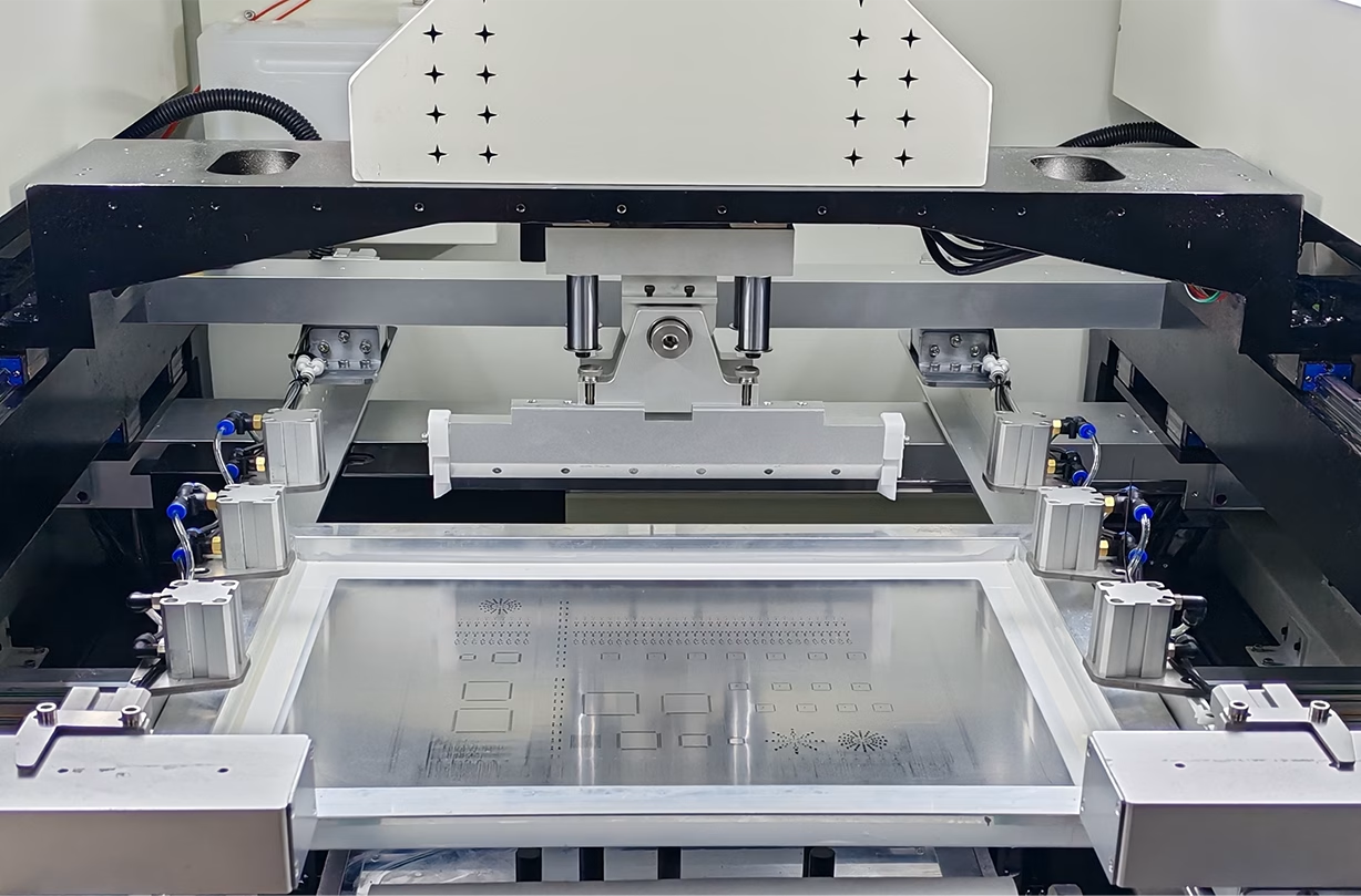
Industry data consistently shows that approximately 50% of all SMT soldering defects originate in the solder paste printing process. Print quality directly affects placement and reflow outcomes downstream, making this the highest-leverage point for defect prevention.
2.1 Equipment Precision and Stencil Management
Modern fully automatic printers are equipped with inline 3D Solder Paste Inspection (SPI) systems capable of measuring paste height, area, and volume at 12-bit resolution in real time. High-quality printing equipment should deliver:
- Product changeover in 15 minutes or less
- 100% inline inspection coverage with CPk >= 1.67
- Automatic alarm and line halt when consecutive defect trends are detected
Stencil quality is equally critical. The aperture accuracy of laser-cut stencils directly controls paste deposition volume. Regular stencil cleaning and wear inspection are essential to maintaining print consistency over time.
2.2 Process Parameter Optimization
Squeegee pressure, print speed, and separation speed are the three parameters with the greatest influence on paste deposition. It is strongly recommended to optimize these systematically through Design of Experiments (DOE) rather than relying on intuition. Typical control ranges to reference:
- Squeegee pressure: 3-8 N/cm — too high scrapes paste away, too low leaves insufficient deposit
- Print speed: 20-80 mm/s — must be matched to paste viscosity
- Separation speed: 0.1-3 mm/s — too fast causes paste stringing and short-circuit risk
3. Component Placement: Machine Capability and Real-Time Monitoring
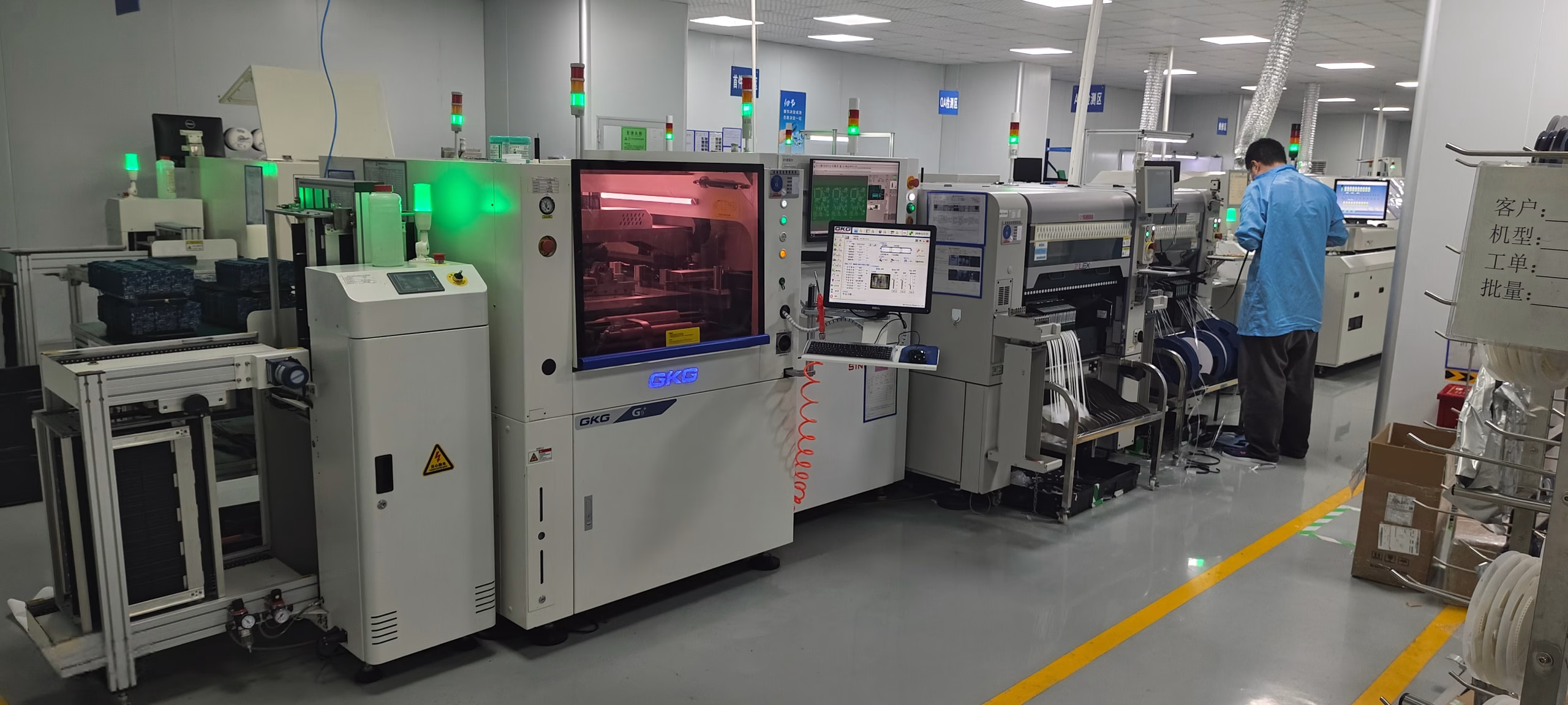
High-speed pick-and-place machines can achieve placement accuracy of +-0.025 mm and DPPM below 100. But equipment capability alone is just the starting point — sustaining that quality requires proactive maintenance and monitoring.
3.1 Periodic Calibration and Preventive Maintenance
Equipment calibration is the foundation of sustained placement accuracy. A standardized maintenance schedule should include:
- Weekly: Inspect and calibrate reflow oven thermocouples to keep temperature deviation within +-5 degrees C
- Monthly: Clean and inspect pick-and-place nozzles to prevent blockages causing placement offset
- Quarterly: Full verification of SPI systems to ensure measurement accuracy meets the 20 micrometer standard
Field data shows that systematic preventive maintenance can reduce unplanned downtime by more than 12% and deliver measurable OEE improvement.
3.2 Vision Alignment Systems
Modern pick-and-place machines use vision alignment systems to identify PCB fiducial marks in real time and automatically compensate for board position variation. Combined with live monitoring, operators can detect placement anomalies immediately, preventing systemic offset from propagating through an entire batch. One automotive electronics customer who implemented real-time vision monitoring saw component placement defects fall by 25% while production throughput increased by 40%.
4. Reflow Soldering: The Thermal Profile Is Everything

Reflow soldering is one of the most technically demanding steps in the SMT process. The thermal profile configuration directly determines solder joint reliability.
4.1 Thermal Profile Optimization
A well-optimized reflow profile typically comprises four zones: preheat, soak, reflow, and cooling. Parameter settings for each zone must account for paste characteristics, component heat tolerance, and PCB material:
| Profile Zone | Control Target | Impact on Solder Joint Quality |
| Preheat (Ramp-Up) | Ramp rate <= 3 degrees C/s | Prevents thermal shock damage to components |
| Soak (Activation) | 150-180 degrees C for 60-90 seconds | Activates flux fully and removes oxidation |
| Reflow (Peak) | Lead-free: 235-250 degrees C | Governs solder wetting and joint formation |
| Cooling | Cool rate <= 6 degrees C/s | Determines grain structure and joint reliability |
Research data shows that a systematically optimized thermal profile can reduce soldering defects — including voids, tombstoning, and bridging — by up to 60%. Nitrogen or vacuum reflow processes can further reduce internal void rates and extend solder joint fatigue life.
4.2 Profile Verification and Ongoing Monitoring
Setting parameters is not enough — you need to periodically verify the actual reflow profile using a thermal profiler. Re-verification is recommended in the following situations:
- New product introduction
- Change in solder paste brand or formulation
- Significant seasonal shift in shop floor ambient temperature
- After equipment maintenance or heating element replacement
5. Automated Inspection: Stop Defects Before They Flow Downstream
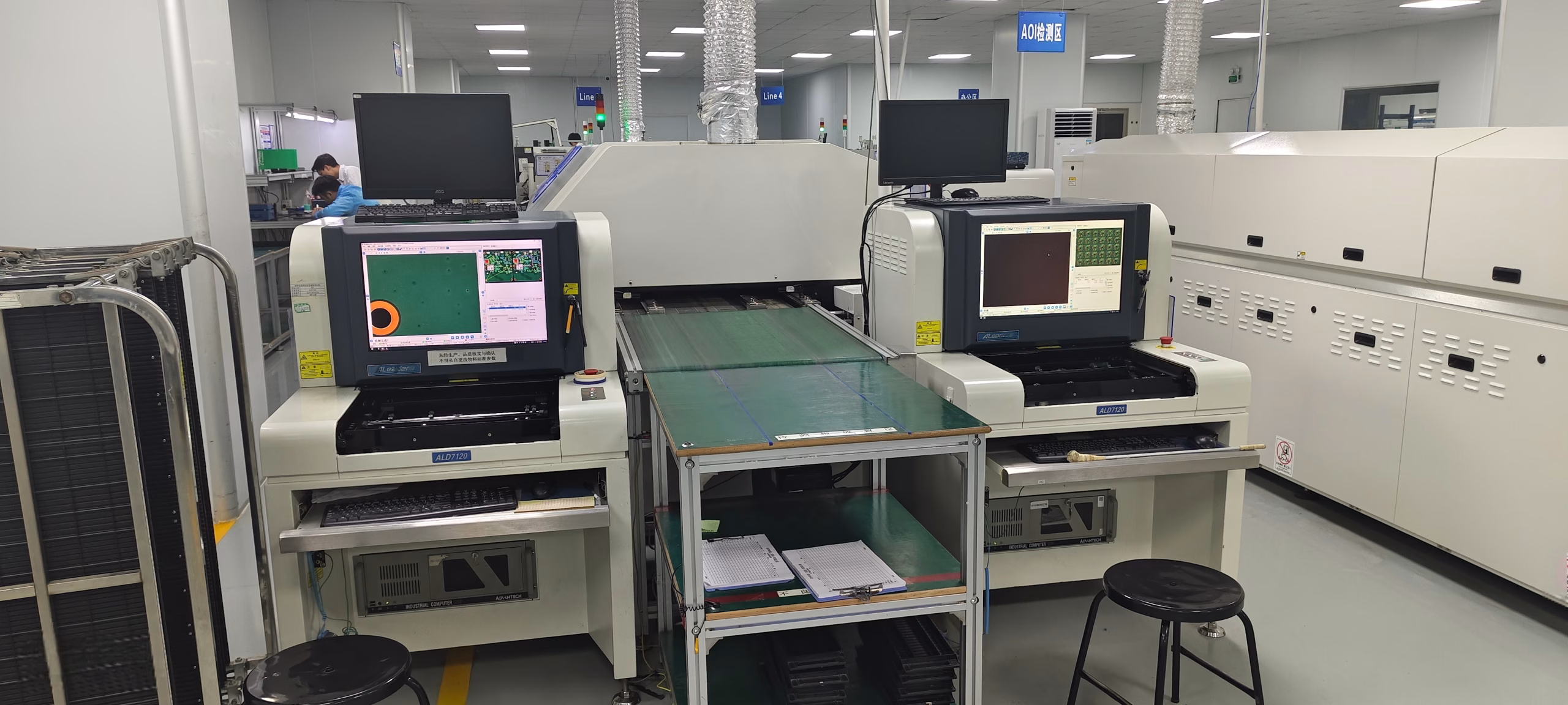
Inspection does not create good boards, but it prevents defective boards from reaching the next process step — reducing rework cost and delivery delays. A modern SMT line should deploy a multi-layer inline inspection architecture.
5.1 AOI Deployment Strategy
Automated Optical Inspection (AOI) systems use high-resolution cameras and image processing algorithms to rapidly identify missing components, placement offsets, polarity reversals, and solder bridges. Deploying a deep-learning-based AOI system delivers:
- Defect detection rate raised to over 97%
- Missed defects reduced by 85%; false positive rate down by 40%
- FPY improved from 92% to 98%
- Rework cost savings of up to 60% annually on high-volume lines
AOI should be deployed at two critical checkpoints: after solder paste printing (as SPI) and after reflow soldering. The defect data captured by AOI should feed back into upstream processes to close the improvement loop.
5.2 X-Ray Inspection Use Cases
For components with hidden solder joints — such as BGAs and QFNs — X-ray inspection is the only effective means of evaluating joint quality. X-ray clearly reveals internal voids, bridging, and open connections. In high-reliability applications such as medical devices and aerospace, it is indispensable.
6. Data-Driven Operations: SPC and Intelligent Analytics for Proactive Prevention
The most efficient SMT factories have made the shift from reactive defect detection to proactive defect prevention. The engine driving that shift is rigorous data collection, analysis, and closed-loop feedback.
6.1 Statistical Process Control (SPC)
SPC applies real-time statistical analysis to critical process parameters — solder paste height, placement offset, reflow profile, and more — enabling early warning before quality problems escalate. When a parameter’s CPk falls below 1.33, process stability is insufficient and intervention is needed immediately.
Key elements of an effective SPC implementation:
- Define Key Control Characteristics (KCCs) and their specification limits for each process step
- Establish control charts with appropriate control limits (typically +-3 sigma)
- Define clear out-of-control action rules (e.g., alarm when 7 consecutive points fall on the same side of the mean)
- Link SPC data to equipment parameters to enable rapid root-cause traceability
6.2 AI and Machine Learning Applications
As Industry 4.0 matures, more factories are integrating machine learning into SMT process control. AI systems can analyze data streams from SPI, pick-and-place, reflow ovens, and AOI simultaneously — recognizing correlation patterns that human engineers would miss:
- Predict the next required maintenance window based on historical data, eliminating unplanned breakdowns
- Correlate AOI defect images with process parameter logs to pinpoint root causes rapidly
- Recommend real-time thermal profile adjustments that adapt to ambient temperature and humidity changes
In practice, production lines that have adopted AI-assisted analytics have achieved an additional 15-30% reduction in defect rates, while dramatically improving engineering analysis efficiency.
7. Design for Manufacturability (DFM): Eliminating Defects at the Design Stage
Many SMT production problems are rooted in decisions made during PCB design. Driving DFM reviews is one of the most cost-effective levers for reducing systemic defects. Key areas to scrutinize during a DFM review include:
- Pad dimensions — do they conform to IPC standards? Pads that are too large or too small both cause soldering defects
- Component spacing — does it meet the minimum nozzle clearance requirements of the placement equipment?
- Thermal management in high-density areas — are adequate thermal vias planned to dissipate heat during reflow?
- Panelization design — are V-cut or tab-routed break-away tabs positioned to support automated handling without warping?
- Large or heavy components — will their placement interfere with airflow uniformity through the reflow oven?
Statistics show that investing one dollar in DFM optimization at the design stage saves ten dollars or more in rework and scrap costs during production. Engineers should conduct a joint review with the manufacturing team before PCB layout is finalized, bringing production knowledge forward into the design process.
8. Operator Training and Standardized Procedures: The Human Factor
Even on highly automated SMT lines, operator capability and discipline have a measurable impact on yield. Research shows that operators who complete systematic training programs reduce error rates by up to 20%.
8.1 Building Standardized Work Instructions (SWI)
Every workstation should have detailed Standard Work Instructions (SWI) covering equipment operation steps, changeover procedures, abnormality handling protocols, and first-article inspection requirements. SWIs should be visual and clear enough for operators at all experience levels to execute accurately.
The impact of changeover efficiency on yield is often underestimated. Case studies show that through process redesign and tool pre-staging, changeover time can be compressed from an average of 15 minutes to under 2 minutes — improving equipment utilization and reducing the early-defect risk that comes with poorly executed changeovers.
8.2 Tiered Skills Certification
Consider implementing a tiered skills certification framework that links operator competency to compensation progression, motivating proactive self-improvement. Training content should cover:
- SMT process fundamentals — helping operators understand the ‘why,’ not just the ‘how’
- Daily equipment maintenance and inspection routines
- Defect recognition and rapid escalation protocols
- ESD (Electrostatic Discharge) protection and material handling standards
9. Supply Chain Quality Management: Gatekeeping Incoming Materials
SMT yield is not purely an internal process issue — incoming material quality is equally critical. Defective solder paste, warped PCBs, or moisture-damaged components can introduce defects that are extremely difficult to trace once they reach the production floor.
9.1 Standardized Incoming Quality Control (IQC)
Different material types require differentiated IQC inspection protocols:
| Material | Inspection Method | Key Inspection Points |
| PCBs | Visual inspection + flatness measurement | Warpage, hole position accuracy, surface oxidation |
| Components | Electrical parameter testing | Resistance/capacitance values, polarity, physical damage |
| Solder Paste | Viscosity test + composition verification | Viscosity consistency, expiration date, open-time tracking |
| Solder Wire/Bar | Visual inspection + melting point check | Surface oxidation, diameter/purity |
9.2 Collaborative Supplier Improvement
Establish regular quality communication channels with key suppliers — sharing defect data and improvement requests to drive their continuous improvement. A supplier rating system that ties quality performance to purchase volume allocation creates healthy competitive incentives and builds a stronger, more reliable supply base.

10. Lean Production and Continuous Improvement: Building a Lasting System
Yield improvement is not a one-time project — it is a system that requires sustained investment. Lean manufacturing principles provide a mature methodological framework for this ongoing journey.
10.1 Value Stream Mapping (VSM) to Identify Bottlenecks
By mapping the value stream of SMT production, you can visualize cycle times, work-in-process accumulation, and waiting waste at each process step. Concentrating improvement resources on the identified bottleneck steps typically delivers the greatest overall line throughput and yield benefit.
10.2 Kaizen Team Activities
Encouraging frontline operators to participate in Kaizen (continuous improvement) activities — focusing on one specific problem each week and working through the PDCA cycle of [Identify problem > Analyze root cause > Implement countermeasure > Verify effect > Horizontal deployment] — not only generates a steady stream of improvement results but also cultivates a culture where quality is everyone’s responsibility.
10.3 Daily KPI Visualization
Displaying core metrics such as FPY, DPPM, and OEE on production-floor dashboards in real time ensures that every team member can see the current state against targets. Regular quality review meetings to share improvement results and recognize contributions embed quality culture into daily management rather than treating it as a periodic audit exercise.
Conclusion
Achieving and sustaining SMT yield above 99.5% has no shortcuts — but it does have a clear playbook. From source control at solder paste printing, to temperature optimization in reflow soldering, to comprehensive inline inspection deployment, to data-driven intelligent decision-making, systematic people development, and collaborative supply chain management — every link in the chain is a load-bearing pillar of yield performance.

Get Quote Free