What is FR1 PCB? Difference From FR2, FR3, and FR4
FR1 PCB is a flame-retardant, low-cost material made from paper and phenolic resin. FR1 is less robust and thermally stable compared to FR4. FR-1 materials are used for low-cost applications that don't require high-performance or complex circuitry.
Get Your PCB Quote!
Table of Contents
1. Introduction
Often overlooked in favor of its more robust counterparts, FR1 stands out as an economical and practical choice for a broad spectrum of electronic products. This guide explores FR1 PCB material in depth — covering its composition, structural layers, material properties, manufacturing process, advantages, limitations, and typical applications. We also provide detailed comparative analysis with FR-2, FR-3, and FR-4, along with practical design guidelines, so you can quickly determine when FR1 is the optimal choice for your next project.
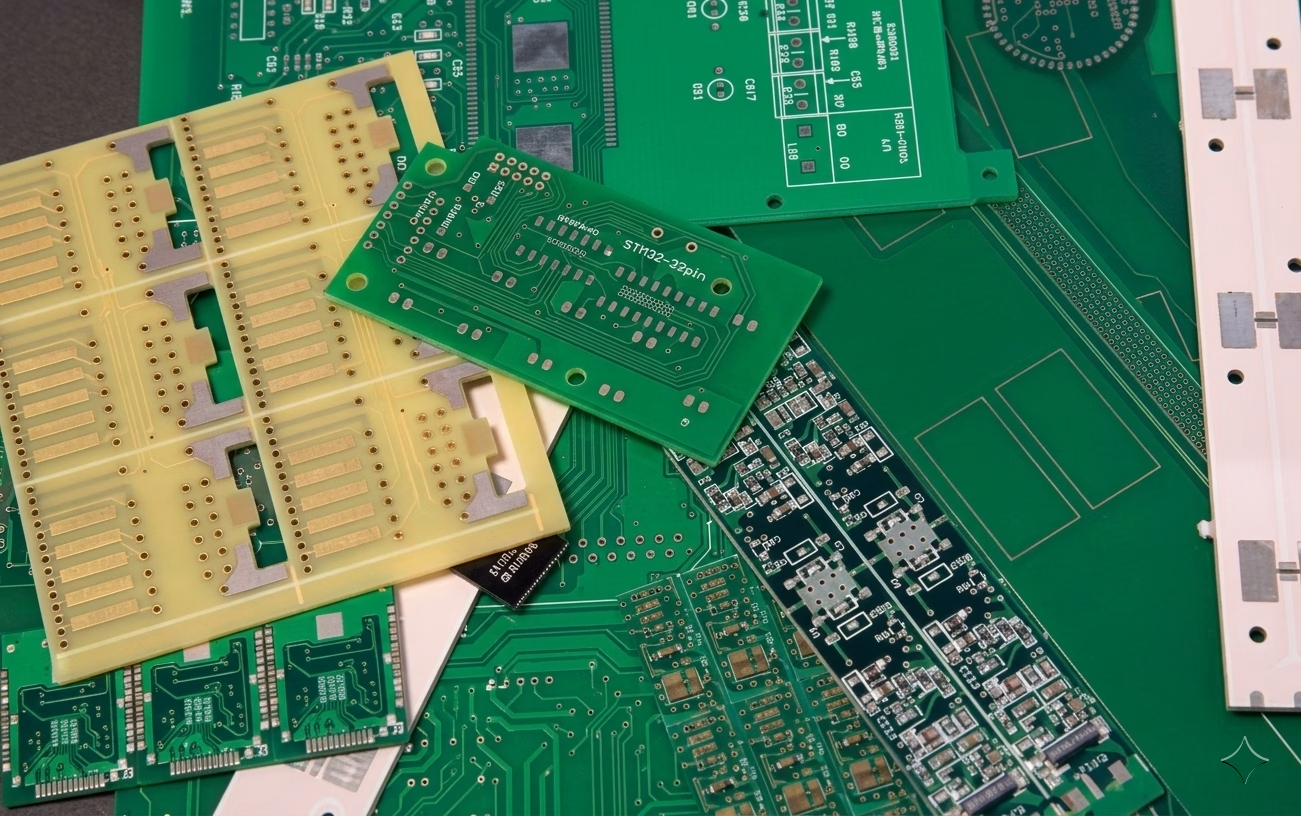
2. What Is FR1 PCB Material?
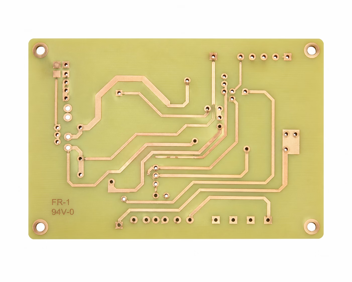
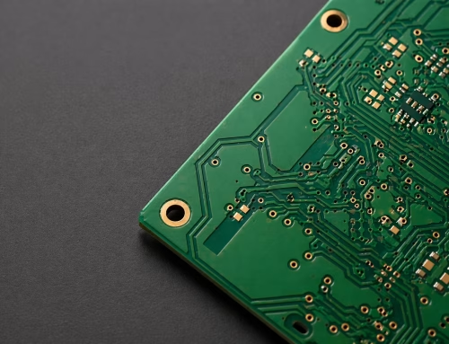
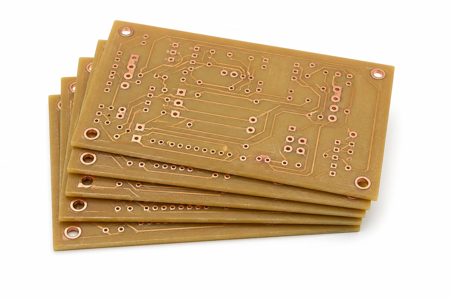
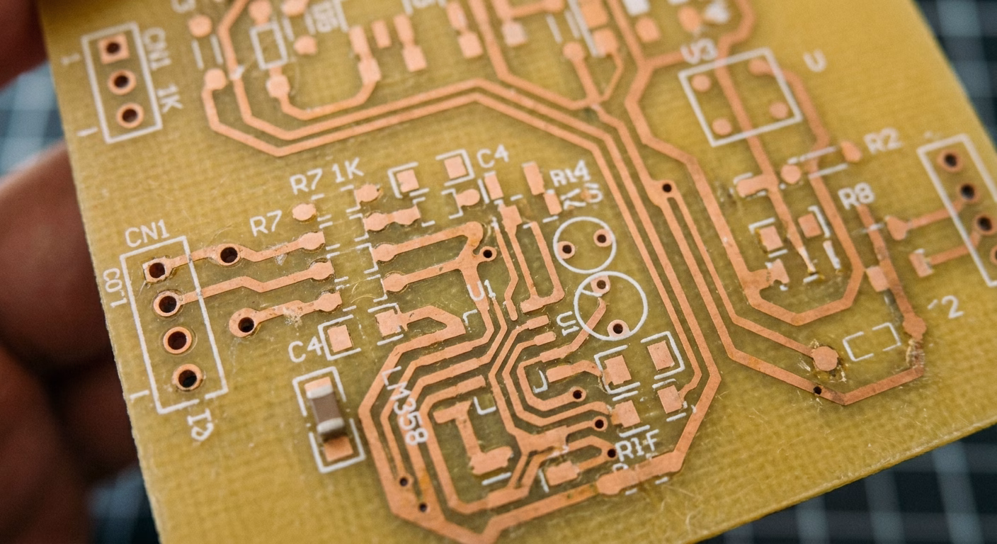
FR1 is a rigid, flame-retardant laminate manufactured from cellulose paper impregnated with phenol-formaldehyde (phenolic) resin. The designation “FR” stands for Flame Retardant, while “1” identifies it as the original formulation in the IPC/IEC classification system. The material meets IPC-4101 /21 & /22 specifications and conforms to UL 94 V-0 flammability standards.
In practical terms, FR1 is a hard, flat copper-clad laminate — the foundation for etching circuit traces. Compared with fiberglass-based FR-4, the core of FR1 is entirely paper-based, which keeps costs very low and makes it ideal for mass production of single-layer consumer electronics.
FR1 PCB Layer Structure
A standard FR1 PCB consists of the following layers:
Copper Foil (18–70 μm): The copper layer is thin to reduce cost, yet sufficient for simple circuit conduction. Typical weight is 1 oz (35 μm).
Phenolic Paper Core: Cellulose paper impregnated with phenolic resin provides basic mechanical strength and flame-retardant performance.
Adhesive Layer: Bonds the copper foil firmly to the paper substrate, maintaining structural stability.
Solder Mask (Optional): Many low-cost FR1 products omit the solder mask to further reduce manufacturing expenses.
Silkscreen Layer: Used for component markings, text, and reference indicators in standard mass-production.
3. Composition and Manufacturing Process
The strength and unique characteristics of FR1 PCB material stem from its straightforward composition and multi-step manufacturing process.
Material Components
Paper Base: High-quality cellulose paper provides mechanical structure and thickness. This is fundamentally different from the woven fiberglass used in FR-4, which explains many of the performance differences between the two materials.
Phenolic Resin: Phenol-formaldehyde resin acts as the binder, impregnating the paper to create a rigid, insulating substrate. It also gives FR1 its characteristic brown color and self-extinguishing behavior when exposed to flame.
Copper Foil: A thin copper layer (typically 1 oz / 35 μm) is laminated onto one side of the resin-impregnated paper, forming the base for circuit traces.
Manufacturing Steps
Resin Impregnation: Rolls of cellulose paper are fed through a bath of liquid phenolic resin, thoroughly saturating the paper fibers.
Drying (B-stage): The resin-impregnated paper passes through ovens, partially curing the resin into a pliable “prepreg” state.
Lamination: Prepreg layers are stacked with copper foil and placed into a high-temperature, high-pressure press.
Curing: Under heat and pressure, the phenolic resin fully cures, creating a hard, rigid laminate with the copper permanently bonded to the substrate.
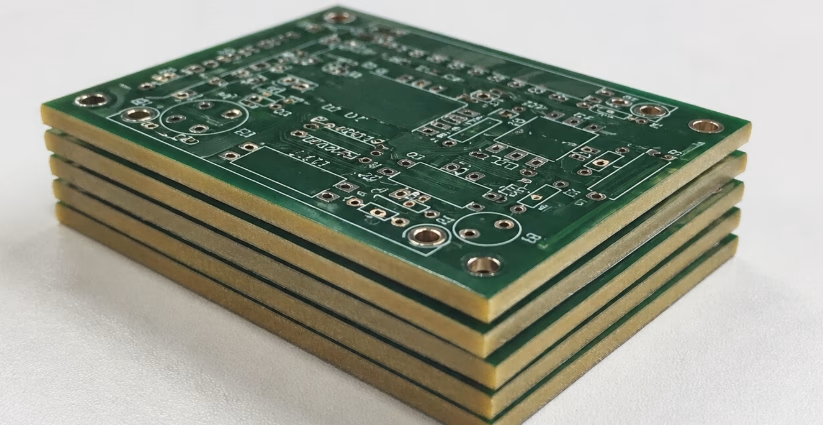
Cutting and Finishing: Large laminated sheets are cut into usable PCB blanks ready for circuit fabrication. Standard thickness ranges from 1.5 mm to 1.6 mm.
4. FR1 PCB Technical Specifications
The table below provides the key technical data required for design decisions when working with FR1 PCB material:
| Property | FR1 Value / Range | Notes |
| Glass Transition Temperature (Tg) | 125–135°C | Below this, FR1 is rigid; above, it softens |
| Decomposition Temperature (Td) | < 260°C | Limits exposure to high-temperature processes |
| Dielectric Constant (Dk @ 1 MHz) | 4.0–5.5 (typically ~5.0–5.1) | Stable for low-frequency circuits |
| Dissipation Factor | ~0.03 | Acceptable for power and simple analog designs |
| Volume Resistivity | 10⁸–10⁹ Ω·cm | Lower than fiberglass laminates |
| Standard Thickness | 1.5 mm – 1.6 mm | Equivalent to approx. 2–3 stacked credit cards |
| Copper Weight | 1 oz (35 μm) typical | 18–70 μm range available |
| Maximum Operating Temperature | 130°C | Exceeding this causes softening and dimensional loss |
| Thermal Conductivity | 0.2–0.3 W/m·K | Weak; not suited for high-power dissipation |
| Moisture Absorption | Moderate to High | Sensitive to humidity; avoid outdoor/marine use |
| Comparative Tracking Index (CTI) | ≥ 150 V | Sufficient for typical consumer voltage levels |
| Flammability Rating | UL 94 V-0 | Self-extinguishing; meets safety standards |
| IPC Standard | IPC-4101 /21 & /22 | Basis for specifying material to manufacturers |
| Max Reflow Capability | Not suitable for Pb-free reflow | Wave soldering only, under controlled conditions |
| Layer Configuration | Single-sided only | Not designed for multilayer lamination |
5. Key Properties of FR1 Material
Electrical Properties
| Property | Typical Value | Notes |
| Dielectric Constant (Dk @ 1 MHz) | ~5.0–5.1 | Stable enough for low-frequency circuits |
| Dissipation Factor | ~0.03 | Acceptable for power and simple analog designs |
| Volume Resistivity | 10⁸–10⁹ Ω·cm | Lower than fiberglass laminates |
| Insulation Resistance | Moderate | Sensitive to humidity; degrades in wet environments |
FR1’s dielectric constant is not as stable or low as materials designed for high-frequency applications. Signal loss becomes significant above approximately 30 MHz, making it unsuitable for RF or high-speed digital circuits.
Thermal Properties
| Parameter | FR1 Typical Range |
| Glass Transition Temperature (Tg) | 125–135°C |
| Decomposition Temperature (Td) | < 260°C |
| Maximum Reflow Capability | Not suitable for Pb-free reflow |
| Heat Resistance | Low |
| Thermal Conductivity | 0.2–0.3 W/m·K (Weak) |
The relatively low Tg is a key reason FR1 is not recommended for SMT assembly using lead-free soldering. Wave soldering is possible only under carefully controlled temperature profiles below 245°C.
Mechanical Properties
| Property | Notes |
| Punchability | Excellent — ideal for high-volume die-cutting and stamping; entire outlines, slots, and keyholes cut in milliseconds |
| Bending Strength | Lower than FR-2 or FR-4; not suitable for heavy component mounting |
| Drill Quality | Lower hole-wall integrity; prone to burrs; not suitable for many plated-through holes |
| Warpage Resistance | Limited — avoid designs requiring tight dimensional tolerances |
| Density / Weight | ~15% lighter than FR-4 at the same thickness; suited for compact, cost-sensitive products |
Environmental and Safety Performance
- Complies with basic flame-retardant requirements (UL 94 V-0).
- RoHS-compliant variants are available; meets REACH requirements.
- Lower moisture resistance than FR-3 or FR-4; paper-based laminates absorb moisture more easily and degrade faster under thermal cycling.
- Not suitable for harsh, outdoor, or marine environments.
6. Advantages of Choosing FR1 PCBs
Exceptional Cost-Effectiveness
FR1 is approximately 40–60% cheaper than FR-4 at the raw material level (roughly $0.90/sq ft vs $2.75/sq ft). Combined with punching-based fabrication — which is faster and less tool-intensive than CNC routing — the total manufacturing cost advantage is substantial for high-volume production runs exceeding 10,000 units.
Superior Punchability for High-Volume Production
The paper core allows for rapid die-cutting and mechanical punching without generating the hazardous glass-fiber dust associated with FR-4. Complete board outlines, mounting slots, and keyholes can be cut in milliseconds, enabling fast batch production cycles that reduce tooling costs significantly.
Stable Electrical Performance for Low-Frequency Circuits
Although FR1’s dielectric performance is not comparable to FR-4, it is more than sufficient for low-frequency and low-voltage applications such as AC-DC mini power supplies, buzzer circuits, indicator light drivers, and basic switch circuits.
Lightweight and Safe Machining
FR1 is approximately 15% lighter than FR-4 at the same thickness. It can also be machined on desktop CNC equipment without producing hazardous fiber dust, making it a safer and more accessible option for prototyping and hobbyist environments.
Reliable Flame Retardancy
Meeting UL 94 V-0 flammability standards, FR1 is self-extinguishing — a crucial safety requirement for consumer-facing products. This property helps prevent fire spread in case of electrical malfunction or component overheating.
Mature Supply Chain
Nearly all PCB fabricators stock FR1 as a standard single-sided material. The supply chain is mature, with short lead times, making it especially suitable for customers with tight delivery requirements.
7. Limitations and Considerations
Not for High-Frequency Applications
FR1’s dielectric properties are not optimized for high-frequency signals. Signal integrity degrades significantly above approximately 30 MHz, ruling it out for RF, Wi-Fi modules, or high-speed digital circuits.
Poor Heat Resistance
With a Tg of 125–135°C, FR1 cannot withstand the peak temperatures of lead-free reflow soldering (≥245°C). Even during wave soldering, temperature must be carefully controlled to avoid blistering, delamination, or board deformation.
Not Suitable for Multilayer or Double-Sided Boards
FR1 is limited to single-sided configurations. The paper-based structure cannot withstand the heat and pressure required for multilayer lamination, and the material does not support the through-hole plating process needed for double-sided connectivity.
Limited Mechanical Strength
Drilling through FR1 tends to produce burrs and poor hole-wall integrity. Heavy components such as transformers or press-fit connectors should be avoided. The material is also more prone to warpage than fiberglass-based alternatives.
High Moisture Absorption
Compared to fiberglass-based materials, FR1 absorbs moisture more readily. This can cause swelling, dielectric constant fluctuations, reduced insulation resistance, and dimensional instability — particularly problematic in humid, outdoor, or marine environments.
8. Typical Applications of FR1 PCBs
FR1 PCB excels where cost, simplicity, and flame retardancy take priority over high-frequency performance, thermal endurance, or multilayer complexity. Common real-world applications include:
Consumer Electronics
- Remote controls for TVs, air conditioners, and garage door openers
- Basic calculators, alarm clocks, and electronic toys
- Simple audio equipment and novelty items
- LED lighting fixtures and basic driver boards
Power Electronics
- Low-cost AC/DC adapters and small chargers
- Simple power supplies and low-power distribution boards
- 120V/230V appliance controls (with proper creepage distances)
Household and Industrial Applications
- Household electronics: coffee makers, kettles, irons
- Timers, buzzers, and beepers
- Control panels and instrumentation displays with basic functionality
- Button interfaces and membrane switch backing
- Disposable or semi-disposable electronic products
Education and Prototyping
- Educational electronics kits and classroom projects
- Hobbyist circuits and prototyping (desktop CNC milling preferred over FR-4 for its dust-free machining)
9. FR1 vs. FR-2, FR-3, and FR-4: Complete Comparison
The tables below provide a structured comparison to support material selection decisions across the full FR material family.
9.1 Core Material Properties
| Property | FR1 | FR-2 | FR-3 | FR-4 |
| Base Material | Cellulose Paper + Phenolic Resin | Cotton Paper + Phenolic Resin | Paper + Epoxy Resin | Woven Fiberglass + Epoxy Resin |
| Tg (°C) | 125–135°C | ~105°C | 105–150°C | 130–180°C+ |
| Flammability | UL 94 V-0 | UL 94 V-0 | UL 94 V-0 | UL 94 V-0 |
| Moisture Resistance | Poor | Fair | Good | Excellent |
| Thermal Conductivity | 0.2–0.3 W/m·K | 0.2–0.3 W/m·K | Moderate | 0.3–0.4 W/m·K |
| Color | Brown | Brown / Yellow | Brown | Green / Yellow |
| Market Share | ~5% | ~3% | ~2% | ~90% |
9.2 Thermal Performance
| Material | Tg | Heat Endurance | Pb-Free Reflow |
| FR1 | 125–135°C | Low | Not supported |
| FR-2 | ~105°C | Low–Medium | Not supported |
| FR-3 | 105–150°C | Medium | Limited |
| FR-4 | 130–180°C+ | High | Fully supported |
9.3 Manufacturing Compatibility
| Process | FR1 | FR-2 | FR-3 | FR-4 |
| Punching / Die-Cutting | Excellent | Good | Poor | Not suitable |
| Drilling | Poor (burrs) | Medium | Medium | Excellent |
| Through-Hole Plating | Limited | Good | Good | Excellent |
| Lead-Free SMT Reflow | Not supported | Not supported | Partial | Fully supported |
| Wave Soldering | Yes (controlled) | Yes | Yes | Yes |
| Multilayer Lamination | No | No | Rarely | Yes (standard) |
9.4 Electrical and Mechanical Performance
| Property | FR1 | FR-2 | FR-3 | FR-4 |
| High-Frequency Performance | Poor (> ~30 MHz) | Poor | Fair | Excellent |
| Dielectric Constant (Dk) | 4.0–5.5 | ~4.5–5.0 | ~4.0–4.5 | ~4.0–4.5 |
| Mechanical Strength | Low | Low–Medium | Medium | High |
| Punchability | Excellent | Good | Limited | None |
| Layers Supported | Single only | Single / limited double | Single / double | Multi-layer standard |
| Through-Hole Quality | Poor | Poor–Fair | Fair | Excellent |
9.5 Cost and Production Economics
| Factor | FR1 | FR-2 | FR-3 | FR-4 |
| Raw Material Cost (approx.) | ~$0.90/sq ft (Lowest) | Low | Medium | ~$2.75/sq ft (Highest) |
| Relative Cost Index | 100% (baseline) | ~110% | ~160% | ~300% |
| Processing Method | Punch / die-cut | Punch / drill | Drill | CNC route / drill |
| Typical Scrap Rate | ~3% | ~2% | ~1% | ~0.5% |
| Best Volume | 10,000+ units | 10,000+ units | 1,000+ units | All volumes |
Need PCB Manufacturing or Assembly?
Get a free quote within 24 hours. We specialize in prototype-to-production PCB/PCBA for hardware teams worldwide.
10. Material Selection Guide
Use the decision criteria below to determine which FR material is the best fit for your project:
| If your project requires… | Choose |
| Lowest possible cost, single-layer, wave soldering, high volume, short product lifecycle | FR1 |
| Better mechanical strength with paper-based economics, epoxy resin reliability, wave soldering | FR-2 |
| Higher Tg than FR1/FR-2, limited SMT, double-sided capability, improved electrical stability | FR-3 |
| Multilayer stackups, lead-free reflow, high-speed/RF circuits, long-term reliability, harsh environments | FR-4 |
11. Design Guidelines for FR1 PCB Projects
If FR1 has been selected for your project, the following practical guidelines will help avoid common pitfalls during design and fabrication.
Trace and Spacing Recommendations
| Parameter | Minimum | Recommended |
| Trace Width | 0.2 mm (8 mil) | 0.3 mm+ (12 mil+) |
| Trace Spacing | 0.2 mm (8 mil) | 0.3 mm+ (12 mil+) |
| SMD Pad Size | 0.4 mm | 0.5 mm+ |
| Drill / Hole Size | 0.6 mm | 0.8 mm+ |
| Board Edge Clearance | 0.3 mm | 0.5 mm+ |
Soldering and Assembly Considerations
- Keep wave or selective solder profiles below 245°C to prevent delamination or warpage.Use Sn-Pb solder:
- (e.g., large transformers or press-fit connectors) due to limited mechanical strength.Avoid BGA packages and heavy components
- HASL (tin-lead), ENIG, Immersion Silver, and OSP all work with FR1.Supported surface finishes:
- can be applied for trace protection; solder mask is optional and often omitted on the lowest-cost boards.Standard LPI solder mask
- Peak temperatures of ≥245°C in lead-free soldering will damage the material.Do not use lead-free reflow:
How to Specify FR1 for Manufacturing
When ordering FR1 PCBs from PCBAndAssembly, please include the following information in your technical documentation:
- Material: FR1 per IPC-4101/21 or /22
- Thickness: 1.6 mm (or specify)
- Copper Weight: 1 oz (35 μm)
- Surface Finish: HASL (Sn-Pb), ENIG, or Immersion Silver
- Solder Mask: Green LPI (or specify color)
- Silkscreen: White (single side)
12. FR1 PCB FAQ
Q: What does “FR” in FR1 PCB stand for?
A: “FR” stands for Flame Retardant. The material is self-extinguishing, preventing fire spread in the event of an electrical malfunction. The “1” designates it as the original formulation in the IPC/IEC classification system.
Q: Can FR1 PCBs be used for double-sided or multilayer boards?
A: No. FR1 is designed exclusively for single-sided applications. Its paper-based composition cannot support through-hole plating (needed for double-sided connectivity) or the high-temperature, high-pressure process required for multilayer lamination. FR-4 is the standard choice for those requirements.
Q: Is FR1 suitable for high-frequency applications like Wi-Fi modules?
A: No. FR1’s dissipation factor causes significant signal loss above approximately 30 MHz. RF, Wi-Fi, and high-speed digital designs require FR-4 or specialized RF laminates with tightly controlled dielectric properties.
Q: Is FR1 PCB suitable for lead-free reflow soldering?
A: No. Lead-free reflow peaks at ≥245°C, which exceeds FR1’s thermal limits and will cause blistering, delamination, or deformation. FR1 boards must be assembled using Sn-Pb wave or selective soldering with carefully controlled temperature profiles.
Q: What is the key difference between FR1 and FR-2?
A: Both use a paper-based core, but FR1 uses cellulose paper with a higher Tg (125–135°C) while FR-2 uses cotton paper with a lower Tg (~105°C). FR-2 uses an epoxy resin binder (vs. phenolic in FR1), giving it slightly better mechanical and moisture performance. In practice, FR1 is generally preferred when available due to its higher temperature tolerance.
Q: Can FR1 PCB be machined on a desktop CNC?
A: Yes, and it is actually preferred for desktop PCB milling precisely because it does not produce the hazardous glass-fiber dust that FR-4 generates. Use 0.003″ or 0.005″ engraving bits for trace isolation and a 1/32″ flat end mill for outlines. Secure the board flat with double-sided tape before milling.
Q: Is FR1 RoHS compliant?
A: Yes. Standard FR1 materials meet RoHS 2 and REACH requirements. However, because FR1 cannot withstand lead-free reflow, Sn-Pb solder processes are typically required, which carries its own compliance considerations depending on your target market.
Summary
FR1 PCB material — composed of cellulose paper impregnated with phenolic resin — remains a cornerstone of cost-effective electronics manufacturing. Its UL 94 V-0 flame retardancy, exceptional punchability, and lowest-in-class material cost make it an enduring choice for high-volume, single-layer consumer electronics. At approximately 40–60% cheaper than FR-4 in raw material terms, it delivers compelling economics for simple designs where every fraction of a cent matters.
That said, FR1 is not a universal solution. It cannot support multilayer stackups, lead-free reflow soldering, high-frequency circuits, or operation in harsh environments. Understanding these boundaries is the key to leveraging FR1’s value effectively. For projects with more demanding thermal, mechanical, or electrical requirements, FR-3 or FR-4 are the appropriate choices. Used in the right context, FR1 remains an irreplaceable substrate in the electronics engineer’s toolkit.
Key Takeasways
- FR1 is a paper-phenolic composite, the lowest-cost rigid PCB substrate, ideally suited for single-sided, high-volume consumer electronics.
- Its primary strengths are exceptional cost-effectiveness (40–60% cheaper than FR-4), excellent punchability for die-cutting, and reliable UL 94 V-0 flame retardancy.
- Technical limits include a Tg of 125–135°C, incompatibility with lead-free reflow, poor through-hole quality, high moisture absorption, and no multilayer capability.
- FR1 is best matched to remote controls, toys, calculators, LED lighting, basic chargers, and similar low-complexity consumer products.
- Always evaluate the full set of project requirements — temperature, signal frequency, assembly process, environment, and volume — before selecting a PCB substrate.
Table of Contents

Get Your PCB Quote!