Understanding PCB Board Fabrication: From Prototype to Production
PCB fabrication is the process of translating digital design files (like Gerber or ODB++) into a physical, bare circuit board. It involves precisely layering insulating substrates, drilling holes, and etching away copper to create conductive pathways.
Get Your PCB Quote!

Table of Contents
I’ve seen functional test pass every board in a batch that later triggered warranty returns within 60 days. To prevent these costly downstream failures, engineering teams must master the exact steps of bare board fabrication.
Selecting the right manufacturing partner depends on how well you communicate design specifications. A clean schematic is only the first step in a long journey toward a mass-produced product. Fabricators must translate your digital vectors into chemical masks, copper layers, and mechanical drill coordinates . Each transition introduces potential errors that can ruin entire production runs if left unchecked.
Need PCB Manufacturing or Assembly?
Get a free quote within 24 hours. We specialize in prototype-to-production PCB/PCBA for hardware teams worldwide.
What is PCB Fabrication?
PCB fabrication may be defined as the actual operation of conceiving and constructing circuit boards interconnecting electronic components. The process principally involves the transformation of a digital model into a physical structure made of base materials such as fiberglass, copper, and solder.
Every step in PCB fabrication should be accomplished with precision because upon each step hinges the function of a PCB. Even a slight fabrication error cascades into a number of series errors that cause malfunctioning devices and/or product failures.
Understanding Sub strate Materials and Dielectric Selection
Choosing the correct base material is the foundation of high-reliability physical board fabrication.
The chemical and physical properties of your laminate determine how well your circuit board handles extreme temperatures, mechanical vibrations, and high-frequency electrical signals. Designers must evaluate physical parameters like Glass Transition Temperature (Tg) and Coefficient of Thermal Expansion (CTE) before choosing materials.
Most standard applications rely on cost-effective FR-4 fiberglass epoxy laminates due to their excellent mechanical strength and electrical insulation properties. However, high-frequency RF systems or high -power thermal environments require specialized laminates to prevent signal loss and physical warping. Selecting a high-Tg material prevents structural breakdown during the thermal stresses of automated reflow soldering.
The table below outlines the electrical and physical properties of the most common core materials used in modern printed circuit board fabrication.
| Material Type | Glass Transition Temp (Tg) | Dielectric Constant (Dk ) | Best Application Scenario |
| Standard FR-4 | 130°C – 140°C | 4. 2 – 4.7 | Low-cost consumer electronics with basic operating parameters. |
| High-Tg FR-4 | 170°C – 180°C | 4.3 – 4.6 | Industrial control boards, automotive engine bay modules, and dense multilayer structures. |
| Rogers (PTFE-based) | 280°C+ (Very high) | 2.2 – 3.5 | High-frequency RF communications, radar systems, and aerospace transceivers. |
| Polyimide (Flexible) | 250°C – 360°C | 3.2 – 3.5 | Wearable devices, automotive wiring harness replacements, and aerospace control systems. |
Steps in PCB Fabrication
PCB fabrication traditionally takes defined and consecutive steps in an attempt to maintain precision and reliability. The following are the main steps distinguished:
1. Designing the Circuit Board
The first step consists of a PCB design layout accomplished using specialized design software. Engineers also draw up a schematic which describes connections between components. The design specifies the number of layers, trace width, component placement, etc.
After finalization, the design is transferred to Gerber files, which are essentially the blueprints of the fabrication process and specify how to make each layer of the PCB.
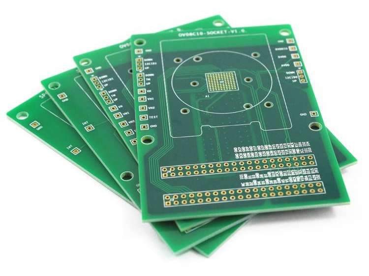
2. Preparing the Base Material
PCB fabrication manufacturers begin with the selection of suitable materials. Most circuit boards use fiberglass-reinforced epoxy (FR4) as the base material: this gives great mechanical strength and heat resistance.
Copper is laminated to the substrate in order to create a path for the flowing current. Thickness will depend on the requirements defined for the board.
3. Print the Circuit Pattern
The next step entails printing the circuit pattern onto the board, whereby an ultra-thin photosensitive film covers the copper layer, and the design is exposed via ultraviolet (UV) light. The design can be said to be a negative mask; hence the film getter waxe from the other places remains stuck, and the copper is then to be removed from this using etching. In this way, only the required area with the copper conductive pattern is retained.
The unnecessary copper is etched away, leaving behind the conductive traces, thus making sure that the boards follow the design specifications reliably.
4. Drilling and Plating
Next step is precise drilling involving giving pilot holes to the pieces of equipment that require joining each other and the electrical connection with layers. These holes, or vias, are then plated with conductive material to connect signals through different layers on the board.
It becomes increasingly important for a multilayer PCB to ensure swift interconnections within the different parts of the Complete Integrated Circuit (CIC).
5. Solder Mask Application
A solder mask protects the copper traces from oxidation and shorting. This layer is often green, although some manufacturers opt for blue, red, or black.
It provides protection against various different accidental damage to the PCB like plus helps introduce a more competitive advantage to the mass production market.
6. Silkscreen Application
Silk-screen printing layers are used for writing labels, components symbols, and identifiers on the PCB. This helps the technicians in assembling and troubleshooting the board.
Generally, white is used as the preferred silkscreen color, although other options exist according to design preferences.
7. Surface Finish
Surface finishes provide for better conductivity and protect the copper pads. The selection depends on price, reliability, and environmental considerations.
8. Electrical Testing
Electrical testing is done to check connectivity and performance before the board goes for assembly. Automated test equipment checks for the presence of short circuiting, open connection, and so forth.
Testing is one of the procedures that allow certain qualifications for each PCB before being put to the large production.
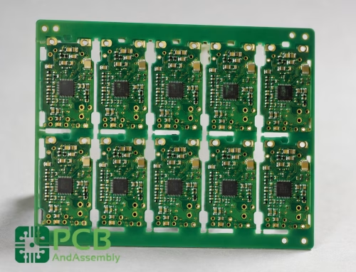
9. Cutting and Packaging
The final step is to separate the individual PCBs from the manufacturing panel. Clean, visually inspected, and ready for transport, the printed circuit boards prepare the boards for assembly in mounting and soldering electronic components.
Defining the Three Main Board Types
Selecting the appropriate board architecture determines both your fabrication complexity and your final production costs. The physical structure of your substrate must support your electrical routing density and signal speed requirements.
Single-Sided PCBs
Single-sided PCBs provide a highly cost-effective substrate option containing only a single conductive copper layer on a rigid base.
- Features a simple manufacturing cycle with minimal processing steps.
- Utilizes low-density routing paths suitable for basic electrical connections.
- Requires no complex interlayer plating or blind via drilling.
Best for: High -volume production of simple consumer electronics like calculators and basic household appliances.
Key limitation: Very restricted routing space makes it impossible to implement high-speed digital signals or dense component matrices.
Double- Sided PCBs
Double-sided boards incorporate conductive copper layers on both sides of the insulating substrate, connected by plated through- holes.
- Allows component placement on both the top and bottom surfaces.
- Supports higher routing density through interconnected copper vias.
- Maintains moderate production costs while offering superior layout flexibility.
When to use: Intermediate designs such as industrial power supplies, automotive sensors, and control systems.
Watch out for: Increased design complexity requires careful attention to trace clearances and via placement to prevent electrical shorts.
Multilayer PCBs
Multilayer designs stack multiple double- sided boards together with insulating prepreg layers under high temperature and pressure.
- Supports complex internal routing planes for dedicated power and ground distribution.
- Enables high-speed signal routing with controlled impedance requirements .
- Integrates advanced via structures including blind and buried vias.
Best for: High-performance computing, aerospace systems, and high-density mobile devices.
Key limitation: Significantly higher fabrication costs and longer lead times due to multiple lamination cycles.
Core Phases of Bare Board Fabrication
The journey from digital Gerber files to a physical copper-clad board involves highly controlled chemical and mechanical steps. Each phase of bare board fabrication demands meticulous process control to prevent microscopic defects from ruining electrical continuity.
Fabrication shops convert your design layouts into physical layers through high-precision photolithography and material lamination. The following table provides a comprehensive overview of the fundamental mechanical and chemical steps required to construct a bare circuit board.
| Fabrication Phase | Process Mechanism | Key Mechanical or Chemical Failure Mode |
| 1. Gerber Verification & DFM | Software-based checks analyze the layout files for clearance violations and manufacturing limits. | Undetected acid traps, narrow trace spacing, or undersized annular rings. |
| 2. Photoimaging & LDI | Laser Direct Imaging patterns photoresist on copper-clad laminates using digital UV exposure. | Improper exposure causing trace width variations or broken signal lines. |
| 3. Inner Layer Etching | Chemical baths dissolve unexposed copper to form the designated circuit patterns. | Over-etching which thins copper traces , or under-etching causing electrical shorts. |
| 4. Multi- Layer Lamination | Prepreg and copper layers are fused using high-pressure hydraulic presses and high-temperature ovens. | Delamination of inner layers caused by moisture entrapment or insufficient press pressure. |
| 5. Drilling & Plating | Computer-controlled drills create vias, which are then electroplated with copper to connect layers. | Rough drill walls leading to plating voids or cracked via barrels during thermal expansion. |
| 6. Solder Mask Application | A protective liquid photoimageable polymer is coated over the outer copper layers and cured. | Mis registered mask layers exposing adjacent traces, leading to solder bridging during assembly. |
| 7. Surface Finish Placement | Exposed copper pads receive protective coatings like Electroless Nickel Immersion Gold (ENIG) or HASL. | Uneven finish thickness causing planarity issues during subsequent surface mount placement. |
The Function of a PCB Manufacturer
A PCB manufacturer plays an integral part in the electronics industry. They must ensure everything from the workstation will comply with extremely fine aspects of quality to efficient passthrough.
Manufacturers invest in such modern equipment and professionals to create the most reliable PCBs in the field. Automation really takes higher grounds in productivity by greatly being instrumental in eliminating errors and subsequently in delivering the greatest of PCBs for nearly any usage.
Common Fabrication Pitfalls and Failure Modes
High-speed manufacturing exposes subtle layout vulnerabilities that rarely cause issues during low-volume prototyping. These physical anomalies typically originate from minor discrepancies in Gerber files or chemical imbalances in the plating baths.
During a 10,000-unit production run of industrial telematics boards, I traced intermittent RF dropouts to an uncalibrated micro-via drilling depth that fractured under thermal expansion. This field failure cost thousands of dollars in warranty replacements and taught me the value of destructive cross-sectional testing .
Understanding common defects allows hardware designers to modify their design rules to eliminate chemical and physical bottlenecks . The list below highlights the most frequent fabrication failures encountered during high-volume production runs:
- Acid traps occur when copper traces meet at acute angles, catching corrosive chemicals during etching and slowly degrading the signal path.
- Copper slivers detach from thin traces during wet processing, floating across the board surface and creating unpredictable electrical shorts.
- Resist starvation happens when dry film photoresist fails to adhere to deep copper grooves, leading to unintentional etching of signal traces.
- Drill runout causes misalignment between multilayer vias, reducing the copper annular ring below minimum IPC limits and breaking electrical connectivity.
Proactively modifying your design rules protects your circuit layout against these chemical and mechanical anomalies.
Challenges in PCB Fabrication
Even in the light of technological advancements, numerous more challenges remain with manufacturers.
• Need for a High Degree of Precision- Ultra-fine traces and small components are now the common requirements of modern electronics, rendering the fabrication of PCBs harder.
• Raw Material Costs- The costs of raw materials such as copper and specialty substrates may reduce profit margins on the PCBs being produced.
• Supply Chain Problems- Component shortages and disruptions to the global supply chain may affect production timelines.
Looking Ahead
The future of PCB fabrication appears to be brilliant with technological advancements. With the growing trends comprising AI-enabled manufacturing, 3D printing for PCBs, and consuming circuit boards, the industry will enter newer markets.
Manufacturers have to adapt to the new demand with unchanged quality and efficiency. Through innovation, the industry can support the rapidly growing electronics market.
FAQ
1) How does copper weight affect the physical design of high-power PCBs?
Thicker copper weights, such as two-ounce or three-ounce copper, handle higher electrical currents but require wider trace spacing to prevent under-cutting during chemical etching.
2) Why is ENIG preferred over HASL for fine-pitch surface-mount components?
Electroless Nickel Immersion Gold provides a perfectly flat, planar surface that prevents component tilting , whereas Hot Air Solder Leveling leaves uneven solder mounds.
3) What is the purpose of conducting a Design for Manufacturability review?
A DFM review identifies potential production errors like acid traps, narrow clearances, and undersized annular rings before fabrication begins.
4) What is the difference between blind vias and buried vias in multilayer boards?
Blind vias connect an outer layer to an inner layer without penetrating the entire board, while buried vias connect internal layers without touching either outer surface.
Wrapping Up
Fabrication of PCBs is one of the very important parts of the entire electronics manufacturing process, governed by highly precise operations from designing to making. Whether fabricating rigid or flexible PCB, manufacturers have to be ensured of reliability and quality.
Increased demand for advanced electronics will push the evolution of fabrication techniques. By remaining ahead of technological advancement, the industry will keep on providing truly cutting-edge solutions in various applications.

Get Quote Free