SMD Resistor Codes Guide: 3-Digit, 4-Digit & EIA-96 Decoded
Unlock the secrets of SMD resistor codes! Learn 3-digit, 4-digit, and EIA -96 systems with this comprehensive guide. Accurately identify components now.
Get Your PCB Quote!

Table of Contents
- 1. Pendahuluan: Mengapa Kode Resistor SMD Penting
- Ringkasan Utama
- 2. Memahami Dasar-Dasarnya: Mengapa Kode, Bukan Pita Warna?
- 3. Sistem Kode Resistor SMD 3 Digit
- 4. Sistem Kode Resistor SMD 4 Digit
- 5. Presisi dan Toleransi: Standar EIA-96
- 6. Penandaan Khusus Resistor SMD
- 7. Kode Huruf Toleransi Resistor
- 8. Resistor SMD Tanpa Label: Kemasan Ultra-Miniatur
- 9. Peringkat Daya dan Ukuran Kemasan
- 10. Kesalahan Interpretasi Umum dan Praktik Terbaik
- 11. FAQ
- 12. Ringkasan
1. Introduction: Why SMD Resistor Codes Matter
In the intricate world of modern electronics, Surface Mount Device (SMD) resistors are ubiquitous. These tiny electronic components are fundamental to the functionality of virtually every Printed Circuit Board (PCB) today. From smartphones to sophisticated industrial controls, their compact form factor and reliability make them indispensable. However, unlike their larger, through-hole counterparts that use intuitive color bands, SMD resistors rely on numerical codes for identification. Understanding these SMD resistor codes is not merely a technicality; it’s an essential skill for anyone involved in electronics.
Mastering SMD resistor codes will significantly enhance your efficiency and accuracy. For quick lookups, try our SMD Resistor Code Calculator.
Key Takeaways
- SMD resistor codes are essential for identifying electronic components in compact, surface-mount designs.
- Distinguish between 3-digit (e.g., 102), 4-digit (e.g., 4701), and EIA-96 (e.g., 47C) codes based on their structure.
- The ‘R’ in codes like ‘4R7′ or ’10R0’ denotes a decimal point, crucial for precise value identification.
- Zero-ohm resistors are marked with ‘0’, ‘000’, or ‘0000’ and act as jumpers or fuses.
- Always use magnification and cross-reference with documentation (like BOMs) to avoid misreading, especially for critical circuit performance.
2. Understanding the Basics: Why Codes, Not Color Bands?
The shift from traditional through-hole components to surface-mount technology (SMT) brought with it significant advantages: smaller footprints, higher component density on PCBs, and suitability for automated assembly processes. However, this miniaturization rendered the familiar color band system impractical for resistors. The physical size of SMD resistors is simply too small for legible color bands, making numerical codes the only viable option for identification.
These numerical code systems are designed not just for human readability but also for machine vision systems, which play a crucial role in automated optical inspection (AOI) during manufacturing. The ability of machines to reliably interpret these codes ensures correct component placement and functionality, thereby improving manufacturing yield and product quality. The resistive element inside these tiny components, often made of a thick or thin film on a ceramic substrate, requires an accurate marking system for proper selection and use.
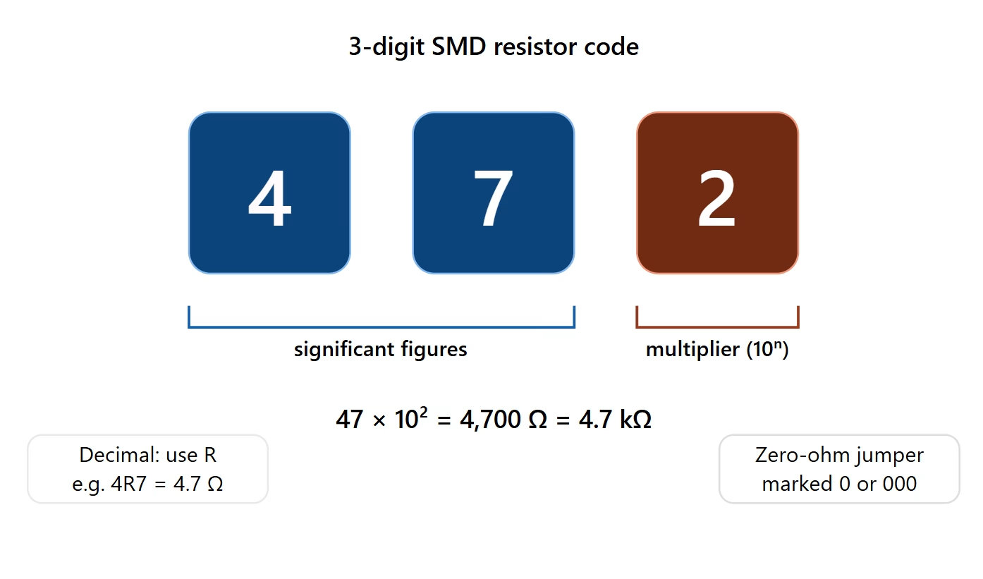
3. The 3-Digit SMD Resistor Code System
The 3-digit system is one of the most common coding methods for SMD resistors, typically used for standard tolerance values (e.g., 5% tolerance). It’s straightforward and easy to interpret once you understand the pattern.
How it Works:
- The first two digits represent the significant figures of the resistance value.
- The third digit is the multiplier, indicating the power of ten by which the significant figures are multiplied.
For example:
- 102means 10 x 102 = 10 x 100 = 1000 Ω or 1 kΩ
- 473means 47 x 103 = 47 x 1000 = 47000 Ω or 47 kΩ
- 220means 22 x 100 = 22 x 1 = 22 Ω
When a decimal point is involved, an “R” is used to indicate its position. The “R” acts as a decimal point, and any trailing digits are significant figures.
- 1R0means 1.0 Ω
- R56means 0.56 Ω
- 4R7means 4.7 Ω
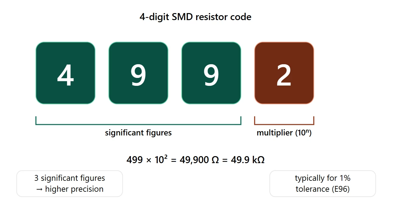
4. The 4-Digit SMD Resistor Code System
The 4-digit system is similar to the 3-digit system but is typically used for resistors with tighter tolerances, such as 1%. It offers higher precision in value representation.
How it Works:
- The first three digits represent the significant figures of the resistance value.
- The fourth digit is the multiplier, indicating the power of ten by which the significant figures are multiplied.
For example:
- 1002means 100 x 10 2 = 100 x 100 = 10000 Ω or 10 kΩ
- 4701means 470 x 101 = 470 x 10 = 4700 Ω or 4.7 kΩ
- 2200means 220 x 100 = 22 0 x 1 = 220 Ω
Similar to the 3-digit system, an “R” is used to denote a decimal point for fractional values.
- 10R0means 10.0 Ω
- 2R20means 2.20 Ω
- R100means 0.1 00 Ω

About PCBAndAssembly
Time is money in your projects – and PCBAndAssembly gets it. PCBAndAssembly is a PCB assembly company that delivers fast, flawless results every time. Our comprehensive PCB assembly services include expert engineering support at every step, ensuring top quality in every board. As a leading PCB assembly manufacturer, we provide a one-stop solution that streamlines your supply chain. Partner with our advanced PCB prototype factory for quick turnarounds and superior results you can trust.
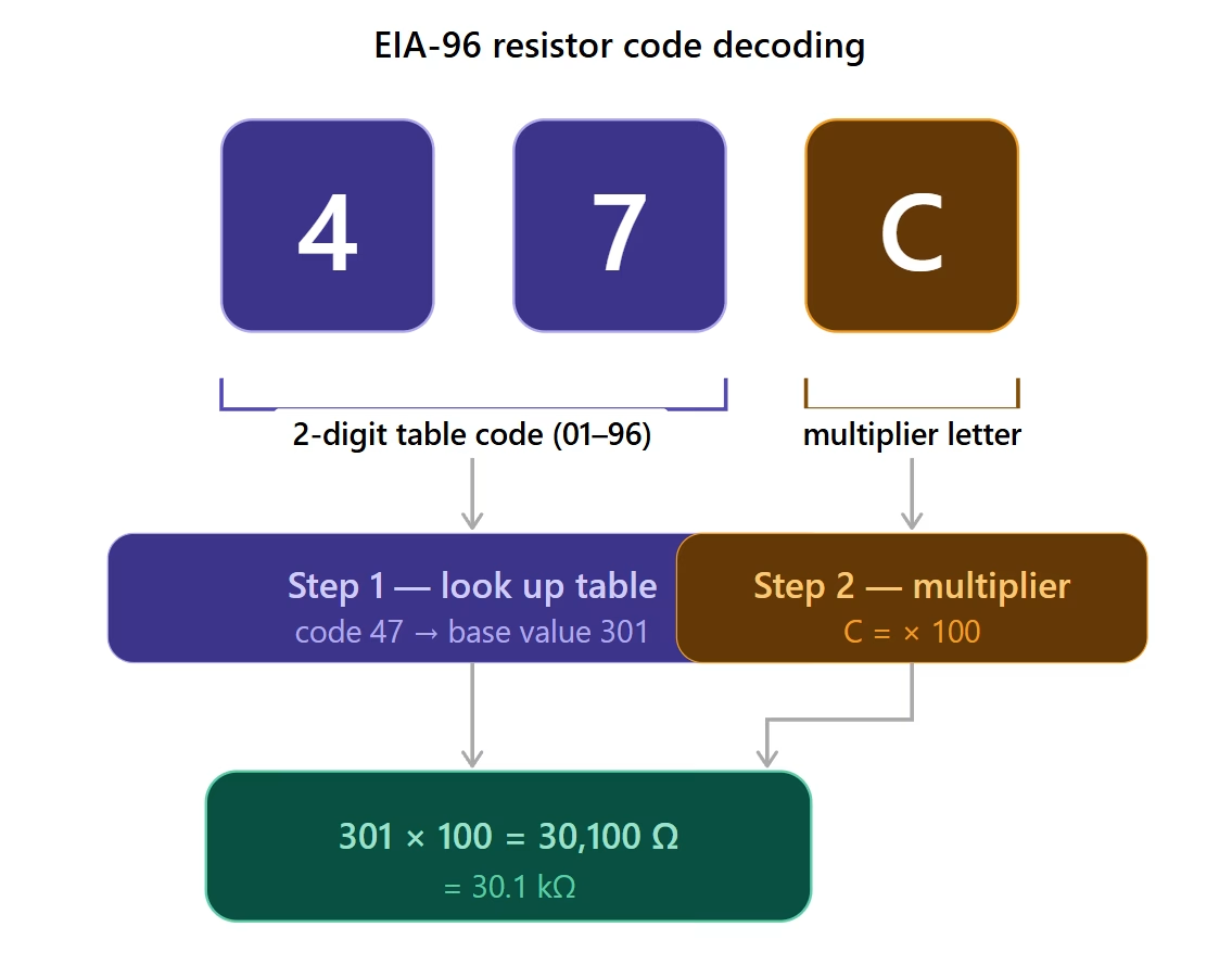
5. Precision and Tolerance: The EIA-96 Standard
For high-precision resistors, often with a 1% tolerance, the EIA-96 standard is widely adopted. This system uses a combination of two numbers and one letter to denote the resistance value. It’s designed to provide a more granular set of standard resistance values.
How it Works:
- The first two digits represent a code from a standardized table, which corresponds to a specific 3-digit significant resistance value.
- The third character (a letter) is the multiplier.
This system requires a lookup table for the two-digit code. Here’s a partial table for the significant values:
| Code | Value | Code | Value | Code | Value | Code | Value |
| 01 | 100 | 25 | 178 | 49 | 316 | 73 | 562 |
| 02 | 102 | 26 | 182 | 50 | 324 | 74 | 576 |
| 03 | 10 5 | 27 | 187 | 51 | 332 | 75 | 590 |
| 04 | 107 | 28 | 191 | 52 | 340 | 76 | 604 |
| 05 | 110 | 29 | 196 | 53 | 348 | 77 | 619 |
| 06 | 113 | 30 | 200 | 54 | 357 | 78 | 634 |
| 07 | 115 | 31 | 205 | 55 | 365 | 79 | 649 |
| 08 | 1 18 | 32 | 210 | 56 | 374 | 80 | 665 |
| 09 | 121 | 33 | 215 | 57 | 383 | 81 | 681 |
| 10 | 124 | 34 | 221 | 58 | 39 2 | 82 | 698 |
| 11 | 127 | 35 | 226 | 59 | 402 | 83 | 715 |
| 12 | 130 | 36 | 232 | 60 | 412 | 84 | 732 |
| 13 | 1 33 | 37 | 237 | 61 | 422 | 85 | 750 |
| 14 | 137 | 38 | 24 3 | 62 | 432 | 86 | 768 |
| 15 | 140 | 39 | 249 | 63 | 442 | 87 | 787 |
| 16 | 143 | 40 | 255 | 64 | 453 | 88 | 806 |
| 17 | 147 | 41 | 261 | 65 | 464 | 89 | 825 |
| 18 | 150 | 42 | 267 | 66 | 475 | 90 | 845 |
| 19 | 154 | 43 | 274 | 67 | 487 | 91 | 866 |
| 20 | 158 | 44 | 280 | 68 | 499 | 92 | 887 |
| 21 | 162 | 45 | 287 | 69 | 511 | 93 | 909 |
| 22 | 165 | 46 | 294 | 70 | 523 | 94 | 931 |
| 2 3 | 169 | 47 | 301 | 71 | 536 | 95 | 953 |
| 24 | 174 | 48 | 309 | 72 | 549 | 96 | 976 |
And here’s the multiplier table for the letter codes:
| Letter | Multiplier |
| F | x 0.01 (10-2) |
| D | x 0.1 ( 10-1) |
| A | x 1 (100) |
| B | x 10 (101) |
| C | x 100 (102) |
| E | x 1000 (103) |
| H | x 10000 (104) |
| X | x 0.001 (10-3) |
| Y | x 0 .001 (10-3) |
| S | x 0.001 (10-3) |
| R | x 0 .001 (10-3) |
| M | x 1,000,000 (106) |
For example:
- 01A: Code “01” is 100. Letter “A” is x1. So, 100 x 1 = 100 Ω.
- 47C: Code “47” is 301. Letter “C” is x100. So, 301 x 100 = 30100 Ω or 30.1 kΩ.
- 96X: Code “96” is 976. Letter “X” is x0.001 . So, 976 x 0.001 = 0.976 Ω.
6. Special SMD Resistor Markings
Beyond the standard numerical codes, some special markings are used for particular types of SMD resistors. Being aware of these can prevent misidentification and ensure correct circuit performance.
- Zero-Ohm Resistors:These components appear as resistors but function as a jumper wire, providing effectively zero resistance. They are typically marked with a single “0”, “000”, or “0000”. They are useful for routing signals across traces on a PCB, acting as fuses, or allowing for optional circuit configurations during prototyping.
- Decimal Point ‘R’, ‘K’, ‘M’:As mentioned, ‘R’ indicates a decimal point for values less than 1 000 Ω. For larger values, ‘K’ signifies kilo-ohms (1000 Ω) and ‘M’ signifies mega-ohms (1,000,000 Ω). The letter can also act as a decimal point.
- 1K0means 1.0 kΩ (1000 Ω)
- 4M7means 4.7 MΩ (4, 700,000 Ω)
- 2K2means 2.2 kΩ (2200 Ω)
7. Resistor Tolerance Letter Codes
While the number of digits in a code often implies the tolerance class, some resistors — particularly on larger packages such as 0603 and above — include an explicit tolerance letter appended to the numerical code. This letter removes ambiguity and directly states the component’s tolerance specification.
Common examples: a resistor marked 103J represents 10 kΩ with 5% tolerance, while 1001F represents 1.00 kΩ with 1% tolerance. The most commonly encountered tolerance letter codes are listed below:
- B— ±0.1%
- C— ±0.25%
- D— ±0.5%
- F— ±1%
- G— ±2%
- J— ±5%
- K— ±10%
Important note: Do not confuse the tolerance letter F (±1%) with the EIA-96 multiplier letter F (×0.01). These letters belong to entirely different systems and must be interpreted based on context. If the code follows the ##L EIA-96 format (two digits plus a letter), the letter is a multiplier. If the letter is appended after a 3-digit or 4-digit numerical code, it denotes tolerance.
8. Unmarked SMD Resistors: Ultra-Miniature Packages
As component packages shrink below the 0402 size threshold, printed markings become physically impossible to apply with reliable legibility. Resistors in 0201 (0.6 mm × 0.3 mm) and 01005 packages are typically shipped completely unmarked. This is not a defect — it is an inherent consequence of the extreme miniaturization demanded by modern high-density PCB designs.
For these unmarked components, the only reliable identification methods are:
- Bill of Materials (BOM) reference— The BOM and pick-and-place data contain the definitive component specifications tied to board coordinates. This is the primary source of truth.
- Feeder position mapping— In automated SMT assembly, the feeder slot number and its verified component value are correlated before production begins. Rigorous feeder mapping protocols prevent loading errors.
- Incoming inspection with LCR meters— Sample-testing resistance values with a calibrated LCR meter on each production lot before releasing components to the assembly line catches labeling errors and shipping mistakes before they cause downstream defects.
When reworking or repairing boards with unmarked resistors, never assume a value based on board position alone. Always consult the schematic or BOM, and verify with a meter by desoldeing one leg of the component to remove parallel circuit paths from the measurement.
9. Power Rating and Package Size
A critical point often overlooked: the SMD resistor code — whether 3-digit, 4-digit, or EIA-96 — only encodes resistance value and tolerance. The power rating is not encoded in the marking at all. It is determined entirely by the physical package size of the component.
Typical power ratings by package size:
- 0201 package— typically 1/20 W (50 mW)
- 0402 package— typically 1/16 W (63 mW)
- 0603 package— typically 1/10 W (100 mW)
- 0805 package— typically 1/8 W (125 mW)
- 1206 package— typically 1/4 W (250 mW)
When designing circuits, always calculate worst-case power dissipation using P = I²R (or P = V²/R) and select a package with a power rating that includes adequate derating margin — typically at least 50% of rated power at maximum operating temperature. Choosing a package purely based on resistance value while ignoring the thermal load is a common design mistake that leads to resistor drift, solder joint degradation, and eventual failure.
Need PCB Manufacturing or Assembly?
Get a free quote within 24 hours. We specialize in prototype-to-production PCB/PCBA for hardware teams worldwide.
10. Common Interpretation Errors and Best Practices
Misreading an SMD resistor code can lead to significant issues, from a non-functional circuit to catastrophic component failure. Here are common pitfalls and best practices for accurate identification:
- Confusing 3-Digit and 4-Digit Codes:A common mistake is applying the 3-digit rule to a 4-digit code or vice versa. Always check the number of digits before interpreting. The context (e.g., tolerance requirements, adjacent components) can often give clues.
- Misinterpreting “R” as a Multiplier:Remember, “R” indicates a decimal point, not a multiplier (unless it’s part of the EIA-96 system’s specific letter codes, which is less common for decimal placement in other systems).
- Overlooking Special Markings:A resistor marked “000” is not 0 ohms * 10^0 = 0 ohms; it’s specifically a zero-ohm link. Always be mindful of these unique identifiers.
- Environmental Factors:Over time, markings can fade or become obscured due to heat, chemicals, or physical abrasion. When in doubt, consulting the circuit’s bill of materials (BOM) or schematic is the most reliable approach.
- Using Magnification:Due to their tiny size, a magnifying glass or microscope is often necessary for clear reading, especially with smaller package sizes. This is crucial for avoiding errors during incoming quality control or rework .
- Cross-Referencing:If possible, cross-reference the marking with the manufacturer’s datasheet or a reliable SMD resistor code chart, particularly for EIA-96 codes or less common component types.
Adhering to these best practices will significantly improve your accuracy when working with surface mount resistors, safeguarding your projects from costly mistakes and ensuring optimal electronic component functionality.
PCBAndAssembly PCBA service ensures every component in your BOM—from basic SMD resistors to complex ICs—is placed with the correct value, footprint, and orientation, supported by a large in-stock component library. This reduces manual verification effort, minimizes rework risk, and helps bring your design from prototype to production with greater confidence.
11. FAQ
Question:Why do SMD resistors use codes instead of color bands like through-hole resistors?
Answer: SMD resistors are much smaller than through-hole resistors, making color bands impractical and difficult to read. Numerical codes are compact and can be easily read by both humans (with magnification) and automated optical inspection systems during SMT assembly, which is crucial for modern electronic components.
Question:How can I tell if an SMD resistor uses the 3-digit, 4-digit, or EIA-96 system?
Answer: The 3-digit and 4-digit systems are identified by having three or four numbers respectively (e.g., 102, 4701). The EIA-96 system is distinct because it uses two numbers followed by a letter (e.g., 01A, 47C). If you see a letter as the third character, it’s almost certainly EIA-96.
Question:What does an “R” in an SMD resistor code mean?
Answer: In 3-digit and 4-digit codes, “R” typically signifies a decimal point. For example, “4 R7” means 4.7 ohms, and “R100” means 0.100 ohms. In the EIA-96 system, “R” is sometimes used as a multiplier letter, often indicating a very small multiplier (e.g., x 0.001), but its primary role in general codes is as a decimal point.
Question:Does the body color of an SMD resistor (black vs. blue/green) carry any meaning?
Answer:The vast majority of standard chip resistors are black with a light protective overglaze. Colors such as blue or green sometimes indicate a special type — such as a high-precision thin-film resistor or a specialty product — but this is not standardized across manufacturers. Always rely on the printed code and the datasheet, not the body color, for identification.
Question:Does the SMD resistor code tell me the power rating?
Answer: The code only encodes resistance value and, in some cases, tolerance. The power rating is determined entirely by the physical package size. For example, a 0402 package typically handles 1/16 W, while an 0805 package handles 1/8 W. Selecting the wrong package for the power dissipation requirements of your circuit can cause overheating and component failure. Always calculate P = I²R and choose the package accordingly.
Question:I see a component marked 102 but it has 8 pins. What is it?
Answer:That is almost certainly an SMD resistor array or resistor network. The code (102 = 1 kΩ) typically applies to all the individual resistors inside the single package. These components are used to save board space, for example for pull-up or pull-down resistors on a data bus. The array may be “isolated” (each resistor fully independent, e.g., four 1 kΩ resistors sharing an 8-pin package) or “bussed” (one common pin shared by all resistors). Check the schematic to determine which configuration applies.
Question:My EIA-96 code looks ambiguous when rotated — could I be reading it upside-down?
Answer:Yes, this is a real issue. A code like “06” can look like “90” when flipped. Some manufacturers address this by printing a small underline or orientation bar beneath the code. If no such mark is present and the orientation is genuinely ambiguous, use a multimeter to measure the resistance directly rather than guessing. Never assume orientation on a component that could be misread — a wrong value in a critical circuit path can cause immediate or latent failures.
12. Summary
Understanding SMD resistor codes is fundamental for anyone working with modern electronics. Due to their compact size, surface mount devices employ numerical marking systems rather than color bands. This guide covered the three primary systems: the 3-digit code (two significant figures, one multiplier), the 4-digit code (three significant figures, one multiplier, often for 1% tolerance), and the EIA-96 standard (a two-digit value code and a letter multiplier, used for high-precision 1% tolerance resistors). Special markings like ‘R’ for decimal points, and ‘000’ for zero-ohm resistors, are also crucial. Accurate interpretation, often aided by magnification and cross-referencing with documentation like the bill of materials, prevents errors, ensures proper circuit performance, and supports efficient SMT assembly.

Get Quote Free