Rogers RO4835 Laminates: Complete Guide to 77 GHz Automotive Radar and 5G PCB Materials
Rogers RO4835 laminate guide for 77 GHz automotive radar and 5G PCBs. Dk/Df specs, oxidation resistance, LoPro copper, and FR-4-compatible fabrication.
Get Your PCB Quote!
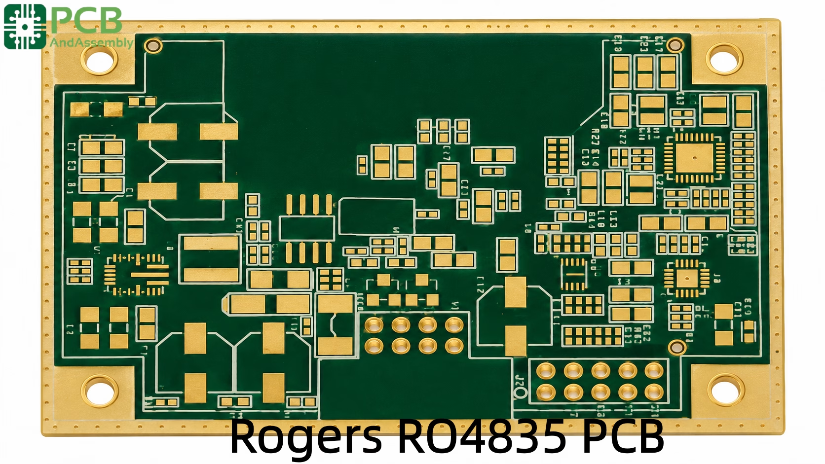
Table of Contents
- 1. What Are RO4835IND LoPro Laminates?
- 2. Electrical Performance: Dielectric Constant and Loss
- 3. Oxidation Resistance: The RO4835 Differentiator
- 4. Mechanical and Thermal Properties
- 5. Manufacturing and Fabrication Compatibility
- 6. RO4835 vs. RO4350B: A Comparative Analysis
- 7. LoPro Copper Technology in RO4835
- 8. Hybrid Stackups and Design Best Practices
- 9. Critical Applications: 77 GHz Radar and 5G
- 10. Frequently Asked Questions
- 11. Summary
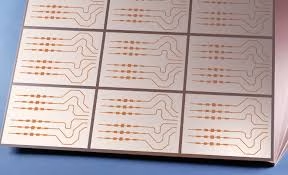
1. What Are RO4835IND LoPro Laminates?
Rogers RO4835 is a high-frequency, thermoset hydrocarbon ceramic-filled laminate specifically engineered for applications requiring superior oxidation resistance and high-temperature stability. As a member of the RO4000 series, it fills the performance gap between low-cost FR-4 materials and high-performance PTFE (Polytetrafluoroethylene) substrates. While many microwave laminates degrade when exposed to elevated temperatures over long durations, RO4835 preserves its dielectric integrity through a proprietary antioxidant additive system built into the resin.
High-frequency RF circuits operating in automotive or industrial settings face a specific failure mode: thermal-oxidative degradation. In traditional thermoset laminates, prolonged heat exposure drives an oxidation reaction that raises the dissipation factor (Df) and shifts the dielectric constant (Dk). For a 77 GHz radar sensor or a 5G power amplifier, these shifts produce measurable signal attenuation, phase errors, and eventual hardware failure. RO4835 was engineered to interrupt this degradation pathway.
The material is IPC-4103 compliant and designed to meet the rigorous demands of automotive radar, phased array antennas, and power amplifiers. Unlike PTFE-based substrates that require specialized sodium naphthenate treatment or plasma etching for through-hole preparation, RO4835 is fully compatible with standard epoxy/glass (FR-4) fabrication processes. This compatibility substantially reduces the total cost of ownership for RF designs by enabling high-volume production on existing manufacturing lines.
Need PCB Manufacturing or Assembly?
Get a free quote within 24 hours. We specialize in prototype-to-production PCB/PCBA for hardware teams worldwide.
2. Electrical Performance: Dielectric Constant and Loss
The predictability of a PCB substrate is what determines whether a simulated design translates faithfully to a functional physical board. In high-frequency design, signal velocity and impedance are fundamentally governed by the dielectric constant (Dk). RO4835 is a hydrocarbon ceramic-filled laminate that maintains a highly stable Dk across a wide frequency range.
Its process Dk is specified at 3.48 ± 0.05 at 10 GHz. This is the value measured using IPC standards to verify material consistency. For circuit modeling and simulation, however, engineers use a design Dk of 3.66, which reflects the material’s actual in-circuit behavior and remains stable across 8 GHz to 40 GHz. Designers must appreciate this distinction: relying on the process Dk during simulation can cause antenna resonant frequencies to shift in the fabricated board. The design Dk is the correct input for impedance calculators and electromagnetic simulation tools such as Ansys HFSS or Keysight ADS.
The dissipation factor (Df), or tan delta, is 0.0037 at 10 GHz. While higher than ultra-low-loss PTFE materials (which can reach as low as 0.0009), this Df is more than adequate for automotive radar and wireless infrastructure applications where trace lengths are relatively short. Signal integrity at millimeter-wave frequencies is sensitive to any dielectric heating and energy absorption, and RO4835 keeps both effects minimal.
Dielectric Stability Across Frequencies
Many substrates exhibit Dk dispersion — a shift in dielectric constant as frequency increases — that complicates broadband designs. RO4835 presents a flat Dk profile compared to standard FR-4, which can experience Dk swings severe enough to disrupt high-speed digital and RF signals. This flatness supports wide-bandwidth applications where the substrate must underpin a broad spectrum without introducing timing jitter or impedance mismatches.
An additional parameter worth noting is the Thermal Coefficient of Dk (TCDk), measured at +50 ppm/°C across −50 °C to 150 °C. This low TCDk ensures that impedance remains consistent as the device heats up during operation — a critical requirement for engine-compartment electronics and outdoor 5G infrastructure that must perform across extreme temperature excursions.
| Property | Value | Frequency / Condition |
| Dielectric Constant (Dk) – Process | 3.48 ± 0.05 | 10 GHz / 23 °C |
| Dielectric Constant (Dk) – Design | 3.66 | 8 GHz to 40 GHz |
| Dissipation Factor (Df) | 0.0037 | 10 GHz / 23 °C |
| Dielectric Thermal Coefficient (TCDk) | +50 ppm/°C | −50 °C to 150 °C |
| Volume Resistivity | 10⁶ MΩ·cm | ASTM D257 |
Table 1: Electrical Specifications of RO4835
3. Oxidation Resistance: The RO4835 Differentiator
The most significant technical advancement that RO4835 introduces over its predecessor, RO4350B, is substantially improved resistance to oxidation. Oxidation in hydrocarbon laminates occurs when the resin system reacts with oxygen at elevated temperatures, causing progressive brittleness and a rise in Df. This is a cumulative effect — inconsequential in the short term but increasingly significant over years of service.
In applications such as automotive ADAS, where a vehicle may remain in service for 15 years or more, the total thermal exposure can be substantial. RO4835 incorporates a proprietary antioxidant system that interrupts this degradation pathway, delivering a tenfold improvement in oxidation resistance compared to conventional thermoset formulations. Testing demonstrates that the material maintains its original electrical properties even after thousands of hours of thermal aging at 150 °C.
This resistance also benefits the fabrication process. The material can withstand multiple lead-free reflow cycles without risking delamination or copper bond degradation, which is a meaningful advantage in high-mix, high-reliability manufacturing environments. The copper-to-dielectric bond strength remains high throughout the assembly process, ensuring that pad lifting and via-barrel separation remain non-issues even in demanding thermal profiles.
4. Mechanical and Thermal Properties
Beyond electrical specifications, the mechanical reliability of a PCB substrate determines its service life in harsh environments. RO4835 features a glass transition temperature (Tg) exceeding 280 °C and a decomposition temperature (Td) of 390 °C. These values confirm that the material remains mechanically stable throughout the 260 °C peaks of lead-free soldering processes without any loss of structural integrity.
Coefficient of Thermal Expansion (CTE)
The reliability of plated through-holes (PTH) and blind vias depends heavily on CTE alignment between the substrate and the copper conductors. If the Z-axis CTE of the laminate significantly exceeds that of copper (approximately 17 ppm/°C), repeated thermal cycling will fatigue and eventually crack the via barrels. RO4835 features a Z-axis CTE of 46 ppm/°C — well-matched to copper — ensuring that PTH connections remain structurally sound under severe thermal shock. The X-axis and Y-axis CTEs are 13 and 15 ppm/°C respectively, contributing to excellent in-plane dimensional stability during lamination.
Moisture Absorption and Dimensional Stability
RO4835 exhibits a moisture absorption rate of just 0.06% (ASTM D570). For context, typical FR-4 absorbs between 0.10% and 0.20%. This low uptake matters for two reasons: high moisture levels increase signal loss, and moisture trapped within the substrate can vaporize explosively during reflow soldering — a phenomenon known as popcorning. RO4835 stays dimensionally dry and stable, contributing to higher assembly yields in humid manufacturing environments and maintaining electrical performance in outdoor deployments exposed to fluctuating humidity.
Dimensional stability in the X–Y plane is typically better than 0.5 mm/m, which is essential for the precise registration of high-density multilayer boards. If the material shifts during lamination or drilling, the resulting misalignment creates shorts, broken circuits, or via-to-pad registration failures.
| Property | Value | Unit / Test Method |
| Glass Transition Temperature (Tg) | > 280 | °C (DSC) |
| Decomposition Temperature (Td) | 390 | °C (TGA) |
| CTE – X-axis | 13 | ppm/°C |
| CTE – Y-axis | 15 | ppm/°C |
| CTE – Z-axis | 46 | ppm/°C |
| Thermal Conductivity | 0.69 | W/m/K at 80 °C |
| Moisture Absorption | 0.06 | % (ASTM D570) |
Table 2: Mechanical and Thermal Specifications of RO4835
5. Manufacturing and Fabrication Compatibility
A primary driver for selecting RO4835 is its FR-4-like processability. Designers can deploy a high-frequency laminate without the elevated fabrication costs associated with PTFE. The material can be processed using standard carbide drills, though the ceramic filler accelerates tool wear compared to standard FR-4. Reducing drill hit counts per bit and using hard-coated tooling with optimized feed/speed rates extends tool life and preserves hole-wall quality. Excessive heat during drilling can cause smear, though RO4835 is more resistant to this than pure resin systems.
Like all thin laminates used in multilayer builds, RO4835 should be baked before processing to relieve residual stress and remove absorbed moisture.
Desmear and Plating
RO4835 supports standard chemical desmear processes using permanganate. This eliminates the need for plasma etching — a costly and time-consuming step required for PTFE substrates. The resin system promotes strong adhesion for electroless copper plating, ensuring reliable interconnects in multilayer designs.
Surface Finish Selection
The choice of surface finish has a measurable impact on insertion loss at millimeter-wave frequencies. ENIG (Electroless Nickel Immersion Gold) is widely used but introduces loss at high frequencies because of the nickel layer’s magnetic properties. For designs operating at 77 GHz, Immersion Silver or OSP (Organic Solderability Preservative) are generally preferred to minimize insertion loss in the signal path. ENEPIG is a viable alternative that retains wire-bonding capability while reducing the nickel contribution. RO4835 is compatible with all of these finishes.
| Feature | Rogers RO4835 | PTFE-Based Material |
| Manufacturing Process | Standard FR-4 Compatible | Requires Specialized Processes |
| Drilling | Carbide Drills (Standard) | Specialized Bits / Settings |
| Via Preparation | Standard Permanganate Desmear | Plasma or Sodium Naphthenate |
| Mechanical Rigidity | High (Hydrocarbon/Ceramic) | Low (Soft/Ductile) |
| Cost (Fabrication) | Low to Moderate | High |
Table 3: Comparison of RO4835 vs. PTFE-Based Laminates
6. RO4835 vs. RO4350B: A Comparative Analysis
RO4835 is the evolutionary successor to RO4350B for high-reliability environments. Both materials share identical Dk (3.48) and Df (0.0037) values, so a designer migrating from RO4350B to RO4835 requires no changes to the electrical stackup model. The critical difference is long-term environmental behavior. RO4835 was developed specifically to satisfy the demanding automotive safety standards that require hardware to perform reliably over a vehicle’s expected 15-year service life.
In high-power RF applications, the heat generated by active devices can accelerate substrate oxidation. A power amplifier that runs continuously at elevated junction temperatures will stress a conventional thermoset laminate over time. RO4835 addresses this by maintaining its electrical properties through the same thermal conditions that would degrade RO4350B. Additionally, RO4835 offers slightly lower moisture absorption (0.06%), providing better environmental stability in humid deployments.
| Feature | RO4835 | RO4350B | PTFE (RT/duroid) |
| Oxidation Resistance | Excellent (10×) | Standard | N/A (Inert) |
| Processing | Standard FR-4 | Standard FR-4 | Specialized (Plasma) |
| Relative Cost | Moderate | Lower | High |
| Dissipation Factor (Df) | 0.0037 | 0.0037 | ~0.0009 |
| Dk Stability | High | High | Very High |
| Moisture Absorption | 0.06% | ~0.06% | < 0.02% |
Table 4: RO4835 vs. RO4350B vs. PTFE
About PCBAndAssembly
Time is money in your projects – and PCBAndAssembly gets it. PCBAndAssembly is a PCB assembly company that delivers fast, flawless results every time. Our comprehensive PCB assembly services include expert engineering support at every step, ensuring top quality in every board. As a leading PCB assembly manufacturer, we provide a one-stop solution that streamlines your supply chain. Partner with our advanced PCB prototype factory for quick turnarounds and superior results you can trust.
7. LoPro Copper Technology in RO4835
At microwave frequencies, the skin effect concentrates electrical current near the outer surface of the copper conductor. If that surface is rough — as it typically is with standard electro-deposited (ED) copper, where roughness improves mechanical adhesion to the dielectric — the current must traverse the peaks and valleys of the copper topography. This longer effective path increases resistive loss, which shows up directly as insertion loss in the finished circuit.
RO4835 is available with Rogers’ proprietary LoPro (Low Profile) reverse-treated copper foil, which provides a significantly smoother copper-to-dielectric interface without sacrificing bond strength. For designs operating above 20 GHz — and especially for 77 GHz automotive radar — specifying LoPro copper is one of the most effective single-material decisions an engineer can make to improve link budget. The benefits are:
- Reduced Insertion Loss: Smoother copper suppresses the skin-effect path lengthening, cutting conductor loss at mmWave frequencies.
- Improved Phase Stability: Lower and more consistent roughness reduces lot-to-lot phase variation, tightening production tolerances on filters and phase-matched lines.
- Finer Line Resolution: A smoother copper surface improves etch accuracy, which is critical for tightly spaced RF filters, directional couplers, and transmission lines at sub-millimeter wavelengths.
8. Hybrid Stackups and Design Best Practices
Designing with RO4835 requires careful attention to stackup construction and trace geometry. Because the design Dk is 3.66, impedance calculators must be initialized with this value rather than the process Dk of 3.48. Laminate thickness should also be chosen deliberately; RO4835 is available in thicknesses from 0.004″ (4 mil) to 0.060″ (60 mil).
Hybrid Stackup Strategy
To optimize cost without sacrificing RF performance, engineers routinely design hybrid boards where only the signal-critical outer layers use RO4835, while the inner layers — carrying power, ground planes, and low-speed signals — use standard, lower-cost FR-4 such as IT-180 or 370HR. This architecture can dramatically reduce material cost on multilayer designs.
When constructing a hybrid stackup, CTE matching between adjacent materials is important. Significant CTE mismatches can cause warping during lamination. Using a no-flow or low-flow prepreg such as RO4450F to bond the Rogers outer layers to the FR-4 core is standard industry practice; this prevents resin bleed from filling or distorting the microwave structures.
Ground Plane Design
For optimal RF performance, a solid ground plane is mandatory beneath the signal layer. In multilayer designs, the ground plane should be placed on the first inner layer to minimize the distance between the signal trace and its return current path. Closer spacing reduces parasitic inductance, suppresses radiated EMI, and stabilizes characteristic impedance.
Thermal Management
While RO4835 offers better thermal conductivity than FR-4 (0.69 W/m/K vs. approximately 0.25 W/m/K for standard FR-4), high-power components may still require thermal vias or embedded copper coin technology to efficiently extract heat from the device. The material’s high Tg permits the implementation of aggressive thermal solutions during assembly without risk of delamination or pad lifting.
9. Critical Applications: 77 GHz Radar and 5G
The proliferation of Advanced Driver Assistance Systems (ADAS) has made RO4835 a cornerstone of automotive electronics. Adaptive cruise control, automatic emergency braking, and blind-spot detection all rely on 77 GHz radar sensors that must operate reliably for the full vehicle lifetime in extreme thermal and humidity conditions. RO4835 provides the Dk stability, low loss, and oxidation resistance that these systems demand. Its compatibility with standard PCB manufacturing also makes it the practical choice for the high production volumes characteristic of the automotive supply chain.
In the telecommunications sector, 5G small cells and Massive MIMO antenna arrays use RO4835 for power amplifiers and beamforming networks. The material’s thermal conductivity advantage over FR-4 is especially relevant in compact 5G equipment where passive cooling is the only thermal management option. As 5G infrastructure migrates deeper into the mmWave spectrum, the ability to manufacture stable, low-loss substrates at scale becomes a logistical necessity rather than merely a technical preference. RO4835’s low moisture absorption additionally makes it well-suited for outdoor installations subjected to year-round humidity cycles.
10. Frequently Asked Questions
Is RO4835 RoHS compliant?
Yes. RO4835 laminates are fully RoHS compliant and compatible with lead-free assembly processes. With a Tg of 280 °C and a Td of 390 °C, the material withstands multiple lead-free reflow cycles without degradation.
How does RO4835 handle moisture compared to FR-4?
RO4835 absorbs only 0.06% moisture, well below the 0.10%–0.20% typical of FR-4. This lower uptake delivers more stable electrical performance in humid environments and eliminates the risk of popcorning during high-temperature reflow.
Can RO4835 be used in a hybrid stackup with FR-4?
Yes, and this is standard practice. RO4835 handles the outer (RF-critical) layers while cost-effective FR-4 fills the inner layers. Using a compatible low-flow prepreg such as RO4450F ensures a reliable bond without resin migration into microwave structures.
What is the difference between RO4835 and RO4835T?
RO4835T is a thinner variant of the laminate developed for multilayer builds requiring specific dielectric thicknesses for impedance matching in compact layouts. It shares the same oxidation-resistant chemistry.
Does RO4835 require plasma etching for via preparation?
No. Unlike PTFE-based materials, RO4835 is a thermoset that responds to standard chemical (permanganate) desmear. This eliminates both the cost and the specialized equipment associated with plasma processing.
Does RO4835 require special storage?
Like all high-frequency laminates, it should be stored in a cool, dry environment to limit moisture uptake, though its inherently low absorption rate of 0.06% means it is considerably more tolerant of imperfect storage conditions than most alternatives.
What copper weights and foil types are available?
RO4835 is typically supplied with 0.5 oz (18 µm) or 1.0 oz (35 µm) copper foils, with LoPro (low-profile) options available for both weights. LoPro foil is recommended for any design operating above 24 GHz.
11. Summary
Rogers RO4835 represents a targeted evolution in RF laminate technology, addressing the long-term reliability concerns of the automotive and telecommunications industries without imposing the manufacturing complexity of PTFE. Its tenfold improvement in oxidation resistance over conventional thermoset materials guarantees electrical stability across decades of service. FR-4-compatible fabrication keeps costs manageable even in high-volume production runs, and the availability of LoPro copper foil provides a direct path to reduced insertion loss at 77 GHz and beyond.
Engineers designing 77 GHz radar modules, 5G power amplifiers, or any RF system that must survive prolonged thermal stress should evaluate RO4835 as their primary substrate. The combination of stable Dk, low TCDk, robust mechanical properties, and manufacturing accessibility makes it one of the most versatile high-frequency laminates available today.

Get Quote Free