What Are SMT Components? SMD Types, Sizes, and Packages
SMT components are electronic parts mounted directly onto a PCB surface. Common types include resistors, capacitors, inductors, diodes, transistors, and ICs
Get Your PCB Quote!

Table of Contents
You may also encounter the term SMD (Surface Mount Device) — this refers to the individual components themselves, while SMT (Surface Mount Technology) describes the overall assembly process. In practice, “SMT components” and “SMD components” are often used interchangeably in the industry.
Pcbandassembly deals with numerous components suitable for surface mount technology (SMT) when manufacturing or assembling PCBs for customers. This is because almost all electronic products we mass-produce today use SMT components due to their multiple advantages.
1. SMT Component Division
SMT components (Surface Mount Technology components), also known as SMD components (Surface Mount Devices), are electronic parts mounted directly onto the surface of a printed circuit board (PCB) — as opposed to through-hole components, which require leads to be inserted into drilled holes. SMT components are the foundation of modern electronics, enabling the compact, high-density circuit boards found in smartphones, laptops, automotive systems, and medical devices.
Component manufacturers offer SMT components in a variety of packages and standardize the packages so that assemblers can easily use them in automated equipment. SMT components can be divided into two major categories: passive components and active components.

While passive components mostly come in small rectangular packages, some also have cylindrical packages. Although passive SMT components have the most variety, it really depends on the level of interconnect required, the technology used by the manufacturer, and many other factors. However, there are two main factors that determine the type of package a manufacturer uses for SMT components:
• Processing
• Standard
1) SMT Packaging Processing
SMT packages have been developed with component handling in mind. SMT technology aims primarily to facilitate automated PCB assembly. Hence, manufacturers place special attention on to the design of packages that make it easy for Pick-and-place machines to handle them easily during the assembly of printed circuit boards.
Allowing easy component handling ensures the reduction of manufacturing costs while making sure that the quality of final equipment is high, resulting in the highest quality for the assembled PCBs. Ease of handling often allows holding small components loosely in a hopper, feeding them down a tube, and allowing the machine to pick them out as necessary while mounting.
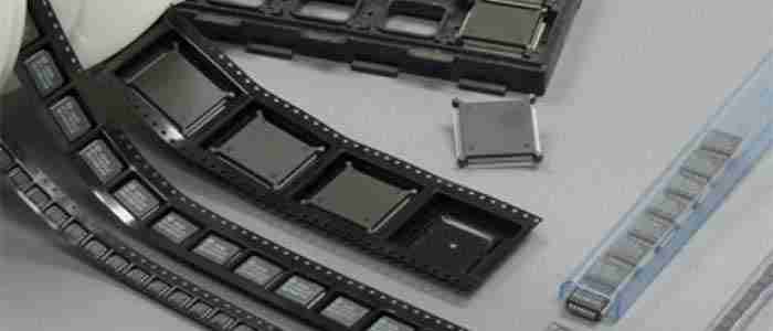
Other larger SMT components, both active and passive, such as resistors, capacitors, diodes, and transistors are available in tapes on reels. The reel usually has tape to hold the components in a line, while a second tape sticks loosely onto the back to retain the components. The pick-and-place machine removes the holding tape as it picks up the component, exposing the next component to be used.
Larger components, such as dual in-line surface mount ICs, are usually packaged in tubes, and the machine removes them one by one from the tube as needed. Gravity forces the next IC to slide off the tube, ready for the next pick.
Larger ICs such as flat packages, QFPs, BGAs, etc. may come in tray or waffle packages. The pick-and-place machine can handle these packages and remove them for mounting as needed.
2) SMT Packaging Standards
Standards provide a great deal of consistency across the industry. Most SMT components are sized to industry standards, such as the JEDEC specification. Although different types of components require different SMT packages, the fact that they conform to standards keeps the design of printed circuit boards simple, as designers can use standard outlines and pad sizes.
In addition, SMT components in standard-sized packages simplify manufacturing for placement machines, which can use standard feedstock to process the components, thus reducing costs. Standards categorize different SMT packages based on component type while retaining standard footprints for each, such as:
• Passive rectangular components
• Tantalum capacitors
• Electrolytic capacitors
• Transistors and diodes
• DIL integrated circuits
• QIL integrated circuits
• Chip-on-board ICS
2. SMT Component Types
1) Passive Rectangular Components
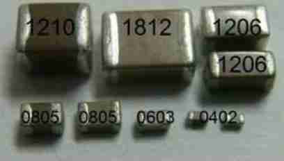
SMT groups mainly include passive resistors, capacitors, and inductors. Technological advances have made it possible to manufacture and use components of increasingly smaller sizes.
| Passive SMD Package Type | Dimension (inches) | Dimension (mm) |
| 2920 | 0.29 x 0.20 | 7.4 x 5.1 |
| 2725 | 0.27 x 0.25 | 6.9 x 6.3 |
| 2512 | 0.25 x 0.125 | 6.3 x 3.2 |
| 2010 | 0.2 x 0.1 | 5.0 x 2.5 |
| 1825 | 0.18 x 0.25 | 4.5 x 6.4 |
| 1812 | 0.18 x 0.125 | 4.6 x 3.0 |
| 1806 | 0.18 x 0.06 | 4.5 x 1.6 |
| 1210 | 0.125 x 0.10 | 3.2 x 2.5 |
| 1206 | 0.12 x 0.06 | 3.0 x 1.5 |
| 1008 | 0.10 x 0.08 | 2.5 x 2.0 |
| 0805 | 0.08 x 0.05 | 2.0 x 1.3 |
| 0603 | 0.06 x 0.03 | 1.5 x 0.8 |
| 0402 | 0.04 x 0.02 | 1.0 x 0.5 |
| 0201 | 0.02 x 0.01 | 0.6 x 0.3 |
| 01005 | 0.016 x 0.008 | 0.4 x 0.2 |
Of the sizes shown above, 0402 and 0603 are the most popular SMD sizes that designers and assemblers use. The 1206 and 1812 sizes are mostly for specialized components requiring higher levels of power dissipation. However, the industry is increasingly moving towards more miniature forms such as 0201 and 01005. Usually, SMD inductors are available in 0603 and 0805 sizes.
2) Tantalum Capacitors

The construction of SMT type tantalum capacitors is different, forcing manufacturers to make them in different sizes than those listed above. The most common tantalum capacitor sizes are:
| Common SMD Tantalum Capacitor Packages | |||
| SMD Package Size | EIA Standard | Dim. (Inches) | Dim. (mm) |
| A | EIA 3216-18 | 0.13 x 0.06 x 0.06 | 3.2 x 1.6 x 1.6 |
| B | EIA 3258-21 | 0.14 x 0.11 x 0.075 | 3.5 x 2.8 x 1.9 |
| C | EIA 6032-20 | 0.24 x 0.13 x 0.87 | 6.0 x 3.2 x 2.2 |
| D | EIA 7343-31 | 0.3 x 0.17 x 0.1 | 7.3 x 4.3 x 2.4 |
| E | EIA 7343-43 | 0.3 x 0.17 x 0.16 | 7.3 x 4.3 x 4.1 |
3) Electrolytic Capacitors
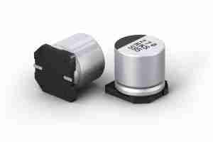
Electrolytic capacitors come in large varieties depending on their capacitance value and their working voltage. The most common sizes are:
| Common SMD Electrolytic Capacitor Packages | ||
| SMD Package Type (Panasonic) | Dimensions (inches) | Dimensions (mm) |
| A | 0.13 x 0.13 | 3.3 x 3.3 |
| B | 0.17 x 0.17 | 4.3 x 4.3 |
| C | 0.2 x 0.2 | 5.3 x 5.3 |
| D | 0.26 x 0.26 | 6.6 x 6.6 |
| E/F | 0.33 x 0.33 | 8.3 x 8.3 |
| G | 0.4 x 0.4 | 10.3 x 10.3 |
| H | 0.53 x 0.53 | 13.5 x 13.5 |
| J | 0.67 x 0.67 | 17.0 x 17.0 |
| K | 0.75 x 0.75 | 19.0 x 19.0 |
4) Transistors & Diodes

Manufacturers offer transistors and diodes in the same type of SMT packages. Although diodes only have two terminals, it is easier to place packages with three terminals. Although manufacturers offer a wide variety of SMT transistors and diodes, the most popular ones are:
| Common SMD Transistor and Diode Packages | |||
| SMD Package Type | Used for | Dim. (inches) | Dim. (mm) |
| SOT-23 | Small Signal Diodes, Transistors, ICs (Op-Amps etc.) | 0.12 x 0.07 x 0.05 | 3.0 x 1.75 x 1.3 |
| SOT-223 | Medium Power Diodes and Transistors | 0.26 x 0.15 x 0.07 | 6.7 x 3.7 x 1.8 |
| DPAK | High Power Diodes and Transistors | 0.25 x 0.09 x 0.4 | 6.5 x 2.25 x 10.2 |
5) DIL Integrated Circuit Packaging
There are many types of DIL ICs available from manufacturers, the most common of which are:
| Common DIL Integrated IC Packages | |||
| SMD Package Type | Pin Type | Pin Spacing (mils) | Pin Spacing (mm) |
| SOIC | Gull-Wing | 50 | 1.27 |
| SSOP | Gull-Wing | 25 | 0.635 |
| TSSOP | Gull-Wing | 25.6 | 0.65 |
| SOJ | J-leaded | 50 | 1.27 |
6) QIL Integrated Circuit Packaging
These are common flat package type ICs for surface mounting. Of the several variations available, the most common are:
√ QFP: This is the most common type of flat package and has many variations like LQFP, PQFP, CQFP, TQFP etc. The pins come out from all four sides and can be either gull-wing or J-type leads.

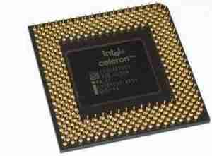
√ PGA: Pin Grid Array packages are usually square with pins coming out of the bottom. The pins may or may not cover the entire bottom surface. Variants include flip chips, staggered pins, and ceramic types. PGA packages offer more interconnects than QFP.
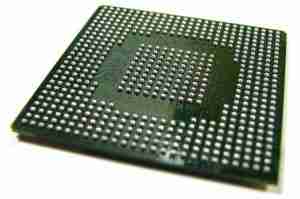
√ BGA: Ball Grid Array is similar to PGA, with solder balls instead of pins, making BGA more robust. BGA provides very high-density interconnects, lower thermal resistance between PCB and package, and very low inductance on the leads, enabling high-speed and high-frequency operation.
3. SMT vs Through-Hole Technology (THT)
Before SMT became the dominant approach, through-hole technology (THT) was the standard method for mounting components. Understanding the differences helps explain why SMT components are now preferred for most modern PCB designs.
SMT offers several key advantages over THT:
- Smaller Size: SMT components are significantly smaller than through-hole equivalents. For example, a 0603 SMT resistor measures just 1.6mm x 0.8mm, allowing far more components per unit area.
- Higher Component Density: Components can be placed on both sides of the PCB, enabling more complex circuits in a compact footprint.
- Lower Manufacturing Cost: SMT is compatible with automated pick-and-place assembly, reducing labor costs significantly for mass production.
- Better High-Frequency Performance: Shorter lead lengths reduce parasitic inductance and capacitance, improving signal integrity at high frequencies (typically above 100 MHz).
THT components still have their place in applications requiring high mechanical strength or high power handling — such as large transformers, connectors, and certain capacitors — but for the vast majority of modern electronics, SMT is the preferred choice.
4. SMT Component Package Sizes
SMT components follow standardized package size codes that indicate their physical dimensions. Understanding these codes is essential when selecting components for a design or when reading a bill of materials (BOM). The size code uses an imperial format: the first two digits represent the length and the last two digits the width, in hundredths of an inch.
Common package sizes for passive SMT components (resistors, capacitors, inductors):
- 01005 (0.4mm x 0.2mm): Ultra-miniature, used in advanced wearables and medical implants. Requires specialized automated assembly.
- 0201 (0.6mm x 0.3mm): Very small, used in compact consumer electronics such as smartphones and earbuds.
- 0402 (1.0mm x 0.5mm): One of the most widely used sizes in professional PCB design. Suitable for automated assembly.
- 0603 (1.6mm x 0.8mm): Very popular for general-purpose designs. The smallest size that most engineers consider manageable for hand soldering with practice.
- 0805 (2.0mm x 1.25mm): A good choice for beginners. Easier to handle and solder by hand, while still being compact.
- 1206 (3.2mm x 1.6mm): Larger size often used for higher-power components or where easier manual assembly is required.
- 1812 (4.5mm x 3.2mm): Typically reserved for high-power resistors and large capacitors with high voltage or current ratings.
For beginners, 0805 or 1206 are the recommended starting sizes. As skills develop, 0603 and 0402 become practical for most hand-soldering work.
5. Soldering and Handling SMT Components
Due to their small size, SMT components require specific soldering techniques and handling precautions. In professional manufacturing, SMT assembly is fully automated, but engineers and hobbyists frequently work with SMT components by hand as well.
1) Reflow Soldering (Industrial Method)
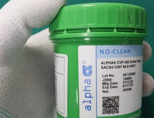
Reflow soldering is the standard industrial process for SMT assembly. Solder paste — a mixture of tiny solder particles and flux — is applied to the PCB pads using a stencil. Components are then placed by pick-and-place machines. The board passes through a reflow oven programmed with a specific temperature profile (typically peaking around 250°C for lead-free solder), which melts the paste and forms reliable solder joints.
2) Hand Soldering
Hand soldering SMT components is practical for prototyping and repair. Key tips include:
- Use a fine-tip soldering iron (0.5–1mm tip) at around 300–320°C.
- Apply a small amount of flux to improve solder flow and prevent cold joints.
- Use fine-gauge solder (0.3–0.5mm diameter) for better control.
- Use tweezers to hold components in place while soldering the first pad.
- Start with 0805 or 1206 components before attempting smaller sizes.
3) Handling Precautions
- ESD Protection: Many SMT components, especially ICs and MOSFETs, are sensitive to electrostatic discharge (ESD). Always use an ESD wrist strap and anti-static mat when handling these parts.
- Storage: Keep moisture-sensitive components (particularly ICs and tantalum capacitors) in sealed, dry packaging with desiccant until ready to use.
- Polarity: Always verify the orientation of polarized components (electrolytic capacitors, diodes, LEDs) before soldering. Incorrect placement can cause circuit failure or component damage.
6. Applications of SMT Components
SMT components are found in virtually every category of modern electronics. Their compact size, reliability, and compatibility with automated manufacturing make them the default choice across industries:
- Consumer Electronics: Smartphones, tablets, laptops, and wearables rely on dense SMT assemblies to deliver high performance in compact form factors. A typical smartphone PCB may contain thousands of SMT components.
- Automotive Systems: Engine control units (ECUs), ADAS sensors, and infotainment systems use SMT components selected for their reliability under vibration, temperature extremes, and humidity.
- Medical Devices: Wearable health monitors, hearing aids, and implantable devices depend on miniaturized SMT components to minimize size and power consumption.
- Industrial Equipment: PLCs, motor drivers, and industrial sensors use SMT components for their robustness and ease of integration into automated production lines.
- IoT and Wireless Devices: The demand for small, low-power connected devices has made SMT components central to the design of modules for Wi-Fi, Bluetooth, Zigbee, and other protocols.
7. Frequently Asked Questions (FAQ)
What is the difference between SMT and SMD?
SMT (Surface Mount Technology) refers to the assembly process of mounting components onto a PCB surface. SMD (Surface Mount Device) refers to the individual components used in that process. The two terms are closely related and often used interchangeably, but strictly speaking, SMT is the method and SMD is the component.
What are the most common SMT component package sizes?
The most widely used sizes for passive components are 0402 and 0603 in professional designs, and 0805 or 1206 for prototyping and hand assembly. For ICs, packages such as SOT-23, SOIC, QFP, and BGA are common depending on pin count and application requirements.
Can SMT components be soldered by hand?
Yes. While industrial SMT assembly uses automated reflow soldering, most SMT components can be hand-soldered with the right tools. Sizes 0805 and larger are practical for beginners. 0603 and 0402 require a steadier hand and finer tools, but are achievable with practice. Very small sizes such as 0201 and 01005 are generally not recommended for hand soldering.
What is the difference between passive and active SMT components?
Passive SMT components — such as resistors, capacitors, and inductors — do not require an external power source to function and cannot amplify signals. Active SMT components — such as transistors, diodes, and ICs — can control or amplify electrical signals and typically require a power supply to operate.
What pick-and-place machine capability is needed for different SMT package sizes?
Standard pick-and-place machines handle components down to 0402 or 0603 reliably. Assembling 0201 and 01005 components requires machines with higher precision vision systems and finer nozzles. For large packages such as BGAs and QFPs, machines need appropriate nozzle sizes and placement force control to avoid damage. It is important to confirm your contract manufacturer’s equipment capabilities before finalizing a component selection.
How do I identify an SMT component without markings?
Many small SMT passives (0402, 0201) have no visible markings due to their size. The best approach is to refer to the PCB schematic or bill of materials (BOM). If those are unavailable, a multimeter can measure resistance and capacitance values. For ICs, a partial code visible under magnification can usually be cross-referenced in an online component database.
8. Summary
Billions of SMT components are used across the industry. However, before a package can be used on a circuit board, the OEM must ensure that its contract manufacturer has the right pick and place machine to handle it. Pcbandassembly has the latest and most advanced machines for all types of PCB assembly. For any type of PCB manufacturing and assembly using SMT components, contact Pcbandassembly today.

Get Quote Free