
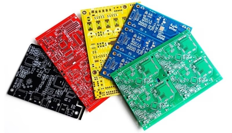
Two years ago, a high-reliability industrial control board assembly line underwent a rigorous audit.Two years ago, a high-reliability industrial control board assembly line underwent a rigorous audit. AOI showed perfect solder fillets, and ICT reported 100% compliance across every resistor, capacitor, and diode — yet during final system-level validation, 4.2% of units failed to boot, with failures spanning microcontroller latch-up, CAN bus communication timeouts, and voltage rail sag under load.
The root cause exposed a fundamental gap: structural tests such as AOI, AXI, and ICT can only confirm that a board is built correctly to the schematic — they cannot verify that the circuit actually operates as intended under real-world conditions. That is precisely the role of Functional Circuit Test (FCT). To meaningfully reduce field failures, rework costs, and production bottlenecks, design and manufacturing engineers must understand how FCT works, how to design for testability, and how to identify and resolve common failure modes within the test fixture itself.
What Functional Circuit Testing (FCT) Actually Is
Functional Circuit Testing (FCT) is the final quality control gate in the electronics manufacturing process. Per IPC-9252A guidelines for electrical testing of PCBs, FCT emulates the operating environment in which the printed circuit board assembly (PCBA) is expected to function — as opposed to structural testing, which only checks the physical assembly.
During an FCT, the Device Under Test (DUT) — sometimes referred to as the Unit Under Test (UUT) — is placed in a dedicated fixture, powered up, loaded with its operational firmware (or test-specific firmware), and subjected to simulated electrical inputs. The test system then monitors the resulting outputs, evaluating the board’s responses against strict design tolerances.
To achieve this, the FCT system must recreate the operational ecosystem of the target application. This ecosystem consists of three core elements:
- Power Supplies: Providing the exact voltage and current profiles the DUT will experience in the field, including power-on inrush currents.
- Stimulus Generators: Generating analog signals, digital logic, and communication protocols (such as UART, I2C, SPI, CAN, or Ethernet) to interact with the DUT’s interfaces.
- Loads: Applying realistic resistive, capacitive, or inductive loads to the DUT’s outputs (such as motor drivers, power rails, or LED indicators) to verify performance under stress.
Ultimately, FCT answers the most important question in manufacturing: Does the board perform its intended system-level functions safely and reliably?
Need PCB Manufacturing or Assembly?
Get a free quote within 24 hours. We specialize in prototype-to-production PCB/PCBA for hardware teams worldwide.
FCT vs. ICT vs. AOI: The Defect Detection Gap
Many procurement managers and hardware designers confuse the coverage of AOI, ICT, and FCT, leading to redundant test setups or catastrophic gaps in quality control. Each methodology operates at a different layer of the assembly process.
Automated Optical Inspection (AOI) is a visual-level test. It uses high-speed cameras and algorithms to check component presence, polarity, alignment, and solder joint quality (governed by IPC-A-600 acceptance criteria). It cannot tell you if a component is electrically dead, if a silicon die is damaged internally, or if a trace has a high-resistance micro-crack.
In-Circuit Testing (ICT) and flying probe testing are component-level electrical tests. By contacting test points across the board, ICT measures the individual values of resistors, capacitors, and inductors, and checks diode orientations and transistor junctions. It also checks for short and open circuits across nets. However, ICT does this under unpowered or statically biased conditions. It does not run the system clock, it does not execute firmware, and it cannot detect signal integrity issues or timing-related anomalies.
Functional Circuit Testing (FCT) bridges this gap. For example: if a 0.1 µF decoupling capacitor was incorrectly populated with a 10 µF capacitor, ICT will flag it immediately. If a microcontroller has a timing-skew defect in its internal PLL that prevents it from locking onto an external 16 MHz crystal, ICT will pass the board as long as the crystal and MCU are physically present and soldered correctly. Only FCT will catch the boot failure.
Defect Detection Coverage by Test Method
| Defect Type | AOI (Optical) | ICT / Flying Probe (Static) | FCT (Dynamic Functional) |
| Solder Bridging / Shorts | High (Visual) | Excellent (Electrical) | Low — can cause damage at power-up |
| Wrong Component Value | Low (markings only) | Excellent (Direct Measurement) | Moderate (only if it alters functional limits) |
| Cold Solder Joints | Excellent (Fillet Profile) | Poor (may conduct at low bias) | High (fails under thermal/load stress) |
| Firmware Integrity | No Coverage | No Coverage | Excellent (Direct execution) |
| High-Speed Bus Communication | No Coverage | No Coverage | Excellent (Real-time protocol verification) |
| Power Rail Voltage Sag Under Load | No Coverage | No Coverage | Excellent (Dynamic electronic loading) |
| Internal IC Die Damage | No Coverage | Poor (unless shorts a rail) | Excellent (Validates true logic state transitions) |
Anatomy of an FCT Station
A reliable FCT station is a complex integration of mechanical, electrical, and software engineering. If any of these systems are poorly designed, the tester will introduce noise, damage the DUT, or generate high false-failure rates.
The Mechanical Bed-of-Nails Fixture
The mechanical fixture provides the physical interface between the DUT and the test instrumentation. It is commonly constructed using G10 (garolite) or acrylic plates and utilizes spring-loaded pogo pins to make contact with test points on the PCB. Precision-ground guide pins must engage with dedicated tooling holes on the DUT. Physical actuation can be manual (toggle clamp), pneumatic (compressed air cylinders), or vacuum-driven.
The Probe and Target Interface
The interface between the pogo pin tip and the PCB pad determines long-term repeatability. Standard pogo pins come in several tip styles optimized for different PCB surface finishes:
- Spear/Point (90°): Best for penetrating flux residues on OSP or HASL finishes.
- Chisel/Blade: Ideal for component leads, connector pins, or lands.
- Serrated: Excellent for clean, flat pads like gold-plated ENIG finishes — distributes pressure across multiple micro-points.
- Cup: Used specifically for contacting male connector pins.
The Instrumentation Stack
Behind the fixture sits the instrumentation rack, typically consisting of programmable test instruments integrated via PXI, LXI, or USB. A standard stack includes:
- Programmable DC Power Supplies: With remote sensing to compensate for voltage drops across long fixture wires and pogo pins.
- Digital Multimeters (DMMs): For precision voltage, current, and low-frequency resistance measurements.
- Digital I/O Cards: To simulate switch presses, read digital indicators, and control relay matrices.
- Oscilloscopes / Digitizers: For measuring rise times, clock frequencies, and power supply ripple.
- Communication Interfaces: Dedicated transceiver modules (CAN, LIN, Ethernet, USB, UART, SPI, I2C) to talk to the DUT’s firmware.
- Electronic Loads: Programmable loads that pull exact dynamic currents from output rails to test buck/boost converters and power stages.
The Test Software Framework
The test software coordinates instrument actions, evaluates measurements against pass/fail limits, and logs data. Common platforms:
| Architecture | Initial HW Cost | Dev Complexity | Measurement Precision | Reconfigurability |
| MCU-Based Controllers | Very Low (<$100) | High (C/C++ required) | Low (on-chip ADCs) | Very Hard |
| PLC-Based Systems | Medium ($500–$2,000) | Medium (Ladder/ST) | Moderate (industrial modules) | Hard |
| PC-Based (LabVIEW / Python) | High ($3,000–$10,000+) | Low to Medium | Extreme (calibrated instruments) | Excellent |
For most small to medium operations, Python-based solutions (PyVISA) offer the best balance of flexibility and cost. LabVIEW remains the industry standard for complex systems but carries significant licensing costs.
Designing PCBs for FCT: Critical DFT Rules
A major bottleneck in manufacturing scale-up is a PCB design that does not consider the physical limitations of automated test equipment. Design for Testability (DFT) is not an afterthought; it is a primary constraint that directly affects test cycle times and fixture longevity.
Test Point Diameter and Pitch Guidelines
Pogo pins are mechanical spring structures subject to alignment tolerances. If test targets are too small or tightly packed, probes will miss their marks, causing false failures and damaging adjacent traces.
- Target Size: Minimum test pad diameter should be 0.8 mm (32 mils). We recommend 1.0 mm (40 mils) for high-reliability production lines.
- Target Pitch: Standard center-to-center spacing for reliable pogo pins is 2.54 mm (100 mils) or 1.91 mm (75 mils). While 1.27 mm (50 mils) pitch probes exist, they are significantly more fragile, have higher contact resistance, and wear out four to five times faster.
- Keep-out Zones: Keep all component bodies at least 1.0 mm (40 mils) from the edge of a test pad to prevent pogo pin heads from striking and cracking SMD packages.
Preventing Mechanical Flexing and Board Damage
When a fixture closes, the combined spring force of dozens of pogo pins can exert significant mechanical pressure on the PCB. Consider this calculation for a typical 80-probe fixture:
Total Force = 80 pins × 2.0 N/pin = 160 Newtons (≈36 lbs of force)
If these probes are concentrated on one side of a 1.6 mm FR-4 board without adequate structural support, the board will bow. This physical flexing causes micro-cracking in multilayer ceramic capacitors (MLCCs) near high-stress zones, breaks BGA solder balls, and tears copper pads from thin signal traces. To prevent this:
- Incorporate mechanical support pinsin the lower fixture plate, positioned directly opposite high-density probing zones.
- Distribute test points evenlyacross the board surface rather than clustering them in one area.
- Keep test points on a single sideof the PCB (preferably the bottom). A double-sided “clamshell” fixture increases cost by 200–300% and drastically increases maintenance complexity.
Signal Integrity on High-Speed Buses and RF Traces
A common error is placing standard test points directly onto high-speed digital buses (USB 2.0/3.0, PCIe, Gigabit Ethernet) or RF lines. A pogo pin and its fixture wiring act as a stub antenna, adding 5–15 pF of parasitic capacitance. For a 480 Mbps USB 2.0 line, this will distort the eye diagram and cause false communication failures.
Recommended techniques:
- AC Coupling Intercept: Place test points on the transmitter side of AC-coupling capacitors, or route through a low-capacitance RF switch IC.
- Connector Loopback: Route high-speed signals directly to their IO connectors (USB-C, RJ45). The test fixture interfaces via a ruggedized mating connector rather than pogo pins.
- Coaxial Probes: If RF lines must be probed directly, design co-planar launches on the PCB and use high-frequency coaxial probes with integrated ground shields.
The Step-by-Step FCT Process on the Production Line
An FCT sequence must be structured with fail-safe steps. Powering up a board that has an undetected short circuit on a low-voltage digital rail will immediately destroy expensive components. The standard FCT workflow follows a gated sequence:
Phase 1: Safe Power-Up and Inrush Analysis
Before full operating voltage is applied, the tester performs a low-voltage resistance check across the primary power rails (e.g., VCC and GND) to confirm there are no hard shorts. Once cleared, the main supply turns on with a programmable current limit activated.
The tester monitors the inrush current waveform. An abnormally high peak current indicates a failing decoupling capacitor or solder bridge on a BGA pin. An abnormally low current indicates a missing power regulator or dead oscillator.
Phase 2: Firmware Flashing & In-System Programming (ISP)
For boards containing microcontrollers, DSPs, or FPGAs, the FCT stage is often where operational firmware is first programmed. The fixture contacts the chip’s programming interface — typically JTAG (IEEE 1149.1), SWD, or a bootloader UART interface. The tester uploads the hex file, verifies the checksum to guarantee data integrity, and resets the target MCU to execute the newly loaded code.
Phase 3: Protocol and Input Verification
With firmware running, the tester establishes a communication link with the DUT. A handshake command is sent (e.g., via CAN or UART) to verify the board’s transceiver, oscillator, and internal memory interfaces are operating. The tester then injects simulated inputs — pulling a digital input low to simulate a button press, or sending an analog voltage to an ADC channel to simulate a temperature sensor — and reads internal register values to confirm the MCU correctly registers these changes.
Phase 4: Dynamic Load Testing
To test power delivery networks and driving stages, the FCT simulates high-stress conditions. The tester activates the DUT’s output circuits (such as a MOSFET switch or motor driver channel) and connects programmable electronic loads to draw the maximum rated current. During this load phase, the tester monitors:
- Voltage stability: Ensuring power rails do not sag beyond ±5% of nominal.
- Thermal buildup: Measured via embedded thermal sensors or IR cameras, verifying power components are dissipating heat correctly.
- Switching noise: Ensuring power supply switching ripple does not couple into sensitive analog measurement traces.
Phase 5: Traceability, Serialization, and Logging
Once all functional parameters have passed, the tester writes unique serialization data directly into the DUT’s non-volatile memory (EEPROM or flash): unique MAC addresses, security keys, or production serial numbers. The complete test log — including precise parametric measurements — is uploaded to the factory’s Manufacturing Execution System (MES). The board is then marked with a pass barcode or laser-etched serial code.
Known Failure Modes of FCT Systems
Every test engineer will eventually face the frustration of a tester that begins failing boards that are actually perfectly good. False failures disrupt production flow, inflate rework costs, and erode trust in the testing process. Most FCT system failures stem from three specific physical root causes.
Contact Resistance Spikes and Probe Contamination
In high-volume lines, pogo pins make thousands of mechanical contacts per day. Over time, flux residues, dust, and microscopic oxidation layers accumulate, dramatically increasing contact resistance.
A brand-new pogo pin typically has a contact resistance below 30 mΩ. In high-volume settings, we have observed contaminated pins spike to over 2.5 Ω. With 1 A of current flowing through such a pin, the voltage drop becomes:
ΔV = I × R = 1 A × 2.5 Ω = 2.5 V
The tester will measure 2.5 V on a 5 V rail and reject the board, despite the board itself being flawless.
The Solution: Implement a strict preventive maintenance cycle. Clean pogo pins every 1,000–5,000 cycles using isopropyl alcohol (IPA) and a stiff-bristle ESD brush. Log probe cycles to replace pins before they reach their rated mechanical life (typically 100,000–500,000 cycles per manufacturer specification).
Per IPC-9252A guidance on test equipment maintenance: any probe reading above 200 mΩ should be flagged for cleaning; any probe exceeding 1 Ω must be replaced immediately.
Mechanical Stress and MLCC Cracking
When the bed of nails exerts uneven pressure on a PCB, the board undergoes mechanical stress. Multilayer Ceramic Capacitors (MLCCs) are highly brittle structures. Under flexing stress, these capacitors develop internal micro-cracks — often too small to be caught by post-stress optical checks, and they do not immediately cause a hard short. When the board undergoes thermal cycling or operational vibration in the field, the micro-crack expands and eventually shorts out the power rail.
The Solution: Perform a strain gauge test on the fixture during its validation phase. Mount strain gauges to a sample PCB near critical components (BGAs and MLCCs larger than 0805) and measure mechanical strain during fixture closure. Per industry best practice, keep the maximum strain below 500 microstrain to guarantee board safety.
Ground Loops and Noise in Measurement Paths
When multiple instruments are integrated into an FCT station, they often share a common ground reference. If the grounds are wired incorrectly, small potential differences between instrument ground terminals cause currents to flow through the ground shields of measurement cables.
Case study: We spent three days tracking down an ADC reading error that only occurred in the tester, never on the bench. The culprit was a ground loop caused by connecting the analog ground reference of our fixture’s measurement card to the main power supply ground at two different physical terminals on the chassis. This created a 120 mV offset that distorted ADC inputs.
The Solution: Star-ground all test instruments to a single, high-conductivity copper bus bar inside the tester cabinet. Keep analog measurement grounds completely isolated from noisy digital grounds and high-current power return lines, joining them only at a single, well-defined common ground point.
Choosing the Right Automation Level for Your Volume
FCT stations range from low-cost manual jigs to million-dollar fully automated inline systems. Over-investing in automation for a low-volume product kills margins; under-investing for high-volume goods creates a massive line bottleneck.
| Parameter | Manual FCT Fixture | Semi-Automatic FCT | Fully Automatic Inline FCT |
| Volume Suitability | Low (<5,000 units/yr) | Medium (5K–100K units/yr) | High (100,000+ units/yr) |
| Operator Interaction | High (manual insert, clamp, remove) | Medium (manual load, pneumatic clamp) | Zero (robotic arms / conveyors) |
| Cycle Time (TACT) | Slow (60–180+ seconds) | Moderate (20–60 seconds) | Extremely fast (<10–15 seconds) |
| Fixture Cost | Very Low ($1,000–$3,000) | Medium ($5,000–$15,000) | High ($40,000–$150,000+) |
| Risk of Human Error | High (misalignment, incomplete clamp) | Low (sensors verify clamp status) | Negligible (fully controlled pathways) |
Frequently Asked Questions
Q1: Can FCT replace ICT entirely to save on production costs?
In very low-volume, low-complexity applications, yes. However, for complex boards, removing ICT is a false economy. Because FCT powers up the entire board, a solder bridge on a 1.2 V power rail will destroy the main SoC before the FCT software can even run its first test line. ICT catches these shorts under unpowered conditions, saving expensive components from destruction.
Q2: What is the ideal contact resistance for an FCT pogo pin?
For a clean, new probe, contact resistance should be below 30–50 mΩ. During production, any probe reading above 200 mΩ should be flagged for cleaning, and any probe exceeding 1 Ω must be replaced immediately. These thresholds are consistent with manufacturer specifications and IPC-9252A electrical testing guidance.
Q3: How do we test wireless interfaces (Bluetooth or Wi-Fi) during FCT?
Wireless interfaces are tested using a shielded RF enclosure built into or around the test fixture. An RF pogo pin or near-field antenna couples the wireless signal to an RF power meter or vector signal analyzer, verifying transmit power, frequency accuracy, and receiver sensitivity while isolating ambient wireless noise.
Q4: What is a “Golden Board,” and how is it used in FCT?
A Golden Board is a master PCB assembly that has been verified to perform perfectly across all design parameters under all environmental extremes. It is used to calibrate and verify the FCT station. If the tester begins failing production boards, testing the Golden Board confirms whether the failure is real or whether the test station itself has drifted out of calibration.
Q5: How do we handle firmware upgrades in the field vs. what was loaded during FCT?
During FCT, we recommend flashing a dedicated “Test Firmware” image containing optimized self-test routines that can toggle I/O, check memory sectors, and verify sensors in seconds. Once the board passes FCT, the final production firmware is flashed over it, or the test code is written to jump directly to the primary bootloader for a final OTA update.
Summary and Practitioner Recommendations
Relying on physical inspection or unpowered testing to guarantee the performance of a complex PCB assembly is a gamble that eventually ends in high field-return rates. Functional Circuit Testing (FCT) is the only methodology that verifies your hardware works under real-world operating conditions, loads, and firmware environments.
When implementing FCT in your next production run, act on these three critical guidelines:
- Enforce DFT early: Never release a PCB design to fabrication without verifying that all test points are at least 1.0 mm in diameter, spaced on a 2.54 mm pitch, and located entirely on the bottom side of the board.
- Protect boards from mechanical strain: Ensure your fixture fabricator performs a strain-gauge analysis. A poorly supported fixture will bend your boards, cracking MLCCs and creating latent field failures that pass test but die in the hands of your end-users.
- Don’t skip ICT on complex designs: Use ICT as your safety filter to catch shorts and assembly errors. This ensures that when boards reach the FCT stage, they can be safely powered up, programmed, and run at full speed without risk of catastrophic damage.
Standards, Tools & Further Reading
Industry Standards
- IPC-9252A — Requirements for Electrical Testing of Unpopulated Printed Boards
- IPC/JEDEC J-STD-001 — Requirements for Soldered Electrical and Electronic Assemblies
- IPC-A-600 — Acceptability of Printed Boards (AOI acceptance criteria)
- IEEE 1149.1 — Standard for Boundary-Scan Architecture (JTAG)
- IPC-7711/7721 — Rework, Modification, and Repair of Electronic Assemblies
Software Platforms
- National Instruments TestStand — com/teststand
- Keysight OpenTAP (open-source) — opentap.io
- PyVISA (Python instrument control) — readthedocs.io
Equipment Vendors
- Keysight Technologies — Test and measurement equipment (keysight.com)
- National Instruments / Emerson — PXI platforms and data acquisition (ni.com)
- Keithley (Tektronix) — Precision measurement instruments (tek.com/keithley)
- Teradyne — Production-scale ICT and functional test systems (teradyne.com)
- Ingun / Yamaichi — Pogo pin and contact probe suppliers
