
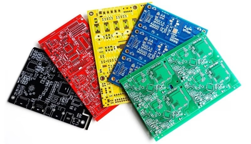
Imagine completing a production run of 400 PCBAs, only to find that a critical IC had been placed with reversed polarity—on every single board. The rework costs, missed deadlines, and damage to your customer relationship can be devastating.
This is precisely the kind of disaster that a well-executed first article inspection (FAI) is built to prevent.
For anyone working in SMT assembly, FAI isn’t just a formality tucked into your quality checklist. It’s a proactive verification step that catches setup errors, component mismatches, and process problems before they propagate across your entire production run. In this guide, we’ll cover everything you need to build or sharpen an effective FAI process—from core principles to modern automated tools.
What Is First Article Inspection in SMT Manufacturing?
First article inspection (FAI) is a structured, documented review of the very first assembled PCB produced in a given production run. Its goal is simple: confirm that the SMT line setup is correct before running the full batch.
Once that first board comes off the line, it’s systematically verified against:
- The bill of materials (BOM)
- Assembly drawings and CAD reference data
- Gerber files and pick-and-place coordinate files
- Customer-defined workmanship specifications
FAI is your production line’s sanity check. It ensures every component is the correct part, positioned accurately, and oriented properly—before you commit to producing hundreds or thousands more.
First Article Inspection vs. Prototype Builds
A widespread misconception is that a successful prototype means FAI can be skipped. These two things serve entirely different purposes.
Prototype builds validate a design. They’re often assembled by hand, in an engineering environment, on equipment that differs from production.
First articles validate your production setup. They’re built on the actual SMT line—using the exact machines, programs, feeders, and processes that will run the full batch.
A prototype that performs flawlessly tells you nothing about whether your pick-and-place program has a rotation error in feeder slot 12, or whether the wrong reel was loaded. That’s FAI’s job.
Why FAI Is Essential for Preventing Batch Defects
The mathematics of SMT defects are unforgiving.
A typical PCB assembly contains anywhere from 200 to 500 surface-mount components, each with multiple solder terminations—meaning a single board can easily present 1,000+ opportunities for error. Scale that across a production run of several hundred units, and a single systematic fault becomes an enormous problem.
If the wrong component has been loaded into a feeder position, every board produced will carry that error. If a reflow profile is inducing tombstoning on 0402 passives, the defect will repeat faithfully across the entire batch.
FAI contains the blast radius of these systematic failures to a single board—not five hundred.
The Real Cost of Skipping FAI
| Scenario | Cost Without FAI | Cost With FAI |
| Incorrect component loaded in feeder (500 boards) | 15,000 in rework | 100 to rebuild one board |
| Reversed IC polarity (200 boards) | 6,000 rework + scrapped parts | Single-board component cost |
| Reflow profile causing solder bridges | Full batch AOI failures + rework | Profile adjustment, minimal waste |
| Wrong stencil used | Entire batch with solder volume issues | One scrapped board + stencil swap |
The takeaway is consistent: FAI converts potential batch disasters into minor, low-cost corrections.
Defects That FAI Catches First
Based on practical SMT production experience, these are the problems FAI surfaces most often:
| Defect Type | Typical Root Cause | How FAI Identifies It |
| Incorrect component value | BOM error or wrong reel loaded | LCR measurement vs. BOM |
| Reversed component polarity | Programming error or feeder mix-up | Visual check against assembly drawing |
| Missing component | Empty feeder or pick failure | BOM cross-check, visual review |
| Tombstoning | Reflow profile issue or pad asymmetry | Visual inspection, process review |
| Placement misalignment | Pick-and-place offset error | CAD comparison, AOI |
| Wrong component package | Incorrect part in feeder | Physical measurement, visual review |
| Solder bridging | Stencil aperture or paste volume issue | Visual and continuity testing |
The Six-Step First Article Inspection Process
Step 1: Documentation Review
Before a single board hits the line, collect and verify all relevant documentation:
- Current BOM revision with approved alternates clearly noted
- Assembly drawings with reference designators
- Gerber files
- Pick-and-place coordinate file
- Any outstanding engineering change notices (ECNs)
- Customer workmanship and specification requirements
Outdated documentation is one of the most common FAI failure triggers. Confirm you’re working from the latest revision every time.
Step 2: Line Setup Verification
Before running the first article board:
- Check solder paste lot number, expiration date, and storage conditions
- Confirm the stencil revision matches the PCB revision
- Audit feeder assignments against the BOM
- Review pick-and-place program for coordinate accuracy and part rotations
- Verify the reflow profile is validated for the assembly
This pre-run check catches obvious problems before any material is committed.
Step 3: First Article Board Production
Run one board through the complete SMT process—solder paste printing, SPI (if available), component placement, reflow soldering, and post-reflow cooling.
Critically, this board must follow the exact same process path as production boards. No hand-placed components, no alternate equipment.
Step 4: Detailed Inspection
Now comes the core of FAI—a systematic physical and functional review of the assembled board:
| Inspection Point | Method | Acceptance Criteria |
| Component presence | Visual, BOM comparison | All BOM items populated |
| Component values | LCR meter | Within specified tolerance |
| Polarity and orientation | Visual vs. assembly drawing | Matches documentation |
| Placement accuracy | Visual, AOI, or CMM | Within IPC-A-610 limits |
| Solder joint quality | Visual, X-ray for hidden joints | Per applicable IPC-A-610 class |
| Labels and markings | Visual | Legible, correctly positioned |
For BGAs, QFNs, and other components with hidden solder joints, X-ray inspection is mandatory—there is no alternative way to verify joint integrity.
Step 5: Documentation and Approval
Every FAI must produce a formal record. Your FAI report should capture:
- Part number and revision
- Serial number or lot identification of the inspected unit
- Inspection date and inspector identity
- Results for each inspection checkpoint
- Any deviations noted, with corrective actions taken
- Approval signatures
This documentation is part of your permanent quality record and is often a contractual requirement in aerospace, medical device, and automotive supply chains.
Step 6: Corrective Action for FAI Failures
When FAI reveals a problem—and it will; that’s the point—a clear corrective action process needs to follow:
| Failure Type | Immediate Action | Root Cause Investigation |
| Wrong component in feeder | Replace feeder, rebuild first article | Review BOM-to-feeder assignment process |
| Orientation error | Correct pick-and-place program | Examine CAD data import workflow |
| Placement offset | Adjust machine, rebuild | Inspect vision system calibration |
| Solder defect | Revise reflow profile or stencil | Verify paste age, aperture design |
| Missing component | Inspect feeder and nozzle condition | Assess pick failure history |
The goal isn’t just to fix the immediate fault—it’s to understand why it occurred and prevent recurrence. Document corrective actions thoroughly; that documentation becomes a knowledge base for future builds.
Manual vs. Automated First Article Inspection
Traditional manual FAI—two inspectors, a microscope, a BOM printout, and a placement diagram—can consume two to three hours on a complex board. That’s valuable line time spent idle.
Manual FAI
How it works: Inspectors visually examine each component under magnification, comparing markings and orientations against the BOM and assembly drawing. LCR measurements verify passive values.
Advantages: Lower equipment cost, flexible across board designs, well-suited to low-volume high-mix environments.
Limitations: Time-intensive, subject to inspector fatigue and inconsistency, documentation is largely manual.
Automated FAI Systems
How they work: Software integrates BOM data, CAD coordinates, and captured board images. The system guides inspectors through each verification step, automatically comparing measurements and flagging anomalies.
| Feature | Benefit |
| BOM-to-CAD integration | Automatic correlation of part numbers to placement positions |
| Automated LCR measurement | Eliminates manual probe repositioning |
| Image comparison | Golden board benchmarking for visual verification |
| Automated report generation | FAI documentation produced in one step |
| Barcode reel scanning | Verifies component reels match BOM before placement |
| Database storage | Searchable historical FAI records for audits |
Advantages: 80%+ reduction in inspection time, higher consistency, automatic documentation, reduced training burden.
Limitations: Significant upfront cost (50,000+), setup time per new product, may require specific CAD data formats.
Choosing the Right Approach
| Production Scenario | Recommended Method |
| Low-volume prototypes (<10 boards) | Manual FAI |
| High-mix with frequent changeovers | Automated FAI |
| High-volume single product | Automated FAI with golden board |
| Aerospace/medical (AS9102 compliance) | Automated FAI for documentation completeness |
| Simple assemblies (<50 components) | Manual FAI may be sufficient |
| Complex assemblies (>200 components) | Automated FAI strongly advisable |
Applicable Industry Standards
IPC-A-610: Acceptability of Electronic Assemblies
The globally recognized standard for visual workmanship criteria, organized into three product classes:
| Class | Application | Quality Level |
| Class 1 | Consumer electronics | Function is the primary requirement |
| Class 2 | Dedicated-service products | Extended life and reliable service expected |
| Class 3 | High-reliability (aerospace, medical, military) | Continuous performance is critical |
Your FAI should assess workmanship against the class your customer has specified.
AS9102: Aerospace First Article Inspection
For aerospace and defense supply chains, AS9102 (latest revision: AS9102C, 2023) is the governing standard. It requires three specific forms:
- Form 1:Part number accountability
- Form 2:Product accountability (materials, processes, special requirements)
- Form 3:Characteristic accountability (dimensions and specifications)
J-STD-001: Requirements for Soldered Electronic Assemblies
While IPC-A-610 defines what acceptable solder looks like, J-STD-001 defines how soldering must be performed. Your FAI should verify process compliance with J-STD-001 requirements.
A Real-World Case Study
A contract manufacturer was setting up production for an industrial motor controller board—roughly 320 components, moderate complexity. The engineering team had approved a substitution for a ceramic capacitor, replacing it with a slightly different footprint from an alternate supplier. The BOM was updated and the change notice closed out.
During first article inspection, the technician noticed that the new capacitor—while electrically identical—had leads spaced 0.4mm closer together than the original. The stencil apertures and pad geometry had been designed for the original footprint. As a result, solder paste was being deposited partially off the pads.
On visual inspection the boards looked acceptable. AOI passed. But under X-ray, the solder joints on those capacitors showed poor wetting and marginal coverage on one termination.
Had this gone to production, the boards would have cleared outgoing inspection—but thermal cycling in the motor controller’s operating environment would have progressively stressed those marginal joints until they failed in the field, likely months after delivery.
FAI caught the mismatch. Engineering adjusted the stencil aperture geometry to match the new footprint, rebuilt the first article, and confirmed clean joints before releasing the run. The customer received 480 boards with no field issues.
That’s the full value of FAI: not just catching obvious errors, but surfacing the marginal conditions that would otherwise escape to the field.
Advanced Techniques
Golden Board Comparison
Automated FAI systems can be configured for golden board methodology:
- Build and exhaustively validate a reference board (the “golden board”)
- Use automated optical comparison to verify that subsequent first articles match the reference
- Any visual discrepancy is flagged for human review
This approach is particularly effective for catching subtle placement drift and cosmetic issues.
Multi-Board FAI for Higher Confidence
| Approach | Description | Best Suited For |
| Single-unit FAI | Inspect first board completely | Standard production |
| Three-board FAI | Inspect first three boards from the run | Complex assemblies, elevated risk |
| Statistical sampling | Inspect random sample from first panel | Very high volume, low complexity |
For high-reliability applications, full FAI on at least one board is always recommended regardless of volume.
Lead-Free and Mixed-Technology Considerations
Lead-free assemblies require additional attention during FAI:
- Higher reflow temperatures demand careful profile validation
- Lead-free solder joints have different visual characteristics than leaded—inspectors must be trained accordingly
- Component temperature ratings must be verified for lead-free compatibility
Mixed-technology boards (combining SMT and through-hole) require separate validation of the wave or selective solder process, with distinct inspection criteria for through-hole joints.
Building a Robust FAI Process
Write Clear Procedures
Your FAI procedure should define:
- Trigger conditions (new product, design revision, process change, supplier change, production resumption after extended gap)
- Required documentation and who is responsible for providing it
- Inspection steps and acceptance criteria for each
- Required tools and equipment
- Documentation requirements and retention
- Approval authority and escalation paths
Train Dedicated Inspectors
FAI inspectors need more than basic assembly knowledge. They must be able to:
- Interpret BOMs, assembly drawings, and Gerber files
- Operate inspection equipment (microscopes, LCR meters, X-ray)
- Apply the relevant workmanship standards (IPC-A-610, J-STD-001, customer specs)
- Produce accurate, complete written records
IPC-A-610 Certified Interconnect Designer (CID) or CIS certification is worth pursuing for inspection staff.
Equip Your Station Properly
A manual FAI station should include at minimum:
- Stereo microscope (10–45× magnification range)
- Consistent, adjustable lighting
- LCR meter for passive verification
- Calipers and dimensional gauges
- X-ray access for assemblies with hidden solder joints
Integrate FAI into Scheduling
FAI must not be an afterthought. Build it into production planning:
- Allocate time between first article completion and production release
- Establish a hard rule: production does not start until FAI is approved
- Define who has authority to accept a conditional FAI result and under what circumstances
- Track FAI metrics over time—pass rates, common failure modes, average inspection duration
Common FAI Mistakes to Avoid
Rushing the process. When a pick-and-place machine sits idle during FAI, pressure to approve quickly is intense. A 90-minute inspection is infinitely cheaper than reworking 500 defective boards.
Using outdated documentation. Always verify the BOM revision before starting. An FAI run against a superseded BOM is worse than useless—it provides false confidence.
Treating “minor” changes as exempt. A changed resistor value can mean a different physical package that requires pick-and-place program adjustment. Changed alternate part approvals can introduce footprint mismatches. There are no truly minor changes in SMT.
Inadequate documentation. “Looked good” is not a quality record. Proper documentation is your protection when a customer raises a concern six months later.
Overlooking process indicators. FAI should identify not just existing defects but emerging process risks. A component that’s slightly skewed but within tolerance today may shift out of tolerance under production conditions or thermal stress.
Frequently Asked Questions
When is FAI required?
- New products being assembled for the first time
- After engineering change notices affecting components, placement, or process
- After process changes (new equipment, new solder paste formulation, revised reflow profile)
- After supplier changes or alternate part approvals
- After production resumptions following an extended gap (commonly 6+ months)
- Whenever specified by contract or purchase order
How long does FAI take?
Manual FAI for a 300-component board typically takes 1.5–3 hours. Automated systems can reduce this to 15–30 minutes. Simple boards with under 50 components may only require 30–45 minutes manually.
Can the same person who set up the line perform the FAI?
Best practice says no. Independence is a fundamental principle—the inspector should not be the person who created the setup being verified. Many standards explicitly require independent review.
What’s the difference between FAI and in-process inspection?
FAI occurs before production and validates the complete setup against documentation. In-process inspection (such as AOI) occurs during production and screens individual boards for manufacturing defects. FAI catches systematic errors; in-process inspection catches random defects. Both are necessary, but they address different failure modes.
Is X-ray inspection required for FAI?
If the assembly includes BGAs, QFNs, or any component with hidden solder joints, yes. There is no way to verify joint integrity under these packages without X-ray.
Conclusion
First article inspection doesn’t generate flashy metrics or make for compelling trade show presentations. But in practical terms, it is one of the most cost-effective quality interventions available to SMT manufacturers.
Done properly, FAI is the mechanism that prevents a single setup error from becoming a warehouse full of defective assemblies.
The core principles are straightforward:
- FAI validates your production setup, not your design
- Systematic errors replicateacross every unit in a run
- Documentationis non-negotiable—for your records and your customers
- Train and equip your inspectors appropriately for your production volume
- Never waive FAIfor changes that seem minor
Whether you run a small prototype shop or a high-volume contract manufacturing operation, the return on a thorough first article inspection is the same: defects caught at one board, not discovered at five hundred.
Start by honestly assessing your current FAI process. Are you consistently catching setup errors before production starts? Is your documentation complete enough to withstand a customer audit? Are your inspectors qualified and properly equipped?
The answers will tell you where to focus next.
