Aerospace PCB Manufacturing
and Assembly Solutions for High-Reliability Electronics
Aerospace PCB manufacturing demands exceptional reliability, precision, and material performance. At PCBAndAssembly, we specialize in producing aerospace-grade circuit boards designed for mission-critical applications. From aerospace PCB assembly to custom design support, our solutions meet the rigorous standards of aviation, satellite, and defense electronics.
What Is an Aerospace PCB?
An aerospace PCB is a printed circuit board specifically engineered for aircraft, spacecraft, satellites, and defense systems. These boards represent the nervous system of modern aerospace technology — connecting and controlling everything from navigation systems to engine monitoring units.
Why Aerospace PCBs Are Different
- Extreme Temperature Range — −55°C to +200°C for space applications
- Up to 2,000 Thermal Cycles — vs. 300 for standard boards
- 20G Vibration Resistance — launch and flight loads
- Radiation Hardening — SEU protection at altitude
- 10–15+ Year Lifespan — often non-maintainable once deployed
- Zero-Defect Tolerance — 100% test coverage mandatory

Aerospace PCB Design Guidelines
Stack-up & Layer Configuration
Most avionics applications fall in the 8–16 layer range. Use symmetrical stack-ups with uniform copper distribution to prevent warping. Specify thickened hole copper at 35μm minimum using pulse plating for resistance to micro-cracking through thermal cycling.
Thermal Management
Use thermal vias (0.3mm drill, 1.0mm pitch) in arrays under high-power components. Consider heavy copper up to 20 oz for power electronics. Metal-core PCBs provide superior heat dissipation and large ground planes for EMI improvement in high-speed designs.
Signal Integrity at High Speed
Aerospace systems increasingly handle 10 Gbps and beyond for satellite links. Use controlled impedance traces with tight tolerances, minimize via stubs, and match differential pair lengths within 5 mils. Maintain ground plane clearance of at least 0.25mm from signal traces.
Redundancy & Fail-Safe Design
Single points of failure are unacceptable. Duplicate key components and circuits for flight-critical systems. Redundant vias on every layer guarantee electrical connection even if individual vias fail. Keep critical components away from board edges where mechanical stress concentrates.
High-Voltage Clearances
For power distribution boards, set clearance distances based on peak operating voltage and altitude. Insufficient clearance can cause arcing at high altitude where air pressure is lower. Reference IPC-2221 for high-voltage clearance calculations at all relevant operating altitudes.
EMI / EMC Design
A solid ground plane is the first line of defense. Add filtering on power inputs and signals crossing functional blocks. Use metal shields or shielding cans for sensitive RF sections. Keep clock traces short and use series termination resistors to minimize radiation from clock harmonics.
Component Placement Strategy
Prioritize high-reliability components away from board edges. Group by function — RF isolated from digital, analog separated from power. Consider thermal distribution to avoid hotspot concentration in compact enclosures.
Design for Testability
Include 100% accessible test points for ICT coverage. Plan test fixture access during layout. Document all test points in the assembly drawing. Testability is a mandatory design requirement in aerospace — not an afterthought.
Aerospace PCB Standards & Certifications
Incorporating the appropriate intent requires understanding the standards that apply to the development of your boards.
IPC Standards for Aerospace PCB
| Standard | Application |
| IPC-A-610 Class 3/3A | Acceptability standards for electronic assemblies; Class 3A is the highest reliability tier |
| IPC-6012DS | Space and military avionics addendum for rigid PCB qualification |
| IPC-6012ES | Performance and certification requirements for aerospace rigid PCBs |
| IPC-6013 | Qualification and performance specification for flexible and rigid-flex PCBs |
| IPC-2221 | Generic standard for PCB design covering layout, materials, and electrical properties |
| IPC-J-STD-001 | Requirements for soldered electrical and electronic assemblies (includes Space Addendum) |
Military Specifications (MIL-PRF Standards)
| MIL Standard | Scope |
| MIL-PRF-31032 | Performance specification for multilayer printed wiring boards |
| MIL-PRF-55110 | Qualification requirements for rigid single/double-sided and multilayer PCBs |
| MIL-PRF-50884 | Performance specification for flexible and rigid-flex printed wiring boards |
| MIL-PRF-38535 | Radiation-hardened component standards for space applications |
| MIL-STD-461 | EMI/EMC requirements ensuring no electromagnetic interference |
Aerospace PCB Material Selection Guide
Material selection is where many aerospace PCB projects succeed or fail. Standard FR-4 simply cannot handle the thermal and mechanical demands of aerospace environments.
Moderate Temp Avionics: High-Tg FR-4
Standard FR-4 has a Tg around 130–140°C. High-Tg FR-4 pushes this to 170–180°C, providing better thermal stability for avionics in climate-controlled environments. More cost-effective than polyimide and suitable where extreme temperatures are not a concern. Not recommended for engine-adjacent or space applications.
Space / High-Temperature: Polyimide
The workhorse for aerospace PCBs requiring extreme temperature performance. Tg exceeding 250°C, operational range −200°C to +300°C. DuPont Kapton polyimide films have proven reliable in everything from satellite wiring to high-temperature engine instrumentation. Low CTE (12–14 ppm/°C), excellent dimensional stability and chemical resistance.
RF / Radar / Comms: PTFE / Teflon
Essential for RF and microwave aerospace applications — radar systems, satellite communications, GPS. Excellent high-frequency signal integrity with low dielectric loss and CTE as low as 10–12 ppm/°C. More difficult to process and more expensive than FR-4. Often used in hybrid stackups alongside polyimide or FR-4 for non-RF sections.
High Precision / Low CTE: Ceramic-Filled Laminates
Rogers RO3003, RT/duroid, and similar ceramic-filled materials offer extremely low dielectric loss, excellent thermal conductivity, and CTE values as low as 6–8 ppm/°C — closely matching copper. Industry standard for high-frequency aerospace PCB designs requiring precise impedance control across the full operating temperature range.
Aerospace PCB Material Comparison
| Material | Tg (°C) | CTE (ppm/°C) | Best For | Relative Cost |
| Standard FR-4 | 130–140 | 14–17 | Not Recommended | 1× (baseline) |
| High-Tg FR-4 | 170–180 | 12–14 | Moderate temp avionics | 1.5–2× |
| Polyimide | 250–260 | 12–14 | Space, high-temp | 3–5× |
| Ceramic-filled | 280+ | 6–8 | High-precision, low CTE | 5–8× |
| PTFE / Teflon | 200+ | 10–12 | RF / microwave / radar | 4–7× |
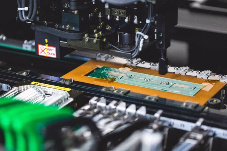
Aerospace PCB Assembly and Testing Processes
Assembly and testing are crucial to ensuring aerospace PCB reliability. At PCBAndAssembly, we perform surface mount technology (SMT) and through-hole assembly using IPC Class 3 standards. Our inspection and testing processes include AOI, X-ray inspection, in-circuit testing (ICT), and functional testing. We also offer flying probe and environmental stress screening (ESS) to simulate real-world operating conditions. These steps ensure each aerospace PCB meets stringent quality and performance benchmarks.
Applications of Aerospace PCBs in Critical Systems
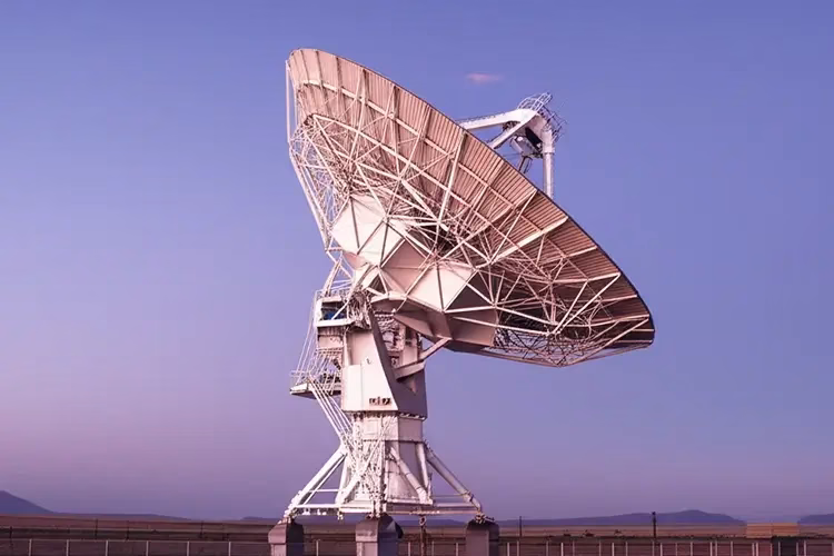
Radio Communication
PCBAndAssembly provides PCBs with precise impedance control and low-loss materials, crucial for maintaining signal integrity and ensuring clear, stable signal transmission in aerospace radio communication systems.

Aerospace Power
Our aerospace power PCBs are manufactured with robust designs and advanced thermal management capabilities (such as thick copper layers) to efficiently handle high voltages and currents, ensuring reliable power distribution even under stress.

LED Lighting System
Our manufacturing supports the precise thermal management and high reliability required for critical LED lighting applications within aircraft cabins and exterior, ensuring consistent performance in challenging environments.

Electronic Flight Instrument
Leveraging our expertise in high density, complexity, and signal integrity, PCBAndAssembly provides the highly reliable PCBs essential for real-time data processing and display in electronic flight instruments, ensuring accurate pilot information.
Aerospace Sensor PCB
Engineered for reliable performance in challenging conditions, our sensor PCBs benefit from our stringent process controls and signal integrity expertise, vital for accurate and reliable readings in applications like altitude and temperature sensing.
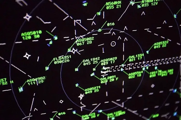
Radar Device
Critical for high-frequency signal processing, our radar PCBs are manufactured with precise impedance control and specialized low-loss materials, supported by our thermal management capabilities, ensuring accurate and reliable target detection.
How to Order Your Industrial Control PCB Assembly
Aerospace PCB Assembly FAQs
What makes aerospace PCB different from commercial PCB?
Aerospace PCBs differ from commercial boards in material selection, design standards, manufacturing processes, and testing requirements. Aerospace boards use high-temperature materials like polyimide (Tg 250°C+) instead of standard FR-4, must meet IPC Class 3/3A acceptance criteria with zero-defect tolerance, undergo environmental stress screening including thermal shock and vibration testing, and require full traceability of all materials and processes. Commercial boards might have 3–5% acceptable defect rates; aerospace boards require 100% reliability.
What certifications should an aerospace PCB manufacturer have?
At minimum, aerospace PCB manufacturers should hold AS9100D certification for quality management. For defense work, ITAR registration is mandatory. Additional valuable certifications include Nadcap accreditation for critical processes, ISO 9001 as a foundation, and specific IPC certifications (IPC-A-610 CIS, IPC-A-620 CIS) for trained inspectors. Always verify current certificates and ask for audit history before engaging any manufacturer.
Which PCB materials are best for space applications?
Space applications require polyimide substrates for their exceptional thermal stability (−200°C to +300°C operational range), low outgassing properties critical in vacuum, and radiation resistance. For RF and microwave space systems, PTFE and ceramic-filled laminates maintain signal integrity. Standard FR-4 is never acceptable for space — it lacks the thermal and radiation resistance required. Material selection should also consider CTE matching with components to prevent solder joint failures through the thousands of thermal cycles a spacecraft experiences over its lifetime.
How long does aerospace PCB manufacturing take?
Aerospace PCB manufacturing takes significantly longer than commercial production due to rigorous quality controls. Standard 4–8 layer aerospace boards typically require 2–4 weeks. Complex multilayer designs (10+ layers) with HDI features may take 4–8 weeks. First Article Inspection adds time for initial production runs. Quick-turn prototypes for design validation are available in 5–10 days, but full aerospace-qualified production always requires extended schedules to complete all required testing and documentation.
What testing is mandatory for aerospace PCB assemblies?
Mandatory testing includes 100% electrical testing (ICT and flying probe), 3D automated optical inspection (AOI), X-ray inspection for hidden joints and BGAs, and functional testing under simulated operating conditions. Environmental testing requirements depend on the application but typically include thermal cycling, thermal shock at 288°C, vibration testing, and burn-in. Space-grade boards require additional radiation testing and outgassing measurements. All test results must be documented for AS9100D compliance and customer traceability requirements.
Do you handle ITAR-controlled programs?
Yes. We are registered with the Directorate of Defense Trade Controls (DDTC) for ITAR compliance. All ITAR-controlled technical data is handled under strict access controls with US Persons only. We can execute program-specific Technology Control Plans (TCP) and Non-Disclosure Agreements as required by your program office. Please indicate ITAR requirements at the time of inquiry so we can set up appropriate handling procedures from the first interaction.
Can you support both prototype and production volumes?
Yes. We support the full product lifecycle from engineering prototype (as few as 5 boards) through low-rate initial production (LRIP) and full-rate production. Prototype builds use the same AS9100D-controlled processes and materials as production — there is no separate “prototype line” that bypasses quality controls. First Article Inspection is completed during the initial prototype phase so production release is straightforward once design is locked.
Need PCB Manufacturing or Assembly?
Get a free quote within 24 hours. We specialize in prototype-to-production PCB/PCBA for hardware teams worldwide.