Military & Defense PCB
Secured solutions for the most demanding Defense & Military PCB applications.
We manufacture MIL-SPEC printed circuit board assemblies for defense electronics, weapons guidance, radar, communications, and UAV systems — where failure rates of 1-in-1,000,000 are not optional.
Fully qualified to MIL-PRF-31032, AS9100D, IPC Class 3/3A, and MIL-STD-810G, with ITAR-registered manufacturing, full material traceability, and Environmental Stress Screening on every program.
What Is an Aerospace PCB?
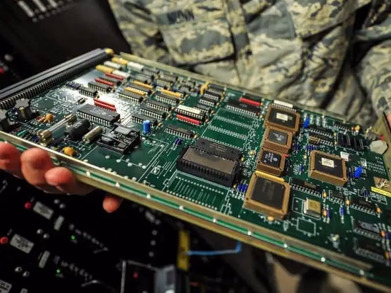
A military PCB is a printed circuit board designed and manufactured to meet MIL-SPEC standards for use in defense electronics, aerospace, and other mission-critical systems. These boards operate in environments that would destroy standard commercial electronics within hours — temperature swings from −55°C to +125°C, constant vibration, exposure to radiation at altitude, salt fog, and the need for decades of reliable operation without maintenance.
The fundamental difference comes down to three factors: reliability requirements, environmental extremes, and regulatory compliance. While a consumer electronics PCB might have an acceptable failure rate of 1 in 1,000 units, military applications often demand failure rates closer to 1 in 1,000,000. Aerospace PCB applications in satellites need to function for 15+ years with absolutely no possibility of repair.
At PCBAndAssembly, we stand as a trusted partner for your military PCB manufacturing needs. We specialize in producing top-quality military printed circuit boards tailored for aviation, defense, space, ground activities, and naval military equipment. Our comprehensive range of composites, materials, and construction options is meticulously designed to uphold the highest standards of quality and adapt to the diverse challenges of military applications.
Commercial vs. Military PCB Comparison
| Characteristic | Commercial PCB | Military / Aerospace PCB |
| Operating Temperature | −10°C to +70°C | −55°C to +125°C |
| IPC Class | Class 1 or 2 | Class 3 or 3A |
| Component Tolerance | 5–10% | 1–2% (MIL-spec) |
| Expected Lifespan | 2–5 years | 15–25+ years |
| Vibration Resistance | Minimal | MIL-STD-810G compliant |
| Documentation | Basic | Full traceability, AS9100D |
| Testing Scope | Functional testing | ESS, burn-in, environmental |
| Acceptable Failure Rate | 1 in 1,000 | 1 in 1,000,000 |
Military PCB Design Best Practices
Stack-up & Aspect Ratio
Maintain maximum aspect ratio of 10:1 for PTH (e.g., 10 mil min hole in 100 mil board). Symmetrical stack-ups with balanced copper distribution on all layers prevent warping under thermal excursions. For 20+ layer designs, use sequential lamination with buried vias to maintain controlled aspect ratios.
Thermal Via Arrays
0.3mm diameter thermal vias on 1.0mm pitch, filled and capped, beneath all high-power components provide direct thermal paths to internal copper planes. Heavy copper up to 20 oz/ft² for power distribution boards. Metal-core substrates where extreme thermal loads require direct conduction to enclosure.
Controlled Impedance
Maintain 50Ω single-ended and 100Ω differential impedance for all high-speed signals with tight manufacturing tolerances. Keep clock traces short with series termination resistors. Minimize via stubs on high-speed nets. Solid ground planes immediately adjacent to every signal layer.
Redundancy & TMR
Single points of failure are unacceptable in mission-critical circuits. Triple Modular Redundancy (TMR) for flight-critical logic. Redundant power paths with automatic failover. Fault containment partitioning between functional blocks — a fault in one section must not propagate.
Conservative Design Rules
Use 4/4 mil trace/space minimum even if your fabricator can achieve 3/3 mil. The margin reduces yield loss and improves long-term reliability. Standard 10 mil finished via holes unless density requires smaller. Larger pads and increased fillet height on SMT joints for vibration fatigue resistance.
EMI Design Discipline
Implement solid ground planes, filtering at all cable interfaces, guard traces around sensitive clocks, and RF shielding cans over high-frequency sections. Keep high-speed traces away from board edges. Respect MIL-STD-461G separation distances between circuit categories — verify in simulation before fabrication.
SEU & Radiation Mitigation
For high-altitude and space applications, implement error-correcting codes for memory, voting circuits for digital logic, and latch-up current limiting. Radiation-hardened components (MIL-PRF-38535) mandatory for space. Document radiation tolerance budget for every component in the design.
100% Testability
Design for 100% ICT net coverage from the start — not as an afterthought. All test points accessible from one side where possible. Document test point list in assembly drawing. Design-for-test is a mandatory requirement on every military program we support, not an optional feature.
MIL-SPEC Standards for Military PCB
The MIL-SPEC framework forms the technical and regulatory backbone of every defense PCB program. Understanding these standards — and ensuring your manufacturer is fully qualified to them — is non-negotiable.
MIL-PRF-31032: The Primary Performance Specification
The MIL-PRF-31032 family includes several slash sheets for specific board types:
| Specification | Board Type |
| MIL-PRF-31032/1 | Rigid multilayer, thermosetting resin |
| MIL-PRF-31032/2 | Rigid single/double layer |
| MIL-PRF-31032/3 | Flexible single/double layer |
| MIL-PRF-31032/4 | Rigid-flex and flexible multilayer |
| MIL-PRF-31032/5 | Rigid multilayer for high-frequency |
| MIL-PRF-31032/6 | Single/double layer for high-frequency |
MIL-PRF-55110: Legacy Standard Still in Use
While no longer used for new qualifications, MIL-PRF-55110 remains active for legacy defense programs designed decades ago. Significant business volume continues to support these legacy requirements and will for years to come. We maintain capability to manufacture to both current and legacy specifications.
MIL-PRF-50884 — Flex PCB
Governs flexible PCBs used in military systems where weight reduction and space constraints are priorities — aircraft wiring harnesses, connections between moving parts in targeting systems, and compact UAV control modules. Flex circuits under this specification require specialized handling and process controls.
Aerospace PCB Design Standards: IPC and AS9100
Beyond military specifications, aerospace PCB design must comply with industry standards that ensure quality and reliability across the global supply chain.
IPC-A-610 Class 3 / 3A
Defines the highest reliability acceptance criteria for electronic assemblies. Class 3A (IPC-6012DS addendum) adds Space and Military Avionics requirements: minimum 50μm external annular ring, 25μm copper plating in PTH, zero tolerance for functional surface defects, and maximum 20% conductor width reduction from artwork.
MIL-STD-810G Testing
Establishes environmental test methods for vibration, thermal shock, humidity, altitude, salt fog, sand and dust exposure, and mechanical shock. Test profiles are tailored to the specific platform — aircraft, ground vehicle, naval, or handheld — each with its characteristic environmental signature.
MIL-STD-461G Compliance
Defines EMI and EMC requirements for defense electronics — ensuring military PCBs do not generate interference that affects other onboard systems and can withstand the electromagnetic environment in which they operate. Compliance verified through controlled chamber testing using military-specified measurement methods.
Military PCB Material Selection
Choosing the right materials can determine whether your military PCB passes qualification testing or fails catastrophically during Environmental Stress Screening. Standard FR-4 is never the answer.
High-Tg FR-4 (170–180°C)
The entry-level material for military PCB applications. Tg 170–180°C provides adequate margin for most avionics in controlled environments. Td around 340°C. More cost-effective than polyimide and suitable for boards not directly exposed to extreme engine or space conditions. Tg must be at least 20°C above maximum operating temperature.
Isola FR408HR
Tg 200°C, Td 360°C. The preferred material for high-speed military digital designs where signal integrity at 10+ Gbps data rates is required. Enhanced CAF resistance prevents conductive anodic filament growth between conductors under high humidity and bias. Widely used in military communication systems and radar signal processors.
Polyimide / Arlon 85N
Tg exceeding 250°C, Td 400°C+. Mandatory for space applications, engine-adjacent avionics, and any board operating beyond 170°C. Excellent dimensional stability through thermal cycling, low moisture absorption, and outstanding chemical resistance. DuPont Kapton and Arlon 85N are proven in decades of space and defense programs.
Rogers 4350B / PTFE
Rogers 4350B (Tg 280°C+) and PTFE/Teflon materials are essential for military RF and microwave applications — phased array radar, electronic warfare, and satellite communication terminals. Extremely low dielectric loss, tight Dk tolerance across temperature, and controlled CTE of 10–12 ppm/°C. Harder to process and higher cost, but irreplaceable for high-frequency performance.
Military PCB Material Thermal Comparison
| Material | Tg (°C) | Td (°C) | Primary Applications |
| High-Tg FR-4 | 170–180 | 340 | General military, controlled-environment avionics |
| Isola FR408HR | 200 | 360 | High-speed digital, aerospace communication boards |
| Polyimide | 250+ | 400+ | Extreme temperature, space, engine instrumentation |
| Rogers 4350B | 280+ | 390 | RF / microwave military, radar |
| Arlon 85N | 250 | 400 | Space, high-reliability defense |
| PTFE / Teflon | 327 | N/A | Extreme RF applications, EW systems |
Surface Finish Options for Military PCB
| Finish | Shelf Life | Wire Bondable | Solder Joints | Best For |
| ENIG | 12+ months | Yes | Good | General military, standard assembly |
| ENEPIG | 12+ months | Yes | Excellent | Mixed assembly, hybrid die attach |
| Hard Gold | 12+ months | Yes | Fair | Edge connectors, high-wear contacts |
| Immersion Silver | 6–12 months | No | Excellent | Cost-sensitive military programs |
| HASL (Lead-Free) | 12+ months | No | Excellent | Legacy compatibility programs |
| OSP | 3–6 months | No | Good | Short shelf life — limited military use |
Military PCB Assembly and Testing Processes
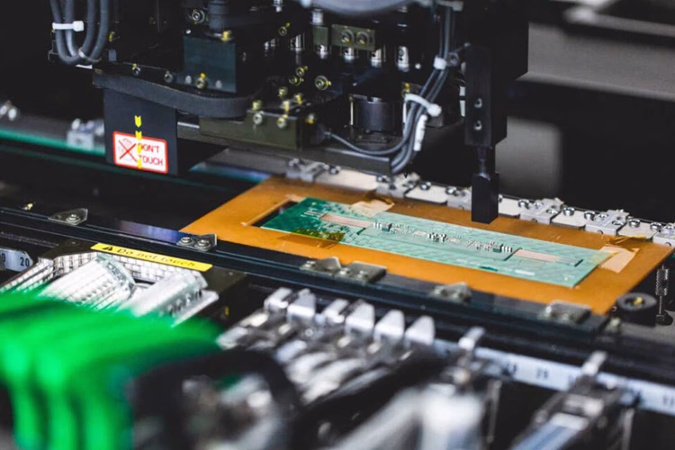
Assembly and testing are crucial to ensuring Military PCB reliability. At PCBAndAssembly, we perform surface mount technology (SMT) and through-hole assembly using IPC Class 3 standards. Our inspection and testing processes include AOI, X-ray inspection, in-circuit testing (ICT), and functional testing. We also offer flying probe and environmental stress screening (ESS) to simulate real-world operating conditions. These steps ensure each Military PCB meets stringent quality and performance benchmarks.
Military PCB Applications

Communication Systems
- Defense navigation and robotic systems
- Radar control and auxiliary power units
- Radio and satellite communication systems
- Underwater navigation systems
- Mobile communication units

Power and Equipment
- LED lighting systems
- Firearm and explosives testing equipment
- Injection and interference systems
- Field computers
- Tactical power units.

Military Vehicles and Armaments
- Unmanned vehicles
- Artillery, motors, and security equipment
- Missile guidance systems
- Tactical vehicles
- Unmanned Aerial Vehicles (Drones)
How to Order Your Industrial Control PCB Assembly
Military PCB Assembly FAQs
What is the difference between IPC Class 3 and MIL-SPEC PCBs?
IPC Class 3 defines acceptance criteria for high-reliability electronic assemblies through the IPC organization’s standards. MIL-SPEC (such as MIL-PRF-31032) adds government-specific requirements including DLA-overseen qualification testing, ongoing compliance verification through monthly sampling, and Technical Review Board governance. A military PCB must meet IPC Class 3 as a baseline, but MIL-SPEC certification adds significant testing, documentation, and process control requirements beyond IPC standards. Many manufacturers can produce IPC Class 3 boards; MIL-PRF-31032 certification requires DLA approval and ongoing compliance — relatively few fabricators hold it.
How long does it take to qualify a manufacturer for MIL-PRF-31032?
The qualification process typically takes 12–18 months from initial application to DLA approval. This includes establishing a Technical Review Board, developing and implementing a quality plan, producing qualification test vehicles, submitting samples for testing at DLA-certified laboratories, and passing an on-site audit. Once qualified, manufacturers maintain certification through monthly sampling, annual audits, and biennial requalification testing. The investment in time and resources is significant — which is why relatively few PCB fabricators hold this certification and why partnering with an already-qualified manufacturer is strongly preferred for most programs.
Can COTS (Commercial Off-The-Shelf) components be used in military PCB assemblies?
Using COTS components in military applications is increasingly common and sometimes encouraged to reduce cost and improve availability. However, components must be evaluated for reliability in the intended operating environment, and upscreening to military temperature ranges is often required. For critical applications, MIL-spec components (MIL-PRF-38535, MIL-PRF-55342, etc.) remain mandatory. When COTS components are used, AS6171 counterfeit avoidance requirements apply and additional qualification testing or documentation is typically needed. Programs using the DESC drawing system can qualify COTS components with appropriate testing and paperwork.
What environmental testing is required for military PCB qualification?
Military PCB qualification typically requires thermal shock, temperature cycling, humidity exposure, random vibration per MIL-STD-810G Method 514, sinusoidal vibration, mechanical shock, altitude simulation, salt fog exposure, and sand and dust exposure. The specific test requirements are defined in the procurement specification and tailored to the platform. For space applications, additional vacuum operation testing and radiation tolerance characterization are required. All tests are performed with boards powered and under functional monitoring where possible, and all results are fully documented for AS9100D compliance.
How do you ensure full traceability for military PCB assemblies?
Full traceability requires documentation at every stage from raw materials through finished product. This includes material certifications for laminates, copper, and surface finishes; component lot codes and date codes linked to manufacturer certificates of conformance; process documentation showing equipment used, operator identification, and process parameters at each step; inspection records with inspector certification; test data for all in-process and final testing; and individual assembly serialization. Our Manufacturing Execution System (MES) automates documentation collection, but paper records and long-term archive (7+ years) are maintained per program requirements. AS9102 FAI reports provide the foundation for the documentation package on every new program.
Need PCB Manufacturing or Assembly?
Get a free quote within 24 hours. We specialize in prototype-to-production PCB/PCBA for hardware teams worldwide.