
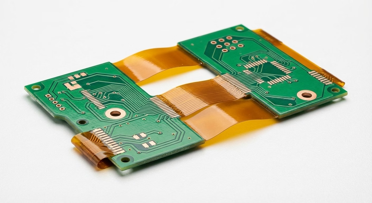
What is Rigid-Flex PCB?
Rigid-flex PCBs are a hybrid circuit board combining components of rigid and flexible PCBs, and are used to connect electronic components in a variety of both consumer and non-consumer devices. This board type can be folded or flexed continuously on the flexible section, which usually joins two rigid parts.
Our Rigid-Flex PCB Manufacturing Capabilities
| feature | ability |
| Number of layers | 2-32 |
| quantity | 1-10000+ |
| quality level | Standard IPC 2 |
| Build time | 2-20 days |
| Request Quote | 1-2 days |
| Material | DuPont, Fr4, polyimide |
| Board size | Minimum 6*6mm
Maximum 457*610mm |
| Plate thickness | 0.6-2mm |
| Copper thickness | 0.5-2 oz |
| Surface treatment | Lead-free HASL – RoHS, immersion gold, electroplating gold, IM-Ag, electroplating silver, HASL |
| Drilling accuracy | +/-0.05mm |
| Other technologies | HDI gold finger reinforcement board (only suitable for PI/FR4 substrate) |
What Types of Rigid-Flex PCB Stack-Ups and
Structures are Available?
Rigid-flex PCB structures are classified by how the flexible layers and rigid sections are combined. Options include single- or double-sided flex, multilayer rigid-flex, and laminated or non-laminated configurations, each designed to meet specific routing, bending, and space requirements.
Single-Sided Rigid-Flex
This configuration features a single copper layer on the flexible circuit portion, bonded to one or more rigid sections.
It’s commonly used for low-complexity interconnects such as sensor modules, camera assemblies, or display connections.
These flex PCBs are easy to manufacture and offer good mechanical bend performance, especially in dynamic applications with limited routing paths.
Double-Sided Rigid-Flex
Two conductive layers are routed on the flexible portion, allowing signal layers or ground planes to run in parallel.
This enhances circuit density while preserving flexibility. Plated through-holes are used to connect both copper layers.
Applications include flex and rigid-flex PCBs in consumer devices, medical diagnostics, and industrial sensors requiring greater layout complexity.
Multilayer Rigid-Flex
The flexible sections contain three or more copper layers laminated together with polyimide dielectrics and adhesive systems.
These rigid-flex printed circuit boards support high-density routing, controlled impedance, and advanced grounding schemes.
Microvia and HDI-compatible structures can be integrated to meet demanding PCB design needs. Used in aerospace, automotive ADAS, and high-end wearables.
Non-Lamination Flex & Rigid Board
In this approach, the flexible PCB and rigid board portions are manufactured as separate subassemblies andconnected using external connectors or mechanical interconnects.
The flex section typically consists of polyimide or polyester, while the rigid section uses FR-4 or CEM-1.
This design allows for simplified rework or replacement but lacks the electrical reliability and mechanical stability of laminated rigid-flex circuit boards.
Laminated Rigid-Flex PCB Structures
This structure fuses rigid and flexible sections into a single unit using heat, pressure, and adhesive systems during lamination. It offers superior reliability and is standard for permanent rigid-flex integration.
Flex Layer in Inner Layer: The flex layer is embedded between rigid layers, protected from external stress.
Flex Layer on Outer Layer: Flex layers are positioned outside the rigid core for applications requiring repeated bending.
Rigid-flex PCBs are made from four core material groups: conductors, adhesives, insulators, and surface finishes.
| Material Type | Example / Subtype | Function |
| Conductors | Rolled Annealed (RA) Copper | Used in flexible circuits requiring repeated bending. It offers superior ductility, a grain structure aligned with the bend axis, and a reduced risk of micro-cracking. |
| Electro-Deposited (ED) Copper | Preferred in rigid sections and some static flex zones. Provides high conductivity and fine trace definition but lower flex fatigue performance than RA copper. | |
| Adhesives | Epoxy | Strong adhesion with low moisture absorption. Tg typically ≥135 °C. Commonly used between copper and dielectric layers in rigid zones. |
| Acrylic | High peel strength, chemical resistance, and thermal stability (Tg ~150 to 200 °C). Often selected for rigid-flex bonding interfaces. | |
| Pressure Sensitive Adhesive (PSA) | Low-temperature bonding layer is used to attach stiffeners or mount flex circuits. Limited to non-electrically active zones. | |
| Polyimide (as adhesive) | Extreme thermal resistance (>250 °C) and chemical durability. Used in aerospace-grade flexible PCB assemblies exposed to harsh environments. | |
| Adhesiveless Base Material | Polyimide is cast directly onto copper foil. Eliminates adhesive interface, improves flexibility, reduces Z-axis expansion, and enhances thermal reliability in dynamic flex circuits. | |
| Pre-preg (Resin-coated Glass) | Dielectric bonding sheet used during multilayer lamination in rigid areas. Properties depend on the resin system (Tg, flow, Dk/Df). | |
| Insulators / Dielectrics | FR-4 | Standard rigid PCB core. Tg typically 135 to 170 °C. It provides mechanical support and a routing platform for rigid flex boards. |
| Polyimide | High-flex, high-temperature material (Tg >250 °C). Used in flexible sections due to superior bend endurance and dimensional stability. | |
| CEM-1 | Cellulose-based composite alternative to FR-4. Used in cost-sensitive rigid sections with low mechanical stress. | |
| Polyester (PET) | Flexible and thermally stable (~120 to 150 °C), lower cost than polyimide. Used in basic flexible PCB assemblies. |
Disadvantages of Rigid-Flex PCB
Despite its advantages, rigid-flex PCB also has some drawbacks:
- High Production Complexity
The process of combining flexible and rigid materials is more complex than manufacturing purely rigid or flexible boards. This complexity can lead to longer production times and increased costs. - High Design Requirements
Designing a rigid-flex PCB requires precise planning, especially when considering flexible section bending radii, stress concentrations, and thermal management. Poor design can lead to reduced board performance or failure.
Design Issues and Considerations for Rigid-Flex PCB
- Design Specifications and Requirements
It is essential to adhere to strict design specifications when creating a rigid-flex PCB. Ensure that the bending radius of the flexible sections meets manufacturing requirements to prevent material damage or board failure. - Stress Concentration and Thermal Management
Special attention should be paid to stress concentration issues in the design. Use appropriate transition areas and reinforcement structures in bending regions to minimize stress concentrations. Additionally, consider thermal management to ensure effective heat dissipation, preventing board failure due to overheating. - Circuit Layout and Routing
When laying out the circuit, carefully plan the routing for both rigid and flexible areas. Avoid high-frequency signals and high-power circuits in flexible sections to minimize electromagnetic interference and signal integrity issues. - Connections and Soldering Techniques
The connection and soldering techniques for rigid-flex PCBs are critical. Use suitable soldering technologies to ensure reliable connections between rigid and flexible parts. Consider potential damage to flexible sections during soldering and choose appropriate materials and processes. - Material Selection
Selecting the right materials is crucial for the performance of rigid-flex PCBs. Typically, rigid sections use traditional FR-4 materials, while flexible sections use high-performance polyimide (PI) materials or other flexible circuit board materials. Ensure material compatibility to guarantee overall board stability and reliability.
Disadvantages of Rigid-Flex PCB
Despite its advantages, rigid-flex PCB also has some drawbacks:
- High Production Complexity
The process of combining flexible and rigid materials is more complex than manufacturing purely rigid or flexible boards. This complexity can lead to longer production times and increased costs. - High Design Requirements
Designing a rigid-flex PCB requires precise planning, especially when considering flexible section bending radii, stress concentrations, and thermal management. Poor design can lead to reduced board performance or failure.
PCBAndAssembly provides high-quality rigid-flex PCB manufacturing and assembly services. Rigid-flex PCBs combine flexible and rigid layers, offering durability and space efficiency for complex electronic designs. We ensure precision engineering, strict quality control, and fast turnaround times to meet your requirements.
Rigid-Flex PCB Manufacturer FAQs
What IPC standards do your rigid-flex boards meet?
All rigid-flex PCBs are manufactured following IPC-6013 Class 3. On request, we also support IPC-A-610 and IPC-1791 requirements for medical and military applications.
What’s the minimum bend radius for flex sections?
Bend radius depends on the number of layers and overall stack-up thickness. For most builds, the minimum is 6 to 10× the board thickness for single- and double-layer flex, and 10 to 15× for multilayer rigid flex PCB stack-ups.
Can I receive custom stack-up diagrams for approval?
Yes. We provide standard reference stack-ups and custom diagrams based on your required impedance control, flexible material thickness, and mechanical layout constraints.
What is the minimum annular ring for vias in flex-rigid technology?
Annular ring requirements vary by Via type and class. Mechanically drilled vias typically require a 3 mil ring, while laser-drilled microvias require 2 mils. All via structures follow the guidelines outlined in IPC-6013.
Do you support Altium/IPC-2581 files?
Yes. We accept Altium, Gerber, and IPC-2581 file formats, including .PcbDoc and Pcb, for all rigid-flex PCB fabrication projects.
