
If you’ve ever watched a batch of fully assembled boards go up in smoke during a final quality check, you know the dread of a failed high- potential test. After 15 years on the factory floor, I’ve learned that a Hipot failure is rarely a fluke; it’s almost always a design or process error that should have been caught much earlier. By exploring the mechanics of dielectric withstand testing, this article provides the specific parameters, standards, and practical adjustments needed to protect both your yields and your customers.
What Is Hipot Testing?
High Potential (Hipot) testing — formally called Dielectric Withstand Voltage (DWV) testing — verifies that current cannot flow where it must not. Standard functional testing confirms performance under normal operating conditions. Hipot testing goes further: it forces the board’s substrate and insulating barriers to withstand transient overvoltage spikes, exposing latent manufacturing flaws before the assembly is sealed and shipped.
How it differs from other electrical tests:
| Test Type | Applied Voltage | Primary Measurement | Core Purpose |
| Continuity Testing | Low (<10V DC) | Resistance (Ω) | Verifies circuit paths and low-resistance connections. |
| Insulation Resistance (IR) | High (500V DC) | MΩ or GΩ | Measures exact resistance of dielectric under stress. |
| Dielectric Withstand (Hipot) | Very High (1–5 kV) | Leakage Current (mA/µA) | Verifies insulation holds without arcing or breakdown. |
| Flying Probe | Low (<250V) | Open/Short detection | Identifies assembly faults and layout errors. |
Why Hipot Testing Matters
Hipot testing catches insulation failures that no other production test will find. There are four practical reasons to include it in every production flow:
- Safety compliance. IEC 60950, UL, CSA, and most international safety standards require Hipot testing for product certification. Without a passing result, the product cannot enter many markets.
- Early defect detection. Insufficient trace clearance, surface contamination, insulation pinholes, and poor dielectric material all surface during Hipot testing — and nowhere else.
- Cost reduction. Finding an insulation defect at the factory costs roughly 1/100th of addressing the same defect after shipment. Field recalls and liability claims dwarf in-factory rework costs.
- Documented quality. In medical, aerospace, and automotive applications, a per-board Hipot record is often a contractual requirement.
The Physics of Dielectric Breakdown
Every dielectric material — from standard FR-4 to high-performance polyimide — has a finite dielectric strength. This is the maximum electric field it can withstand before physical breakdown occurs.
When the applied voltage exceeds that threshold, electrons are stripped from their molecular bonds, triggering an avalanche breakdown. The material instantly transitions from an open circuit to a highly conductive path. On a PCB, the resulting arc carbonizes the surrounding epoxy resin, creating a permanent conductive channel.
Key factors that affect dielectric strength:
- Resin-to-glass ratio in prepreg and core laminates
- Dielectric constant(Dk) and dissipation factor (Df) of the polymer matrix
- Microscopic voids, micro-cracks, or air bubbles within the laminate
- Surface finish and presence of ionic contamination or flux residues
- Moisture absorption — dramatically reduces FR-4 breakdown voltage
Choosing Between AC and DC Hipot Testing
The choice between AC and DC test voltage is one of the most consequential decisions in your test program. It determines the stress profile applied to the board and the likelihood of false-positive failures.
| Feature | AC Hipot | DC Hipot |
| Peak Stress | Alternating (+/−); peak = 1.414× RMS | Constant fixed level |
| Capacitive Leakage | Continuous reactive current flow | Only during initial ramp-up |
| Discharge After Test | Not required | Mandatory — board stays charged |
| Best For | AC-line components, EMI filters | DC designs, multilayer HDI stacks |
| Leakage Measurement | Total current (resistive + capacitive) | True resistive leakage only |
| Regulatory Acceptance | Preferred by most agencies | Acceptable with voltage correction factor |
Practical guidance: For high-capacitance multilayer boards, DC Hipot is generally preferred. AC voltage drives continuous reactive current through parasitic capacitance (I = 2πfCV), which frequently triggers false leakage failures unless a high-current tester is used. DC testing, once the initial charging phase is complete, isolates true resistive leakage — critical for HDI designs where layers are tightly coupled. AC testing remains the better choice for line-powered systems where insulation is subjected to alternating fields during actual operation.
Voltage Calculations and IPC Parameters
Standard Test Voltage Formula
The most widely accepted rule:
Hipot Test Voltage = (2 × Working Voltage) + 1000 V
Example: A board operating at 240 V AC → (2 × 240) + 1000 = 1480 V AC test voltage.
DC equivalent: When substituting DC for AC testing, multiply the AC target by 1.414 to apply equivalent dielectric stress. For 1480 V AC → 1480 × 1.414 = 2093 V DC.
| Nominal Working Voltage | AC Test Voltage (RMS) | Equivalent DC Test Voltage | Regulatory Standard |
| 12V / 24V DC | 500V AC | 707V DC | IPC-TM-650 Condition A |
| 120V AC | 1240V AC | 1753V DC | UL 60950-1 / IEC 60950 |
| 240V AC | 1480V AC | 2093V DC | IEC 62368-1 |
| 480V AC | 1960V AC | 2771V DC | UL 508C |
IPC-TM-650 Test Conditions
| Parameter | Condition A | Condition B |
| Test Voltage | 500V DC | 1000V DC |
| Ramp Rate | 1 s per 100V | 1 s per 100V |
| Dwell Time | 30 s (+3/−0 s) | 30 s (+3/−0 s) |
| Leakage Limit | ≤1 mA (≤10 µA for medical) | Per specification |
Pre-test requirement: Boards must complete all physical stress, humidity exposure, and thermal shock cycles before Hipot testing begins.
Manufacturing Defects That Cause Hipot Failures
Hipot testing is effective precisely because it exposes microscopic defects invisible to optical inspection or low-voltage electrical tests. Each failure mode points to a specific breakdown in the manufacturing process.
Note on surge-suppressive components: Always isolate or desolder MOVs, gas discharge tubes, and similar devices before routing boards to the Hipot station. These components are designed to clamp high voltage to ground — they will trigger a false failure and may be permanently destroyed in the process.
Common physical failures:
- Drill wander / hole-wall breakout. Misaligned drill bits reduce the distance between plated through-holes and adjacent inner-layer copper planes.
- Prepreg voids and delamination. Air pockets or resin starvation inside the laminate have far lower dielectric strength than solid FR-4.
- Solder mask pinholes. Microscopic openings allow moisture and dust to settle between closely spaced traces, bridging the isolation gap.
- Copper slivers / incomplete etching. Residual metal from the etching process creates sharp points that concentrate the electric field.
- Ionic contamination. Unwashed flux residues act as conductive paths under high voltage, promoting dendritic growth and leakage current.
- Insufficient clearance. Trace spacing or plane-to-board-edge distances that meet low-voltage design rules may still fall short at test voltage levels.
Failure Analysis Decision Tree
| Symptom | Likely Cause | Investigation Method |
| Immediate breakdown | Short circuit or insufficient clearance | Cross-section analysis |
| Gradual current increase | Contamination or moisture | Clean, bake, then retest |
| Intermittent failures | Marginal clearance or particle contamination | Microscopy / SEM inspection |
| Surface arcing | Surface contamination or conformal coat issue | Visual inspection, ion chromatography |
| High leakage, no breakdown | Bulk material degradation or moisture | Material testing, TGA |
Step-by-Step Hipot Test Procedure
Pre-Test Preparation
Follow these steps before initiating any high-voltage test:
- Use only fresh specimens. Never Hipot a board that has already been exposed to high voltage or a prior Hipot test.
- Condition the environment. For qualification testing, hold specimens at 23°C ±3°C and 50% ±10% RH for 24 hours.
- Visually inspect. Check for visible contamination, flux residue, or physical damage before any electrical test.
- Set tester parameters. Configure peak voltage, ramp rate (typically 5% of peak per second), hold time, and leakage current trip level.
Production SOP
| Step | Phase | Technical Requirement | Impact |
| 1 | Safety Interlock Check | Verify light curtains, safety mats, and dual-hand control switches. | Prevents operator exposure to live high-voltage elements. |
| 2 | Ground Integrity Check | Confirm tester chassis and fixture are bonded to verified earth ground. | Eliminates floating potentials that skew leakage measurements. |
| 3 | Parameter Verification | Set voltage, ramp time, dwell time, and leakage current trip limits. | Ensures compliance with IPC or UL specifications. |
| 4 | Dummy Load Test | Run a calibration check using a known high-value resistor. | Prevents release of untested boards due to a blind tester. |
| 5 | DUT Isolation | Disconnect MOVs, gas discharge tubes, and small bypass capacitors. | Protects voltage-sensitive devices from dielectric rupture. |
| 6 | Connection Sequence | Attach ground lead first, then the high-voltage probe. | Prevents HV spikes from finding alternative ground paths. |
| 7 | Voltage Ramp | Increase voltage at the rate defined by the standard (100–500 V/s). | Minimizes capacitive inrush currents that cause nuisance trips. |
| 8 | Dwell Phase | Hold peak voltage for the specified duration (typically 60 s). | Gives latent defects time to fail under sustained stress. |
| 9 | Discharge Phase (DC) | Keep ground connected until residual voltage drops below 50V. | Prevents shock from stored capacitive energy. |
| 10 | Data Logging | Record leakage current, peak voltage, and pass/fail to MES. | Provides traceability for safety audits. |
Test Methods by Volume
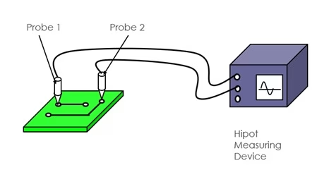
| Method | Equipment | Operator Involvement | Best For |
| Manual Probing | Hipot analyzer + probes | High | Prototypes, low volume |
| Fixture Testing | Analyzer + custom fixture | Medium | Mid-volume production |
| Flying Probe | Automated flying probe machine | Low (fully automated) | High volume, multiple test pairs |
Safety Precautions
High-voltage testing presents real electrical hazards. The following rules are not optional:
- Only qualified personnel may perform Hipot testing — no exceptions.
- Never bypass safety interlocks or guarding systems.
- Discharge the DUT before handling — especially after DC testing.
- Use insulated fixtures rated for the test voltage.
- Keep flammable materials out of the test area.
- Post warning signs and maintain active high-voltage indicator lights.
- Ensure an emergency stop is reachable from the operator position.
- Provide adequate ventilation — AC Hipot testing produces ozone.
- Follow lockout/tagout procedures during fixture maintenance.
- Never work alone when performing high-voltage tests.
Common Setup Mistakes That Cause False Failures
A significant share of Hipot failures on the production floor are caused by the test setup, not the board. The most common culprits:
- Cable capacitance in AC mode. Long, unshielded test leads introduce parasitic capacitance. The resulting reactive current can trip the leakage limit on a perfectly good board. Use shielded coaxial cables and keep leads as short as possible.
- Low-insulation fixture materials. Fixtures made from standard plastics can develop surface tracking at high voltage. Use Delrin or PTFE for all high-voltage contact areas.
- Thermal state of the board. Testing a board immediately after reflow can produce false failures. Allow boards to return to ambient temperature first.
- Repeat testing of failed boards. Each successive Hipot test degrades the insulation of a borderline board further. Investigate the root cause before retesting.
- Inconsistent contact. Manual probing introduces variation in contact pressure and location. Automated relay matrix systems deliver repeatable, consistent connections.
Integrating Hipot Testing into the Production Flow
Recommended Test Stages
- Incoming material. Test laminate samples to verify dielectric properties match specifications before committing to production.
- After lamination. For multilayer boards, test after lamination to catch registration and lamination defects early — before inner layers are inaccessible.
- Final electrical test. Include Hipot in the standard electrical test sequence, after continuity and isolation testing.
- Post-assembly (PCBA). Some applications require a second Hipot test after SMT assembly to confirm that the assembly process has not compromised insulation.
Testing Frequency by Product Type
| Product Type | Recommended Frequency |
| Consumer Electronics | Sample testing (statistical process control) |
| Industrial Equipment | 100% testing recommended |
| Medical Devices | 100% testing required |
| Aerospace / Military | 100% testing with full documentation |
| Automotive Safety | 100% testing per functional safety requirements |
Equipment Selection and Calibration
Tester Specifications
A production-grade Hipot tester should provide:
- Adjustable output: 0–6 kV AC and/or 0–6 kV DC minimum
- Programmable ramp rates
- Adjustable current trip: 0.5 mA to 20 mA
- Automatic discharge function (mandatory for DC testing)
- Data logging and MES integration capability
Calibration Requirements
- Annual calibration to NIST-traceable standards — required for IEC 60950 compliance.
- Daily verification using a certified dummy-load resistor at the start of each shift.
- Documented calibration records with clear out-of-tolerance protocols.
Key Standards Reference
| Standard | Source | Description |
| IPC-TM-650 | IPC | Hipot test methods for bare PCBs |
| IPC-6012 | IPC | Rigid PCB qualification and performance specs |
| IPC-9252A | IPC | Electrical test requirements and guidelines |
| IPC-2221 | IPC | Trace spacing and clearance design rules |
| IEC 60950-1 | IEC | IT equipment safety (3 kV AC input-to-output) |
| IEC 60601-1 | IEC | Medical equipment (4 kV AC requirement) |
| UL 60950-1 | UL | US safety requirements for IT equipment |
Troubleshooting Guide
False Failures (Good Boards Failing)
- Confirm test voltage is not set higher than the specification.
- Check that the leakage current trip threshold is not too low.
- For AC testing, verify Y-capacitors or filter capacitors are not generating excessive charging current.
- Inspect probe contacts for proper seating and consistent pressure.
- Rule out external electromagnetic interference.
Inconsistent Results
- Monitor ambient humidity — it is the single largest environmental variable in Hipot results.
- Inspect fixture contacts for wear and replace on a scheduled cycle.
- Verify board positioning is repeatable — use locating pins in the fixture.
- Confirm tester calibration is current.
Confirmed Failures
- Do not repeat the test. Consecutive tests on a failed board degrade insulation further and compromise failure analysis.
- Investigate the root cause before resuming production.
- Cross-section failed units to identify the physical breakdown location.
- Check other boards from the same production batch and lot.
- Review any recent process changes — lamination cycle, etch chemistry, cleaning process.
FAQ
Q: What is the difference between Hipot and Dielectric Withstand testing?
They are the same test. “Hipot” is industry shorthand for “High Potential.” “Dielectric Withstand” is the formal term used in UL, IEC, and IPC-TM-650 standards.
Q: What is the difference between Hipot and an insulation resistance (IR) test?
The IR test measures the quantitative resistance value of the insulation at a moderate voltage (typically 500 V DC). Hipot is a pass/fail overstress test at a much higher voltage. The two are complementary: a board can pass IR and still fail Hipot if it has a localized weak spot that only breaks down at elevated stress.
Q: Does Hipot testing damage a good PCB?
A correctly configured Hipot test is non-destructive for boards with sound insulation. If insulation defects are present, the test will cause a localized arc that permanently carbonizes the substrate — which is the intended outcome. Never exceed the specified voltage or dwell time, and avoid testing boards multiple times without investigation.
Q: Why must MOVs be removed before a Hipot test?
Metal Oxide Varistors are surge suppressors. They are designed to conduct when voltage exceeds their clamping threshold — which is exactly what Hipot voltage does. An active MOV will clamp the test voltage to ground, triggering a false leakage failure and potentially destroying the component.
Q: How long should a Hipot test last?
IPC-TM-650 specifies 30 seconds for qualification testing. Most safety standards call for 60 seconds as the full dwell time. Production conformance testing allows a minimum of 10 seconds. Some manufacturers use 1–2 seconds with a 20% voltage increase for high-volume lines. Whatever duration is chosen, it must be applied consistently across all units.
Q: Can a standard digital multimeter substitute for a Hipot tester?
No. A multimeter applies at most 9 V DC for resistance measurement. That voltage is too low to stress insulating materials, bridge microscopic voids, or detect any insulation weakness. A dedicated Hipot tester is required.
Q: What does arc detection do in a modern Hipot tester?
Arc detection monitors high-frequency current spikes caused by partial or corona discharges. These spikes indicate early insulation breakdown before a full catastrophic failure occurs, allowing the tester to flag marginal boards that would otherwise pass a simple leakage-current check.
Q: How often must Hipot equipment be calibrated?
Safety standards require annual calibration by an accredited laboratory with NIST-traceable standards. In addition, operators must perform a daily functional verification at the start of each shift using a known dummy-load resistor to confirm that the trip circuit is operational.
Q: Do all PCBs require Hipot testing?
Not all applications require it, but any product where an insulation failure could create a safety hazard should undergo Hipot testing. Power supplies, medical devices, industrial equipment, and products subject to safety certification all require it. Even for consumer electronics, Hipot testing catches defects no other production test will find.
Summary
Hipot testing is the production floor’s last line of defense against insulation failures that reach end users. Its effectiveness depends entirely on three things: correct parameter selection, consistent procedure, and thoughtful design-stage planning.
Key takeaways:
- Use (2 × Working Voltage) + 1000 V as the starting point for test voltage.
- Choose DC for HDI and multilayer boards. Choose AC for line-powered systems and regulatory preference.
- Follow IPC-TM-650 for dwell time, ramp rate, and leakage limits.
- Isolate all surge-suppressive components before testing.
- Never repeat-test a failed board — investigate the root cause first.
- Plan test parameters during the design phase, not after tapeout.
Designing adequate clearances, selecting the right dielectric material, and setting realistic leakage limits up front eliminates the majority of production-floor Hipot failures before a single board is built.