PCB Manufacturing and Assembly: Know the Step-By-Step Process
PCB stands for printed circuit boards, are designed for modern [...]
Get Your PCB Quote!

Table of Contents
PCB stands for printed circuit boards, are designed for modern electronic components such as televisions, smartphones, medical instruments. Both amateur electronics enthusiasts and professional engineers who grasp PCB manufacturing find themselves uncovering fundamental technological insights.
We will guide you through each phase of PCB fabrication and assembly with easy-to-understand explanations suitable for newcomers to electronics.
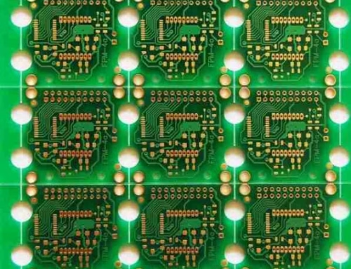
PCB Fabrication: Building the Bare Board
Here’s how it happens:
Step 1: Design and Planning
Everything starts with a vision. Manufacturers of electronics introduces digital footprints, named schematics with the software, including KiCad, Eagle, Altium Designer. The diagram shows both the placement of components and their interconnections through copper traces. The schematic serves as a detailed guide that directs the entire process that follows.
After completing the schematic it transforms into a layout displaying both component locations and trace positions. The layout gets converted into Gerber files which serve as a universal circuit board manufacturing blueprint for building the board.
Step 2: Material Selection
PCB construction generally involves a fiberglass base material known as FR- 4 which receives a bobby coating. The selection of materials for PCB construction varies grounded on operation conditions where flexible PCBs use polyimide for inflexibility and high- frequency bias use accoutrements that reduce signal loss. Multi-layer boards use thin bobby and separating layers piled together to produce a thick circuit design.
Step 3: Printing the Circuit Pattern
Now, the design comes to life. The photolithography process enables printed circuit board manufacturers to imprint circuit patterns on copper-clad boards. The copper receives a photosensitive film (photo-resist) treatment followed by the creation of a PCB design film mask through plotter printing. UV light exposure causes the photo-resist to solidify where copper traces need to stay while leaving other areas soft to be eliminated.
The repeated photolithography process for inner layers of multi-layer PCBs involves marking conductive copper paths with black ink and indicating non-conductive sections using clear ink.
Step 4: Etching
In the next stage, the board undergoes a chemical bath (using ferric chloride) to eliminate unprotected copper which results in the preservation of the intended circuit layout. The etching process resembles sculpting because it precisely removes copper to form electrical traces. Once the hardened photo-resist is removed the shiny copper traces become visible.
Step 5: Drilling
The board receives drilled holes which accommodate component leads and vias which serve as small connections between different circuit layers. CNC machines and laser cutters produce precise holes because any misalignment would damage the board. X-ray machines align drilling positions to achieve precise penetration through multiple layers in PCBs.
Step 6: Plating and Lamination
The drilled holes become conductive when a thin copper layer is chemically applied to their interiors. A subsequent electroplating step deposits additional copper to enhance connection strength. Multi-layer boards get their structure from bonding multiple layers together through heat and pressure which creates a sandwich with insulating material between copper sheets. This lamination creates a solid, unified board.
Step 7: Solder Mask Application
Ever wonder why PCBs are usually green? A protective coating called solder mask is applied to copper traces to guard against short circuits and oxidation. The board receives a protective mask which undergoes UV light exposure through a mask followed by baking to solidify it so only the components that need soldering remain available. The traditional color for solder masks is green but they are also available in red, blue along with other colors.
Step 8: Silkscreen Printing
This step applies human-readable markings such as component labels, logos and part numbers through inkjet or silkscreen printing methods. The application of markings enables technicians and assemblers to accurately place parts which simplify board handling.
Step 9: Surface Finishing
A surface finish is applied to exposed copper to provide soldering protection. HASL provides a budget-friendly solution while ENIG delivers improved longevity for premium use cases.
Step 10: Testing and Cutting
Electrical testing for shorts and open circuits takes place using probes or flying probe testers before the bare board reaches completion. Successful boards are separated from their larger panel using either a router or V-scoring which creates snapping grooves. A final visual inspection ensures no defects.
PCB Assembly: Bringing the Board to Life
The circuit board manufacturing process starts when the bare board becomes ready for component installation. PCB assembly, also known as PCBA, takes the blank circuit board and turns it into a working circuit.
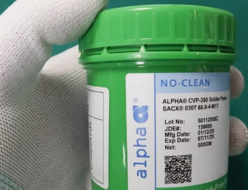
Step 1: Solder Paste Application
The assembly process starts by depositing solder paste which contains small essence patches of drum tableware and bobby alongside flux — onto the solder pads of the circuit board. The pristine- sword stencil deposited above the board directs solder paste to precise element placement locales.
Step 2: Component Placement
Automated pick- and- place equipment uses vacuum snoots to pick up factors similar as resistors, capacitors, and ICs also directly positions them on the solder paste. These machines move at inconceivable pets to place thousands of factors per hour with perfect delicacy. Through-hole components which have leads that penetrate the board need either manual placement or selective placement techniques.
Step 3: Reflow Soldering
As the board enters the reflow oven it goes through multiple heating phases which melt the solder paste thereby attaching components to the board. The oven maintains a precise temperature pattern to protect sensitive parts from damage during the reflow process. Double-sided boards require a second reflow soldering process to complete the opposite side.
Step 4: Through-Hole Soldering (if needed)
Wave soldering is frequently employed to solder through-hole components. The board passes through molten solder that covers the component leads protruding through the board holes. Hand soldering remains the choice for delicate tasks or low-volume assembly despite its slower pace.
Step 5: Inspection and Testing
Quality is everything. Automated Optical Inspection (AOI) machines examine the board for errors in soldering as well as misplaced components and missing parts. X-ray inspection methods are suitable for evaluating internal connections beneath Ball Grid Array (BGA) chips. The next step involves functional testing which requires powering on the board to verify correct operation.
Step 6: Cleaning and Finishing
To avoid corrosion water or specialized solutions remove flux residue left from the soldering process. The board receives conformal coating (a protective layer) or it gets assembled into its final enclosure based on the project requirements.
Step 7: Packaging and Shipping
After testing and cleaning the boards they are placed in anti-static bags to ensure protection during shipping. Your devices such as smartwatches or satellites are now powered and ready for operation.
PCBandAssembly stands out as a reliable partner for bringing PCB manufacturing to reality. A company based in China provides comprehensive solutions covering both fabrication and assembly phases while prioritizing quality and cost-effectiveness. The intuitive platform provided by PCBandAssembly enables users to upload designs, receive immediate pricing estimates and monitor order progress while serving both small startups and big companies.

Get Quote Free