Rogers RO3003 PCB: Complete Guide to Properties, Design & Applications
Rogers RO3003 high frequency laminates are ceramic-filled PTFE composites for use in printed circuit boards in commercial microwave and RF applications. Rogers RO3003 is a high-frequency PCB substrate designed for applications requiring stable electrical performance, low loss, and excellent performance.
Get Your PCB Quote!
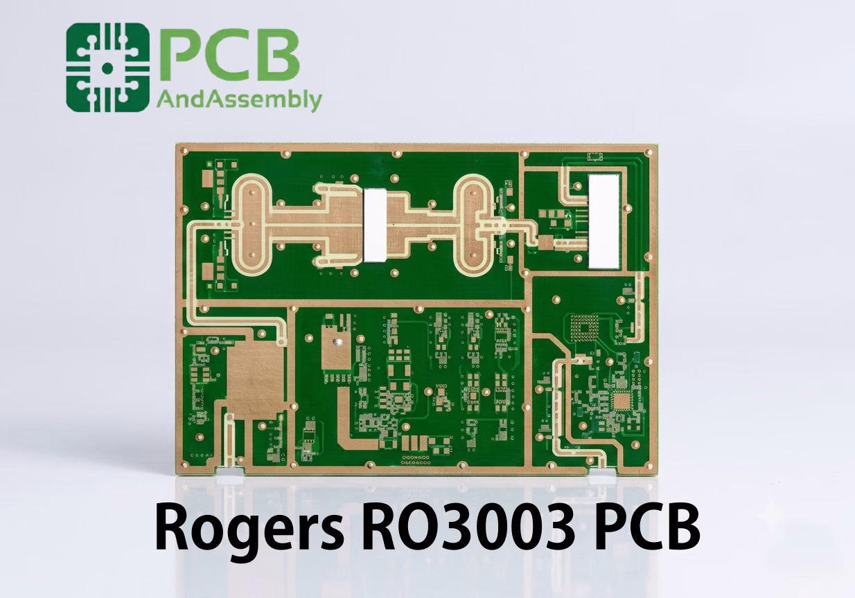
Table of Contents
Table of Contents
If you’re designing circuits for 77 GHz automotive radar, 5G mmWave infrastructure, or any high-frequency system where signal integrity is non-negotiable, you’ve probably felt the limits of standard PCB materials. The dielectric losses climb, impedance control becomes a guessing game, and your simulated performance diverges from reality faster than you can say “FR-4.” That’s where the Rogers RO3003 PCB material enters the picture.
Rogers Corporation developed the RO3000® series specifically for engineers who need predictable, repeatable performance at microwave and millimeter-wave frequencies. The RO3003 sits at the heart of this family—a ceramic-filled PTFE composite that delivers the lowest dissipation factor in the RO3000 lineup while maintaining excellent mechanical stability.
This guide covers everything you need to know about RO3003: the technical specifications that matter, how it compares to other materials, design guidelines for your next project, and real-world fabrication considerations.
Need PCB Manufacturing or Assembly?
Get a free quote within 24 hours. We specialize in prototype-to-production PCB/PCBA for hardware teams worldwide.
What is Rogers RO3003?
RO3003 is a ceramic-filled PTFE (polytetrafluoroethylene) composite laminate designed for high-frequency circuit applications. Unlike woven glass reinforced materials, RO3003 uses a proprietary filler system that provides isotropic electrical properties—meaning its dielectric constant remains consistent regardless of signal propagation direction.
The material belongs to Rogers’ RO3000 series, a family of high-frequency laminates that share similar construction but differ in their dielectric constant values. The “3” in RO3003 refers to its dielectric constant of 3.00, making it the lowest-Dk option in the standard RO3000 lineup (compared to RO3006 at 6.15 and RO3010 at 10.2).
What sets RO3003 apart from other high-frequency materials is its combination of extremely low loss (Df of 0.0010 at 10 GHz) and excellent mechanical stability. The ceramic filler provides a coefficient of thermal expansion closely mached to copper, which means your plated through-holes survive thermal cycling without cracking.
Key Features at a Glance
- Dielectric Constant (Dk): 3.00 ± 0.04 at 10 GHz
- Dissipation Factor (Df): 0.0010 at 10 GHz
- CTE Match to Copper: X/Y axis CTE of approximately 17 ppm/°C (close to copper’s 17 ppm/°C)
- Thermal Conductivity: 0.50 W/m/K
- Water Absorption: 0.04% — excellent for humid environments
- Flammability Rating: UL 94 V-0
RO3003 Electrical Properties
The electrical specifications tell the real story about this material. Here’s what the datasheet data reveals for practical engineering use.
Key Electrical Specifications
| Property | Value | Test Condition | Test Method |
| Dielectric Constant (Dk) | 3.00 ± 0.04 | 10 GHz, 23°C | IPC-TM-650 2.5.5.5 |
| Dissipation Factor (Df) | 0.0010 | 10 GHz, 23°C | IPC-TM-650 2.5.5.5 |
| Design Dk | 3.00 | 10 GHz | Process Specification |
| TCDk (Temperature Coefficient) | -12 ppm/°C | -50°C to 150°C | — |
| Volume Resistivity | 10⁷ MΩ·cm | C96/35/90 | IPC-TM-650 2.5.17.1 |
| Surface Resistivity | 10⁷ MΩ | C96/35/90 | IPC-TM-650 2.5.17.1 |
The dielectric constant of 3.00 provides an excellent middle ground for RF design. It’s low enough to enable wider trace widths for a given impedance (reducing conductor losses) while being high enough to maintain reasonable line lengths for matching networks and filter structures.
The dissipation factor of 0.0010 is remarkable—it’s among the lowest available in ceramic-filled PTFE materials. This Df value means RO3003 maintains useful performance well into the millimeter-wave range, with practical designs operating at frequencies up to 77 GHz and beyond.
Temperature and Frequency Stability
One of RO3003’s strongest characteristics is its stable dielectric constant across both temperature and frequency. The temperature coefficient of Dk is only -12 ppm/°C, meaning a 100°C temperature swing shifts the Dk by roughly 0.1%. For comparison, standard FR-4 can shift by 10% or more over the same range.
| Parameter | RO3003 | Standard FR-4 |
| Dk Variation over -50°C to 150°C | ±0.05 max | ±0.5 or more |
| Dk Variation from 1 GHz to 40 GHz | <1% | >10% |
| Df Variation with Temperature | Minimal | Significant |
This stability is critical for automotive radar and other safety-critical applications. A radar system that drifts out of calibration at high temperature isn’t just a performance issue—it’s a safety hazard.
RO3003 Mechanical and Thermal Properties
Good RF performance means nothing if the board falls apart during assembly or fails in the field. Here’s how RO3003 holds up mechanically and thermally.
Mechanical Specifications
| Property | Value | Direction | Test Method |
| Tensile Modulus | 380 MPa | X | ASTM D638 |
| Tensile Strength | 6.9 MPa | X | ASTM D638 |
| Flexural Modulus | 690 MPa | — | ASTM D790 |
| Flexural Strength | 14 MPa | — | ASTM D790 |
| Specific Gravity | 2.1 | — | ASTM D792 |
| Copper Peel Strength | 10.5 N/mm | 1 oz ED | IPC-TM-650 2.4.8 |
Thermal Specifications
| Property | Value | Test Method |
| CTE (X-axis) | 17 ppm/°C | ASTM E831 / IPC-TM-650 2.4.41 |
| CTE (Y-axis) | 16 ppm/°C | ASTM E831 / IPC-TM-650 2.4.41 |
| CTE (Z-axis) | 25 ppm/°C | ASTM E831 / IPC-TM-650 2.4.41 |
| Thermal Conductivity | 0.50 W/m/K | ASTM D5470 |
| Td (Decomposition Temperature) | >500°C | TGA |
| Water Absorption | 0.04% | IPC-TM-650 2.6.2.1 |
The X/Y CTE values of 17 and 16 ppm/°C are remarkably close to copper’s CTE of approximately 17 ppm/°C. This match is one of the material’s most valuable features—it means the copper traces and the substrate expand and contract at nearly the same rate during thermal cycling, dramatically reducing stress on plated through-holes.
Water absorption of only 0.04% ensures stable electrical performance even in high-humidity environments. For outdoor installations like base station antennas or satellite terminals, this characteristic alone can justify selecting RO3003 over materials with higher moisture sensitivity.
RO3003 Available Configurations
Rogers supplies RO3003 in multiple thicknesses and cladding options to suit different design requirements.
Standard Dielectric Thicknesses
| Thickness (inch) | Thickness (mm) | Tolerance |
| 0.005 | 0.13 | ±0.0005″ |
| 0.010 | 0.25 | ±0.0007″ |
| 0.020 | 0.51 | ±0.0015″ |
| 0.030 | 0.76 | ±0.0020″ |
| 0.060 | 1.52 | ±0.0030″ |
Copper Cladding Options
RO3003 is available with several copper foil configurations:
Electrodeposited (ED) Copper: Standard offering in ½ oz (17 μm), 1 oz (35 μm), and 2 oz (70 μm) weights. ED copper provides reliable adhesion and is suitable for most applications.
Reverse Treated ED Copper: Offers enhanced adhesion to the PTFE substrate while maintaining good electrical performance. Recommended for multilayer constructions.
Thick Metal Cladding: For specialized applications, RO3003 can be supplied with thick aluminum, copper, or brass claddings. These options provide integrated heat sinking for high-power designs.
Standard Panel Sizes
Panels are typically available in 12″ × 18″ (305 × 457 mm) and 24″ × 18″ (610 × 457 mm). Custom sizes may be available through authorized distributors.
RO3003 vs RO3006 vs RO3010: Choosing the Right Material
The RO3000 series spans a range of dielectric constants to support different design requirements. Here’s how the three main variants compare.
| Property | RO3003 | RO3006 | RO3010 |
| Dielectric Constant (Dk) | 3.00 ± 0.04 | 6.15 ± 0.15 | 10.2 ± 0.30 |
| Dissipation Factor (Df) | 0.0010 | 0.0020 | 0.0022 |
| — | — | — | — |
| Thermal Conductivity (W/m/K) | 0.50 | 0.50 | TBD |
| CTE Z-axis (ppm/°C) | 25 | 24 | 17 |
| Water Absorption (%) | 0.04 | 0.02 | 0.05 |
| — | — | — | — |
| Typical Application | Low-loss RF, mmWave | Antennas, power amps | High-Dk circuits |
When to Choose RO3003
Select RO3003 when you need the lowest possible losses in the RO3000 family. It’s the best choice for:
- Circuits operating above 20 GHz where every tenth of a dB matters
- Automotive radar at 77 GHz
- Low-noise amplifiers and receiver front-ends
- Applications requiring tight Dk tolerance (±0.04)
When to Choose RO3006
RO3006 offers a Dk of 6.15, which enables circuit size reduction compared to RO3003. Use it for:
- Antenna elements where smaller patch sizes are beneficial
- Power amplifier matching networks
- Size-constrained designs where wavelength reduction matters
When to Choose RO3010
RO3010’s Dk of 10.2 provides maximum circuit miniaturization. It’s suitable for:
- High-impedance bias lines
- Decoupling networks
- Applications where space is at a premium and loss is secondary
RO3003 vs FR-4: Why the Premium Is Worth It
The cost difference between RO3003 and standard FR-4 can be significant. Understanding where that money goes helps justify the investment.
| Property | RO3003 | Standard FR-4 |
| Dk at 10 GHz | 3.00 ± 0.04 | 4.2-4.8 ± 10% |
| Df at 10 GHz | 0.0010 | 0.020-0.025 |
| Dk Stability vs Frequency | Excellent | Poor above 1 GHz |
| CTE Z-axis (ppm/°C) | 25 | 60-70 |
| Moisture Absorption | 0.04% | 0.1-0.3% |
| Maximum Usable Frequency | 77+ GHz | ~2 GHz |
| PTH Reliability | Excellent | Moderate |
At 10 GHz, FR-4’s dissipation factor is roughly 20-25 times higher than RO3003’s. This means your signals will experience dramatically higher insertion loss on FR-4. A 10 cm microstrip line that loses 0.5 dB on RO3003 might lose 10+ dB on FR-4 at the same frequency—the difference between a functional circuit and one that simply doesn’t work.
Below 1-2 GHz, FR-4 remains a sensible and cost-effective choice when loss isn’t critical. Above that frequency range, materials like RO3003 become a requirement rather than a luxury.
RO3003 PCB Design Guidelines
Designing with RO3003 requires an understanding of its unique characteristics. Here are practical guidelines based on real-world engineering.
Impedance Control
The Dk of 3.00 results in wider traces for a given characteristic impedance compared to higher-Dk materials. For 50 Ω microstrip on a 10 mil (0.010″) substrate, expect trace widths around 20-22 mils—significantly wider than the 10-12 mils you’d use on FR-4.
Design Tip: Use the Design Dk of 3.00 as your starting point for impedance calculations. Work with your fabricator to correlate theoretical values with actual measured impedances from coupon testing.
Trace Width Reference
| Target Impedance | Substrate Thickness | Approximate Trace Width (50 Ω) |
| 50 Ω microstrip | 5 mil (0.13 mm) | ~11 mil |
| 50 Ω microstrip | 10 mil (0.25 mm) | ~21 mil |
| 50 Ω microstrip | 20 mil (0.51 mm) | ~42 mil |
| 50 Ω stripline | 10 mil total | ~8 mil |
*Values are approximate and depend on copper thickness and solder mask effects.
Via Design for Reliability
The Z-axis CTE of 25 ppm/°C provides excellent PTH reliability, but proper via design is still essential:
- Keep aspect ratios below 10:1 for standard processing
- Use minimum annular rings of 5 mils
- Specify adequate copper plating thickness (1.0-1.2 mils minimum)
- Consider back-drilling for signal vias carrying high-frequency signals
Thermal Management
RO3003’s thermal conductivity of 0.50 W/m/K is approximately double that of standard FR-4. This helps dissipate heat from power-hungry components, but additional thermal management is still needed for high-power designs:
- Use thermal via arrays under power devices
- Maximize copper pours on inner layers for heat spreading
- For extreme thermal requirements, consider RO3003 with thick metal cladding options
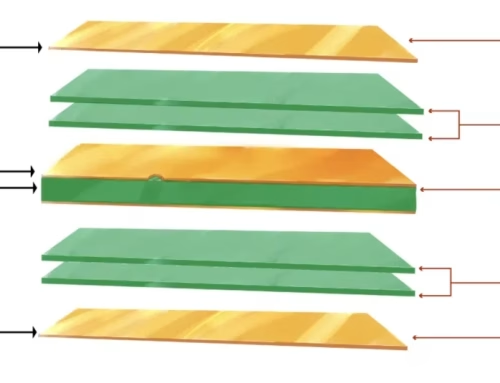
Multilayer Stackup Considerations
For multilayer designs using RO3003, Rogers recommends compatible bonding materials from the RO4000® series. RO4450F or RO4450T prepregs provide matched electrical and thermal properties for hybrid stackups.
| Layer | Material | Typical Thickness |
| Outer signal | RO3003 or RO4003C | 10-20 mil |
| Bonding | RO4450F prepreg | 2-4 mil |
| Inner signal | RO3003 | 5-10 mil |
| Core | RO3003 | 20-30 mil |
| Inner ground | RO3003 | 5-10 mil |
| Bonding | RO4450F prepreg | 2-4 mil |
| Outer signal | RO3003 | 10-20 mil |
RO3003 PCB Fabrication Guidelines
PTFE-based materials require different fabrication approaches than standard FR-4. Here’s what manufacturers need to know.
Drilling Parameters
| Parameter | Recommendation |
| Drill Material | Carbide, 130° included lip angle |
| Surface Speed | 150-250 SFM (45-75 m/min) |
| Chip Load | 0.001-0.002″ per revolution |
| Maximum Stack Height | 0.240″ (6.1 mm) |
| Drill Condition | New or precision-ground |
PTFE materials are prone to smear during drilling. Plasma desmear or sodium-based chemical treatment is essential before electroless copper plating to ensure reliable through-hole connections.
Etching Considerations
RO3003 etches well using standard PCB etching chemistries:
- Etchants: Ferric chloride, ammonimum persulfate, or cupric chloride
- Etch Factors: 1.5-2.0 for 1 oz copper
- Rinse: Thorough DI water rinse to remove chemical residues
Surface Preparation for Plating
PTFE does not naturally accept metal deposition. Surface treatment options include:
Sodium Etchant: Creates a chemically reactive surface for electroless copper adhesion. Products like Tetra-Etch are commonly used in PCB fabrication.
Plasma Treatment: Uses H₂/N₂ or NH₃ gas plasma to modify the surface chemistry. This method is preferred for direct metallization processes and avoids the handling concerns of sodium etchants.
Compatible Surface Finishes
RO3003 PCB supports all standard surface finishes:
- HASL (Hot Air Solder Leveling)
- ENIG (Electroless Nickel Immersion Gold)
- Immersion Tin
- Immersion Silver
- OSP (Organic Solderability Preservative)
For high-frequency applications above 10 GHz, ENIG or immersion silver typically provides the best performance due to their smooth surface profiles. Rough finishes increase conductor losses at high frequencies where skin effect concentrates current at the trace surface.
Lead-Free Assembly
RO3003’s decomposition temperature exceeds 500°C, providing ample margin for lead-free soldering profiles with peak temperatures of 260°C. The material is fully compatible with RoHS-compliant assembly processes.
RO3003 PCB Applications
RO3003’s combination of low loss, stable Dk, and excellent thermal properties makes it the material of choice for demanding applications across multiple industries.
Automotive Radar (77 GHz)
Modern vehicles rely on radar sensors for adaptive cruise control, automatic emergency braking, and blind-spot monitoring. These systems operate at 77 GHz (long-range) and 79 GHz (short-range), frequencies where material losses dominate system performance.
RO3003 is one of the most widely used laminates for automotive radar because:
- The Df of 0.0010 ensures acceptable signal levels at 77 GHz
- Stable Dk across temperature prevents range measurement drift
- Low water absorption maintains performance through weather exposure
- CTE match to copper ensures PTH reliability under hood-temperature cycling
5G and mmWave Infrastructure
5G networks operating at 28 GHz, 39 GHz, and millimeter-wave frequencies above 24 GHz demand PCB materials that can deliver consistent performance. Base station antennas, particularly massive MIMO arrays, benefit from RO3003’s tight Dk tolerance of ±0.04.
When you’re building an antenna array with 64 or more elements, material consistency directly affects beam-forming accuracy. RO3003’s batch-to-batch uniformity helps ensure that every antenna element performs identically.
Point-to-Point Backhaul Radios
Backhaul links operating at 18 GHz to 80 GHz require low-loss substrates to maintain adequate link budgets over distances of several kilometers. Every 0.5 dB of additional PCB loss translates directly to reduced distance or lower data rates. RO3003’s dissipation factor of 0.0010 minimizes this loss contribution.
Aerospace and Defense
Military radar, electronic warfare systems, and satellite communications all benefit from RO3003’s properties:
- Phased array radar systems
- Missile guidance electronics
- Satellite communication terminals
- Wideband receivers and transmitters
The material’s stability under temperature extremes and resistance to moisture absorption make it suitable for the demanding environments these systems operate in.
Test and Measurement Equipment
RF test equipment demands materials with precisely known and stable properties. RO3003 is used in:
- Calibration standards and reference planes
- High-frequency probe cards
- Test fixtures for mmWave device characterization
- Vector network analyzer calibration kits
Thermal Management Strategies
While RO3003’s thermal conductivity of 0.50 W/m/K outperforms FR-4, power amplifier and other high-dissipation designs require additional thermal management.
Heat Spreading Techniques
- Thermal Via Arrays: Place grids of plated vias under heat-generating components to conduct heat to inner ground planes. For a 4×4 array of 12 mil vias, expect a thermal resistance reduction of approximately 80% compared to bare laminate.
- Copper Pour Maximization: Use maximum copper fill on all available layers beneath hot components. Thicker copper (2 oz) on inner planes improves lateral heat spreading.
- Thick Metal Cladding: Rogers offers RO3003 with thick aluminum or copper cladding for extreme thermal requirements. This option integrates the heat sink directly into the substrate.
Temperature-Dependent Dk Compensation
For precision applications, account for Dk shift with temperature:
- TCDk: -12 ppm/°C
- Over a 125°C range (-40°C to +85°C typical automotive), expect approximately 0.15% Dk shift
- This translates to roughly 0.07% impedance variation—negligible for most applications
How to Order RO3003 Laminates
When specifying RO3003 for your project, include these parameters in your fabrication documentation:
- Dielectric thickness and tolerance
- Copper type: ED, reverse treated, or thick metal cladding
- Copper weight: ½ oz, 1 oz, or 2 oz
- Panel size requirements
- Any special processing requirements
Typical Lead Times and Costs
For prototype quantities (1-10 panels), expect lead times of 2-4 weeks through authorized distributors. Production volumes typically run 4-6 weeks. Cost runs approximately $120-200 per square foot depending on thickness and copper configuration—roughly 5-10 times standard FR-4 pricing, but significantly less than pure PTFE alternatives.
Sourcing Notes
Most designers work through PCB fabricators who maintain relationships with Rogers distributors. When requesting quotes:
- Specify RO3003 by name in your fabrication drawing
- Include the required thickness (10 mil, 20 mil, etc.)
- Note if you need low-profile copper for high-frequency applications
- Ask about lead times for your specific configuration
Standard configurations (10 mil and 20 mil cores with 1 oz copper) typically have the best availability. Custom thicknesses or metal cladding options may require longer lead times.
If you need a reliable partner for RO3003 PCB fabrication, PCBAndAssembly specializes in high-frequency PCB manufacturing with experience processing Rogers RO3000 series materials. Contact us with your stackup requirements and target impedance specifications for a detailed review.
Useful Resources
Here are authoritative sources for RO3003 technical information:
Official Rogers Documentation
- RO3000 Series Data Sheet: Rogers Corporation website
- Fabrication Guidelines for RO3000 Laminates: Available from Rogers
- Rogers MWI-2017 Impedance Calculator: Free online design tool
Design Tools
- Rogers MWI-2017: Microwave impedance calculator with loss estimation
- Rogers TDDK Calculator: Temperature-dependent Dk modeling tool
- Rogers Laminates Properties Tool: Material selector and property comparison
Technical Support
Rogers Corporation offers application engineering support for complex RO3003 designs. Contact them through their website for assistance with challenging multilayer or high-frequency applications.
Frequently Asked Questions About RO3003 PCB
What is the maximum operating frequency for RO3003 PCB?
RO3003 performs well through the full microwave range and into millimeter-wave frequencies. Practical designs operate successfully at 77 GHz (automotive radar) and beyond. The dissipation factor of 0.0010 at 10 GHz maintains acceptable losses even at 100+ GHz, though conductor losses become increasingly significant above 40 GHz.
Can RO3003 be used for multilayer PCB construction?
Yes, RO3003 supports multilayer construction using Rogers’ compatible bonding materials. RO4450F and RO4450T prepregs provide matched electrical and thermal properties for hybrid stackups. Fusion bonding techniques can also be used to create monolithic multilayer structures without adhesive layers.
How does RO3003 compare to PTFE materials like RT/duroid?
RO3003 offers several advantages over woven glass reinforced PTFE materials. The ceramic-filled construction provides a much closer CTE match to copper (25 ppm/°C Z-axis vs. 173 ppm/°C for RT/duroid 5870), significantly improving PTH reliability. RO3003 also maintains more consistent electrical properties without the fiber weave effect that can plague woven glass materials at mmWave frequencies.
Is RO3003 compatible with standard PCB fabrication processes?
RO3003 can be processed using standard PCB fabrication equipment, but PTFE-based materials require modified procedures. Key differences include the need for surface treatment before plating (sodium etch or plasma), specific drilling parameters to minimize smear, and careful handling of the relatively soft material. Fabricators experienced with high-frequency materials typically achieve good results without major equipment changes.
What surface finishes work best for high-frequency RO3003 PCB applications?
ENIG and immersion silver provide the smoothest surfaces, minimizing conductor losses at high frequencies where skin effect concentrates current at the trace surface. HASL creates rougher surfaces that can increase losses above 10 GHz. For millimeter-wave designs, smooth finishes become critical to overall performance.
Can RO3003 withstand lead-free assembly temperatures?
Yes. RO3003’s decomposition temperature exceeds 500°C, providing ample margin for lead-free soldering profiles with peak temperatures of 260°C. The material is fully compatible with RoHS-compliant assembly processes and multiple reflow cycles.
What is the recommended storage and handling for RO3003 laminates?
Store RO3003 laminates in a clean, dry environment at temperatures between 10°C and 40°C (50°F to 104°F). Keep the material in its original packaging until ready for use. The material’s low water absorption (0.04%) means pre-baking before assembly is typically unnecessary, but follow your fabricator’s recommendations for specific process requirements.
How does RO3003 handle vibration and mechanical shock?
RO3003’s ceramic-filled PTFE construction provides good mechanical damping characteristics. The material has been qualified for automotive applications where vibration resistance is critical. For extreme vibration environments, consider appropriate mechanical support and conformal coating for assembled boards.
Conclusion
Rogers RO3003 PCB laminate represents a carefully engineered solution for the most demanding high-frequency applications. Its combination of extremely low loss, excellent thermal properties, stable CTE matching to copper, and tight Dk tolerance makes it a top choice for automotive radar, 5G infrastructure, aerospace systems, and mmWave communications.
The material’s versatility across different thicknesses and cladding options means you can use it for everything from simple two-layer antenna boards to complex multilayer mixed-material stackups. When paired with compatible bonding materials like RO4450F prepreg, RO3003 enables reliable high-performance designs that maintain their specifications across temperature extremes and years of service.
For your next high-frequency PCB project, RO3003 deserves serious consideration—especially if your design operates above 10 GHz, requires stable performance across temperature, or needs reliable PTH construction. Work with an experienced fabricator who understands PTFE processing, and you’ll have a solid foundation for circuits that perform as designed, every time.

Get Quote Free