Hot-Swap PCB Design Guide: Sockets, Compatibility, and Reliability
This guide breaks down what actually determines hot swap PCB reliability, how different socket types compare on real engineering metrics, and what to look for when choosing a PCB — whether you are building your first custom board or designing one for production.
Get Your PCB Quote!
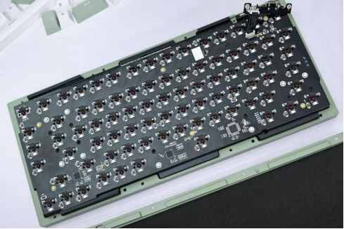
Table of Contents
- Quick Specs
- What is a hot swap PCB?
- What’s commonly misunderstood about hot swap PCBs
- Hot swap socket types compared
- PCB design considerations for hot swap sockets
- Socket quality and durability across the supply chain
- QMK and VIA: the software side of hot swap
- Common hot swap PCB failure modes
- Why hot swap PCBs matter for prototype and production
- Frequently asked questions
- Useful resources
- Conclusion
Table of Contents
- Quick Specs
- What is a hot swap PCB?
- What’s commonly misunderstood about hot swap PCBs
- Hot swap socket types compared
- PCB design considerations for hot swap sockets
- Socket quality and durability across the supply chain
- QMK and VIA: the software side of hot swap
- Common hot swap PCB failure modes
- Why hot swap PCBs matter for prototype and production
- Frequently asked questions
- Useful resources
- Conclusion
Quick Specs
| Socket types | Kailh CPG (SMT), Gateron (SMT), Outemu (SMT), Mill-Max (through-hole) |
| Standard MX pin pitch | 19.05 mm (0.75 in) switch grid |
| Switch pin diameter | Model and switch specific; verify manufacturer drawings |
| SMT socket rated cycles | Model-specific; classic Kailh CPG: 100; verify exact model |
| Mill-Max rated cycles | Model-specific; verify exact part and test conditions |
| Governing PCB standards | IPC-2221C (general design), IPC-6012F (bare-board qualification) |
| Typical layer count | 2 layers (standard); 4 layers (split spacebar, in-switch RGB, per-key LEDs) |
| Typical PCB thickness | 1.2 mm or 1.6 mm (standard keyboard thicknesses) |
| Surface finish preference | ENIG often preferred; qualify the selected finish and process |
A hot swap PCB is a mechanical keyboard circuit board fitted with specialized sockets at each switch position that allow a user to insert and remove mechanical switches without soldering — a plug-and-play interface that transforms a keyboard from a fixed peripheral into a modular, reconfigurable system. The underlying technology is straightforward: each switch position uses either a surface-mount leaf-spring socket or a through-hole cylindrical socket to grip the switch pins, replacing the permanent solder joint with a mechanical clamp. What separates a reliable hot swap keyboard from a frustrating one comes down to three things that most buying guides never mention: the socket type and its actual cycle rating, the PCB’s plating quality and pad design, and the dimensional tolerances between the socket and the switch pins.
Most guides treat all hot-swap PCBs as equivalent, but reliability depends on the socket model, footprint, surface finish, solder process, plate support, and user technique.
Key Takeaways
- Hot swap sockets are not universal: Kailh CPG, Gateron, Outemu, and Mill-Max use different mounting methods and pin-opening sizes, and cross-compatibility is narrower than most buyers assume.
- Socket life is model-specific: the classic Kailh CPG socket is specified for 100 replacement cycles, while newer products can have different ratings. Always check the exact socket datasheet rather than applying one number to every SMT socket.
- Mill-Max through-hole sockets offer a rated 1,000+ insertion cycles but require manual soldering onto a standard PCB, meaning they are an enthusiast mod, not a factory-ready solution.
- ENIG is often preferred for SMT hot-swap footprints because its surface is flat and uniform. HASL may also be suitable when the socket footprint, soldering process, and pad strength have been qualified.
- PCB plating quality and pad adhesion, not just the socket brand, determine whether a hot swap board survives to its rated cycle count — a well-designed footprint on a properly plated 2-layer board outperforms a premium socket on a poorly plated one.
What is a hot swap PCB?
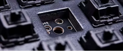
A hot swap PCB replaces traditional through-hole solder pads with spring-loaded receptacles at each switch position. Instead of permanently attaching a switch by melting solder through the joint, the switch pins are held in place by mechanical friction inside the socket’s contact leaf. This means a user can change switches as often as they like — within the socket’s rated cycle count — without ever touching a soldering iron.
The mechanism is deceptively simple. An SMT hot swap socket is a small surface-mount component with two leaf-spring channels that align with the switch’s two electrical pins (plus a third channel for the plastic alignment pin on 5-pin switches). When a switch is pressed into place, the pins slide between the spring leaves, which exert enough lateral force to maintain electrical contact under normal typing forces. Removing the switch with a dedicated puller reverses the process — the spring leaves release the pins without permanent deformation, assuming the pins were straight and the socket was not damaged during insertion.
Through-hole conversion sockets like Mill-Max operate on the same principle but are installed into existing switch holes on a standard PCB and then soldered in place. They effectively convert a non-hot-swap PCB into a hot-swap one, but require soldering skill to install.
What’s commonly misunderstood about hot swap PCBs
The most persistent misconception is that any hot swap socket accepts any MX-style switch. In practice, there are three compatibility boundaries that matter:
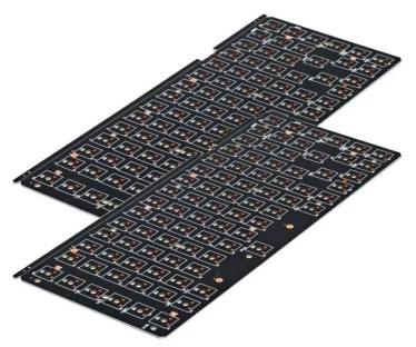
- Pin diameter tolerance.Standard Cherry MX and Gateron pins measure 0.95–1.05 mm. Outemu sockets use a narrower leaf-spring opening that accommodates Outemu’s 1.0 mm pins but deforms permanently when forced with a 1.2 mm pin from a budget clone switch. Once the spring is over-opened, the socket cannot generate enough contact force to maintain a reliable connection — intermittent keystrokes or ghosting appear within weeks.
- Socket mounting method. SMT sockets are designed for a specific surface-mount footprint and assembly process. Through-hole sockets such as Mill-Max use plated holes and soldering. These approaches are not interchangeable, so verify the socket footprint before ordering the PCB.
- 3-pin vs. 5-pin compatibility.Most modern hot swap sockets support both 3-pin and 5-pin MX-style switches. The two plastic alignment pins on a 5-pin switch (also called PCB-mount switches) pass through dedicated holes in the PCB. If a PCB lacks these alignment holes, 5-pin switches can still be used by clipping the plastic pins off — but this introduces mechanical instability during insertion and removal, and is one of the most common sources of bent pins when a user tries to seat the switch without the alignment guides.
📐 Engineering Note
A switch pin outside the socket manufacturer’s specified geometry can reduce contact margin, deform the spring, or prevent reliable seating. The effect depends on contact shape, material, plating, and insertion angle. Use the exact socket drawing and switch drawing when compatibility matters; do not apply a generic percentage to contact-force loss.
Hot swap socket types compared
The major socket families differ in mounting method, documented life rating, compatibility profile, and assembly requirements. Compare like-for-like part numbers because a product family may contain several generations and footprints.
| Socket Type | Mounting Method | Manufacturer Rated Cycles | Typical Pin Dia. Range | Switch Cross-Compatibility | Surface Finish Preference | Quote-dependent |
| Kailh CPG | SMT (reflow) | Kailh CPG: 100; other models differ | Model and switch specific; verify manufacturer drawings | Verify exact model and target switches | ENIG preferred | Quote-dependent |
| Gateron | SMT (reflow) | Model-specific; Gateron Hot-Swap 2.0 is published as >50,000 cycles | Model and switch specific; verify manufacturer drawings | Confirm exact model and target switches | ENIG preferred | Quote-dependent |
| Outemu | SMT (reflow) | Model-specific; verify datasheet | Model and switch specific; verify manufacturer drawings | May have a narrower compatibility window | ENIG preferred | Quote-dependent |
| Mill-Max 7305 | Through-hole (solder) | Model-specific; verify datasheet | Model and switch specific; verify manufacturer drawings | Confirm exact part and finished-hole size | Standard ENIG or HASL | Quote-dependent |
| Holtite | Through-hole (press) | Model-specific; verify datasheet | Model and switch specific; verify manufacturer drawings | Most MX-style pressure-fit (no solder) | Depends on model and hole finish | Quote-dependent |
Cycle ratings must be tied to a specific part number and test method. The classic Kailh CPG specification lists 100 replacement cycles. Gateron has published different ratings for different socket generations, including a Hot-Swap 2.0 product described as exceeding 50,000 life cycles. These figures are manufacturer test results, not a universal field-life guarantee. Actual results depend on straight switch pins, insertion angle, mechanical support from the plate, and the quality of the soldered pad.
PCB design considerations for hot swap sockets
A hot swap PCB places different demands on PCB fabrication than a standard soldered keyboard PCB. Three areas determine whether the board survives repeated switch swapping.
Pad design and adhesion
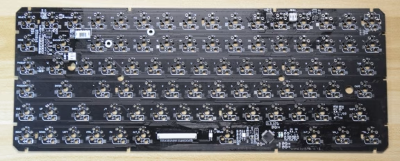
SMT hot swap sockets solder onto flat surface-mount pads, not through-hole pads. The socket’s metal contact legs are small — typically 2–3 mm long — which means the solder fillet area is correspondingly small. If the pad does not have adequate copper-to-substrate adhesion, the repeated mechanical stress of inserting and removing switches will lift the pad off the board entirely.
ENIG is commonly preferred for SMT hot-swap sockets because it provides a relatively flat and uniform solderable surface. HASL is not automatically unsuitable, but the fabricator should verify pad coplanarity, stencil printing, reflow, solder coverage, and mechanical support. Surface finish alone does not determine whether a pad will lift.
📐 Engineering Note
Pad adhesion is important, but a board-level peel-strength result should not be converted directly into the pull-off force of one small SMT pad. Ask the fabricator how pad geometry, copper construction, solder coverage, reflow profile, and mechanical support are qualified for the selected socket. If a design uses a plate that supports switch insertion, include that mechanical stack-up in the review.
Plating thickness and via reliability
Hot-swap PCBs often include per-key LEDs and vias near the switch sockets. Repeated insertion and removal can load the socket, solder joint, pad, and nearby copper features. Via reliability should be specified against the applicable IPC-6012 revision, board class, and construction. Do not claim that a particular number of switch swaps will create barrel cracks without a controlled test; review annular geometry, hole quality, copper plating, board support, and the location of vias near the socket footprint.
Hole sizing for through-hole conversion
Mill-Max socket installation depends on the exact socket part number, lead length, and PCB footprint. A conversion design should specify the finished hole diameter from the manufacturer’s drawing before fabrication. Do not re-drill a populated PCB, and do not assume that a standard switch hole will accept every Mill-Max variant.
Socket quality and durability across the supply chain
Sockets from different supply sources should be controlled by approved manufacturer and part number. If alternates are allowed, verify the footprint, contact material, plating, electrical ratings, mechanical life, and incoming-inspection requirements rather than approving an alternate by appearance alone.
A visually similar clone is not automatically an approved alternate. Without a controlled comparison, it is not possible to claim a particular loss of contact force or cycle life. For production keyboards, buy through a traceable supply chain and qualify any alternate socket with dimensional, electrical, solderability, and mechanical-life checks.
QMK and VIA: the software side of hot swap
Hot swap PCBs handle the physical switch swapping, but QMK (Quantum Mechanical Keyboard) firmware and its user-facing interface, VIA, handle the logical layer — key mapping, layers, macros, and per-key RGB control. These are independent capabilities: a PCB can support hot swap without supporting QMK/VIA, but the custom keyboard experience most users expect (freely reassignable keys, multiple layers, rotary encoder support) requires QMK-compatible firmware.
When evaluating a hot swap PCB, QMK/VIA support is not a nice-to-have — it is the feature that turns a board with replaceable switches into a genuinely customizable input device. Without it, you are limited to the factory key layout. With it, every key on the board can be reassigned to any function, across multiple layers, with custom lighting effects, macro sequences, and tap-dance or combos.
A quick decision framework for PCB selection:
| If you want to… | Then prioritize… |
| Try different switch types and brands | Kailh or Gateron SMT sockets, ENIG finish |
| Convert an existing soldered PCB to hot swap | Mill-Max socket selected from the exact part drawing and finished-hole requirement |
| Full remapping, layers, macros | QMK/VIA-compatible PCB (or just QMK if you are comfortable compiling firmware) |
| Pre-built keyboard with basic hot swap only | Outemu or Kailh sockets, pre-QMK firmware |
| Compare exact socket datasheet and test conditions | Mill-Max or Holtite (requires hand soldering) |
| Budget-friendly first build | Gateron SMT sockets on a standard 2-layer board |
Common hot swap PCB failure modes
Hot-swap failures can originate in the socket, solder joint, PCB pad or via, switch pin, plate support, or user technique. The practical failure modes to review are:
- Lifted pads. This can happen when a switch is removed at an angle, the socket is poorly soldered, the pad geometry is too small, or the PCB is not supported by the plate. Prevention: use a proper switch puller, keep the switch vertical during removal, and have the socket footprint and solder process reviewed.
- Bent or damaged socket contacts. A bent switch pin, incompatible pin geometry, or angled insertion can deform the contact. Prevention: inspect pins before insertion and confirm compatibility with the exact socket model.
- Intermittent matrix connections. A cracked via, weak solder joint, damaged socket, or trace stress can create an open circuit that appears only after mechanical movement. Prevention: specify the applicable board-performance requirements and investigate intermittent faults with continuity checks, microscope inspection, and controlled flex or insertion testing.
Experience-backed: what we see in DFM review
In DFM reviews, our engineers often check whether the selected socket footprint actually matches the socket drawing and whether the pad has enough copper area and mechanical support for repeated switch insertion. A footprint copied from another socket model can look correct in CAD while creating weak solder coverage or a poor fit in production. This is why the socket part number, PCB footprint, plate, and assembly process should be reviewed together before tooling.
Why hot swap PCBs matter for prototype and production
Hot-swap capability is now common across many custom and enthusiast keyboard designs. For a PCB supplier, the practical implication is that the socket footprint, plate support, switch compatibility, and test plan should be treated as production requirements rather than as optional features.
For keyboard designers and brand owners, the practical implication is that socket and surface finish choices made at the PCB specification stage determine long-term field reliability. A cost saving of $0.50–1.00 per PCB by switching from ENIG to HASL on a 10,000-unit production run saves $5,000–10,000 upfront — but if it increases the pad-lift failure rate from 0.5% to 5%, the replacement and warranty cost at a typical $80–150 keyboard price point erases the savings many times over. That trade-off is worth calculating in advance, not discovering after field returns start arriving.
📐 Engineering Note
Assume a 10,000-unit production run at $100 MSRP. ENIG vs. HASL incremental cost: approximately $0.75/board. Total ENIG premium: $7,500. If HASL produces a 3% higher pad-lift failure rate (conservative estimate based on manufacturer-return data reported across multiple keyboard brands), that is 300 additional field failures. At a 10% warranty return rate within the first year (a typical figure for mechanical keyboards), 30 units are returned. Each return costs approximately $35 in processing, replacement PCB, and shipping. Warranty cost: 30 × $35 = $1,050. The warranty cost alone does not offset the $7,500 finish premium — but the reputation cost of 30 users receiving replacement keyboards and posting about the failure in enthusiast communities is not captured in this simple model. For a brand targeting the enthusiast market, that reputation cost is the larger figure.
Frequently asked questions
Q: Can any mechanical switch be used with a hot swap PCB?
No. While most hot swap PCBs accept standard 3-pin and 5-pin MX-style switches (Cherry MX, Gateron, Kailh), some budget boards use Outemu sockets that only work reliably with Outemu switches or switches with thin pins. Always check the PCB’s socket type and compare it with your switch’s pin diameter before buying.
Q: How many times can I swap switches before the sockets wear out?
Socket life is part-number specific. The classic Kailh CPG socket is specified for 100 replacement cycles, while other socket generations have different published ratings. Mill-Max life also depends on the exact part and test conditions. Do not present 100 or 1,000+ cycles as a universal guarantee; verify the manufacturer’s drawing and qualify the socket for the intended use.
Q: What surface finish is best for hot swap PCBs?
ENIG is often preferred for SMT hot-swap sockets because it provides a flat, uniform solderable surface. HASL may be suitable when the footprint and process are qualified. The correct choice depends on the board design and assembly controls.
Q: Can I convert a standard soldered PCB to hot swap?
Yes, using Mill-Max 7305 sockets or Holtite press-fit sockets. Mill-Max requires a 1.27 mm drilled hole at each switch position and hand-soldering. Holtite press-fit sockets require no soldering but need ENIG-finished pads and precise hole sizing. Both options require more skill and tools than buying a pre-made hot swap PCB.
Q: Do hot swap PCBs feel different from soldered PCBs?
For most users, there is no perceptible difference in typing feel between a properly installed hot swap switch and a soldered one. Some experienced builders report a slight increase in switch wobble or a marginally softer bottom-out feel on hot swap boards, but these differences are well below the level that affects typing accuracy or sound profile. The switch choice, plate material, and case construction have far larger effects on typing feel than the socket connection itself.
Q: What is the difference between Kailh, Gateron, and Outemu sockets?
Compatibility depends on the exact socket footprint, switch pin geometry, and the manufacturer’s stated compatibility. Kailh-style sockets are widely used, but a buyer should still confirm the part number and target switches. Outemu-compatible designs may have a narrower compatibility window. There is no universally safest socket without knowing the intended switch set and PCB design.
Useful resources
Industry standards referenced
- IPC-2221C: Generic Standard on Printed Board Design. Use the current IPC document and the applicable design details for pad, hole, clearance, and spacing decisions.
- IPC-6012F: Qualification and Performance Specification for Rigid Printed Boards. Confirm the applicable class, construction, and exact acceptance tables before quoting numeric requirements.
- IPC-TM-650 Method 2.4.8: Peel Strength of Copper. Do not use a coupon peel result as a direct prediction of the pull-off force of one finished SMT pad.
Key socket documentation
- Kailh CPG SMT Socket Datasheet — verify the exact part number, footprint, electrical ratings, and replacement-cycle specification.
- Mill-Max 7305 documentation— confirm the exact part number and finished-hole requirements against the manufacturer’s drawing or an authorized distributor’s datasheet.
Conclusion
Hot swap PCBs have shifted from an enthusiast niche to the dominant specification for custom and mid-range mechanical keyboards, driven by their simple promise: change your switches without changing your board. But the reliability of that promise depends on engineering decisions that most buying guides never surface — the socket type and its actual cycle rating, the PCB’s surface finish and plating quality, and the dimensional tolerance stack-up between the socket and the switch pins.
Whether you are a keyboard enthusiast selecting a PCB for your next build or a brand owner specifying fabrication for a production run, prioritize verified socket compatibility, a qualified footprint and solder process, suitable board-performance requirements, and a fabricator that can document inspection and traceability. If you are evaluating PCB fabrication partners for a keyboard production run, our DFM team at OrinewPCB can review your socket footprint, plate interface, and stackup before you commit to tooling.

Get Quote Free