2 oz PCB: Heavy Copper for Power Electronics & High-Current Designs
When your design pushes past the limits of standard 1 oz copper — sustained currents above 3A per trace, thermal hotspots that threaten component life, or operating environments with extreme vibration — you need more copper. The 2 oz PCB (70 µm thick per layer) is the most common "step up" from standard weight, and it solves problems that 1 oz simply cannot.
Get Your PCB Quote!
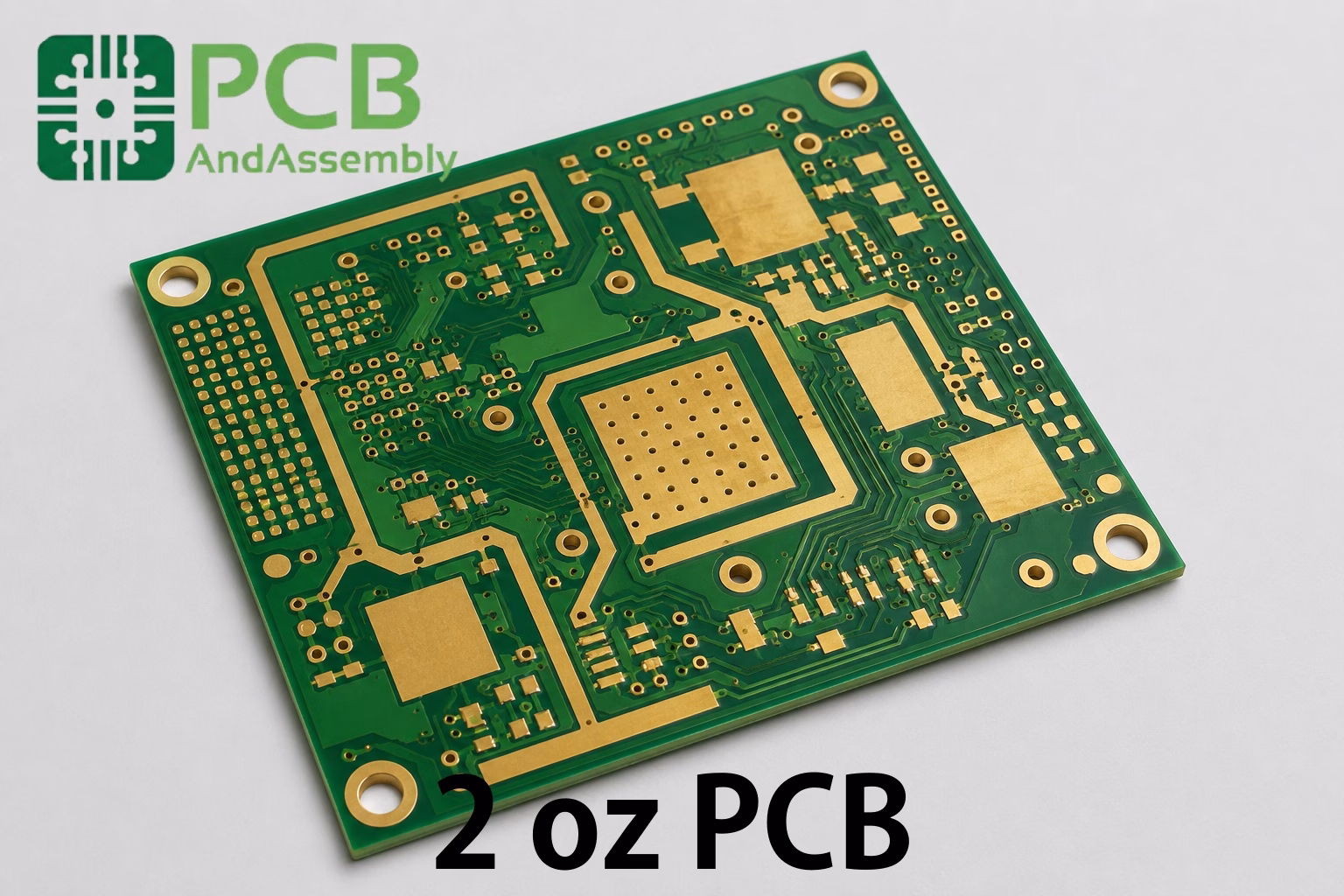
Table of Contents
Table of Contents
Thicker copper means lower resistance, which means less voltage drop, less heat, and more current capacity per trace width. It also provides better thermal spreading and greater mechanical strength at plated through-holes and solder joints. For power supplies, motor controllers, LED driver boards, automotive electronics, and solar inverters, 2 oz copper isn’t a luxury — it’s often the minimum that keeps the design reliable.
What is 2 oz PCB?
A 2 oz PCB uses copper foil weighing two ounces per square foot on its conductive layers. This is the most commonly specified “heavy copper” weight and is supported by most PCB fabricators without requiring specialized heavy-copper production lines.
In the PCB industry, copper weight is specified by the weight of copper distributed over one square foot of board area. The “ounce” refers to the foil supplier’s specification — 2 oz/ft² of copper — and has been the industry convention since the earliest days of PCB manufacturing.
| Copper Weight | Thickness (µm) | Thickness (mils) | Thickness (mm) |
| 0.5 oz | 17.5 | 0.7 | 0.0175 |
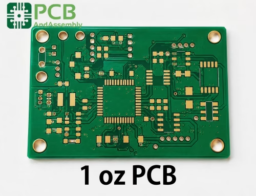
| 1 oz (standard) | 35 | 1.37 | 0.035 |
| 2 oz | 70 | 2.74 | 0.070 |
| 3 oz | 105 | 4.11 | 0.105 |
| 4 oz | 140 | 5.48 | 0.140 |
At 70 µm, 2 oz copper is roughly equivalent to the width of a human hair (50-70 µm). When you hold a 2 oz board, the traces are noticeably thicker than standard — you can see and feel the difference compared to a 1 oz board.
2 oz PCB Electrical Properties
The 70 µm thickness of 2 oz copper directly affects every electrical parameter of the board.
Current Carrying Capacity
Current capacity scales with copper cross-sectional area. Since 2 oz copper has twice the thickness of 1 oz, it carries approximately twice the current at the same trace width and temperature rise. This is the primary reason engineers specify 2 oz copper.
Current Capacity Table (External Layer, Various Temperature Rises):
| Trace Width | 10°C Rise | 20°C Rise | 30°C Rise |
| 10 mil | ~4.5A | ~6.5A | ~8.3A |
| 20 mil | ~9.5A | ~13.5A | ~17.0A |
| 50 mil | ~21.0A | ~30.0A | ~38.0A |
| 100 mil | ~42.0A | ~60.0A | ~76.0A |
| 200 mil | ~84.0A | ~120.0A | ~150.0A |
Note: Values are estimates based on IPC-2152. Internal layer capacity is approximately 50-70% of external due to reduced heat dissipation. Always verify with your specific design conditions and stackup.
For a practical comparison: a 10 mil trace on 1 oz carries ~2.3A (10°C rise), while the same trace on 2 oz carries ~4.5A — nearly double. This means you can either handle higher currents in the same board area or use narrower traces for the same current, freeing up routing space.
DC Resistance
Lower resistance is the mechanism behind the higher current capacity. At twice the copper thickness, DC resistance is halved:
| Trace Width | 2 oz Resistance (mΩ/inch) | 1 oz Resistance (mΩ/inch) |
| 10 mil | ~12 | ~24 |
| 20 mil | ~6 | ~12 |
| 50 mil | ~2.4 | ~4.8 |
| 100 mil | ~1.2 | ~2.4 |
This matters for more than just current capacity. Lower trace resistance means lower I²R losses, which means less heat generation, higher power efficiency, and smaller voltage drops across power distribution networks. For a 48V power rail carrying 10A, switching from 1 oz to 2 oz on the power plane cuts the voltage drop in half — from a potentially problematic 240 mV to 120 mV over a 10-inch trace.
Impedance Control
Thicker copper affects controlled-impedance designs. For a given target impedance (e.g., 50 Ω), a 2 oz trace must be significantly wider than a 1 oz trace because the increased conductor height reduces the characteristic impedance.
Approximate 50 Ω Microstrip Widths (2 oz on FR-4, Dk ~4.2):
| Dielectric Thickness | Trace Width (2 oz) | Trace Width (1 oz) |
| 8 mil (0.2 mm) | ~16 mil | ~15 mil |
| 12 mil (0.3 mm) | ~25 mil | ~23 mil |
| 20 mil (0.5 mm) | ~42 mil | ~38 mil |
The difference is approximately 8-12% wider than 1 oz for the same impedance target. This is manageable for most power-electronics designs with moderate routing density, but it can become a constraint in designs that combine high-current requirements with tight impedance budgets.
Thermal Performance
While copper’s thermal conductivity (~400 W/m·K) is the same regardless of thickness, the increased cross-sectional area of 2 oz copper improves thermal performance in two ways:
Heat Spreading: Thicker copper spreads heat away from hot components (MOSFETs, IGBTs, high-power LEDs) across a larger board area. This reduces peak junction temperatures and improves overall thermal management without additional heatsinks.
Reduced Self-Heating: Lower trace resistance means less I²R heating in the traces themselves. A trace that would run at a 30°C rise on 1 oz might only rise 15°C on 2 oz — or you can push the same current through a narrower trace with the same temperature rise.
Advantages and Disadvantages of 2 oz PCB
Advantages
Double the Current Capacity: The headline benefit — 2 oz copper handles roughly twice the current of 1 oz at the same trace width. A 50 mil trace that carries 11A on 1 oz copper carries approximately 21A on 2 oz (external, 10°C rise). This eliminates the need for excessively wide traces, parallel routing, or external bus bars in many power designs.
Superior Thermal Management: Thicker copper acts as a built-in heat sink. It spreads heat laterally from power components, reducing hot spots and improving overall thermal performance. For LED boards, this can mean the difference between a design that needs active cooling and one that works with passive convection alone.
Lower Voltage Drop: At double the cross-sectional area, voltage drop across power distribution traces is halved. For high-current, low-voltage designs (e.g., 3.3V or 5V power rails at 10A+), this is critical for maintaining regulation at the load.
Increased Mechanical Strength: Thicker copper provides greater rigidity and better resistance to trace lifting, pad cratering, and plated through-hole barrel cracking. In high-vibration environments (automotive, industrial machinery), 2 oz copper adds meaningful reliability margin.
Better Via Reliability: Plated through-holes on 2 oz copper layers carry more current and have greater mechanical integrity. The thicker copper in the via barrel can handle higher currents without excessive heating and is less susceptible to cracking under thermal cycling.
Disadvantages
Wider Minimum Trace Requirements: The etching process for 2 oz copper produces more lateral undercut than 1 oz. Standard minimum trace/space rules increase from 4-5 mils (1 oz) to 6-8 mils (2 oz). For high-density digital sections of a mixed-signal board, this can be a limitation.
Higher Cost: 2 oz boards typically cost 20-50% more than equivalent 1 oz boards. The premium comes from higher material cost, longer etching time, and more process control required. For high-volume consumer products, this premium can be significant.
Impedance Constraints: As noted above, 2 oz traces must be wider to achieve the same characteristic impedance. This can complicate designs that need both high-current handling and controlled-impedance transmission lines, such as RF power amplifiers.
Lamination Challenges: In multilayer boards, 2 oz copper requires thicker prepreg and modified lamination parameters (higher pressure, adjusted flow). Uneven copper distribution can cause warpage, so careful stackup balancing is essential.
| Parameter | 1 oz | 2 oz | Best For |
| Min trace width | 4-5 mils | 6-8 mils | 1 oz |
| Current capacity | Standard | 2× Standard | 2 oz |
| Thermal spreading | Good | Excellent | 2 oz |
| DC resistance | Standard | 50% lower | 2 oz |
| Mechanical strength | Good | Excellent | 2 oz |
| Impedance control width | Narrower | Wider | 1 oz |
| Cost | Baseline | +20-50% | 1 oz |
| Quick-turn availability | Yes | Most fabs | 1 oz |
Applications for 2 oz PCB
2 oz copper is the go-to choice whenever standard 1 oz cannot handle the current, thermal, or mechanical demands of the design.
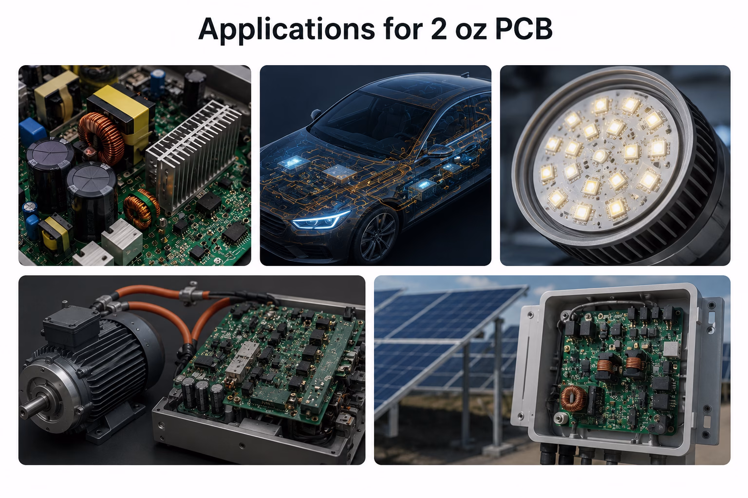
Power Electronics
Power supplies, DC-DC converters, and voltage regulator modules are the most common applications for 2 oz copper. The combination of high current, the need for low voltage drop, and thermal management requirements makes 2 oz the natural choice.
- Switch-mode power supply (SMPS) output stages
- DC-DC converter modules (buck, boost, buck-boost)
- Point-of-load (POL) regulator boards
- AC-DC adapter and charger PCBs
- Uninterruptible power supply (UPS) control boards
In a typical 48V-to-12V buck converter handling 20A at the output, 2 oz copper on the power plane keeps I²R losses manageable and maintains regulation at the load. On 1 oz, the same design would need either a thicker bus bar, additional copper layers, or wider traces that consume board area.
Automotive Electronics
Automotive environments combine high current, wide temperature ranges, and severe vibration — all of which favor 2 oz copper.
- Electric vehicle (EV) battery management systems (BMS)
- Motor controllers for power steering, windows, and seats
- LED headlight and taillight driver modules
- On-board charger (OBC) control boards
- DC-DC converter modules for vehicle power distribution
- Engine control unit (ECU) power supply sections
Automotive PCBs must pass rigorous thermal cycling tests (typically -40°C to +125°C or higher). The thicker copper in 2 oz boards provides additional margin against solder joint fatigue and plated through-hole cracking during these extreme temperature swings.
LED Lighting
High-power LED arrays generate significant heat that must be conducted away from the LED junction to keep temperatures within safe limits. 2 oz copper PCBs are widely used in LED applications for this reason.
- High-power LED grow lights for horticulture
- Stadium and arena lighting fixtures
- Street and parking lot luminaires
- Automotive LED headlight assemblies
- UV curing LED arrays
- Medical and surgical lighting
For LED designs, 2 oz copper on an aluminum-backed or metal-core PCB (MCPCB) provides an excellent thermal path from LED junction to heatsink. The copper spreads heat laterally before it reaches the dielectric and aluminum base, reducing the effective thermal resistance of the stack.
Motor Drives and Inverters
Motor controllers and inverters switch substantial currents through MOSFETs or IGBTs at frequencies from a few kHz to tens of kHz. 2 oz copper minimizes switching losses in the PCB traces and helps manage the thermal load from power semiconductors.
- Industrial servo motor drives
- HVAC compressor inverters
- Electric bicycle and scooter motor controllers
- Robotics joint motor drivers
- Drone and UAV motor controllers
- Pump and fan variable-frequency drives
The combination of high peak currents (often 30-100A+ in short pulses) and the need for low-inductance power loops makes 2 oz copper the practical minimum for most motor drive designs above ~100W.
Solar and Industrial Applications
Solar inverters and charge controllers handle sustained DC currents at moderate voltages, while industrial environments demand reliability under harsh conditions. 2 oz copper addresses both requirements with low-resistance power paths and added mechanical robustness.
- Solar microinverters, MPPT charge controllers, and grid-tie inverter power stages
- PLC power supply and output driver boards
- Motor starter and contactor control boards
- Power monitoring, metering, and process control modules
| Industry | Typical Max Current | Key Requirements |
| Power electronics | 10-100A | Low voltage drop, thermal management |
| Automotive | 5-50A | Thermal cycling, vibration, reliability |
| LED lighting | 1-10A | Heat spreading, compact form factor |
| Motor drives | 10-100A+ (pulsed) | Low inductance, high peak current |
| Solar & Industrial | 5-60A | Efficiency, robustness, surge tolerance |
2 oz vs 1 oz vs 3 oz: How to Choose the Right Copper Weight
The decision to use 2 oz copper should be driven by specific electrical, thermal, or mechanical requirements — not by default. If 1 oz works, it will be cheaper and faster. If 1 oz doesn’t work, 2 oz is almost always the next logical step.
Decision Framework
| Design Requirement | Recommended Weight | Reason |
| Current > 3A per trace (sustained) | 2 oz | 1 oz requires very wide traces |
| Multiple high-current traces | 2 oz | Saves total board area |
| High-power LED thermal management | 2 oz | Better heat spreading without heatsink |
| Automotive/high-vibration | 2 oz | Added mechanical margin |
| High-reliability (IPC Class 3) | 2 oz | Better via and pad reliability |
| Current > 15A per trace | 3 oz+ | Beyond practical 2 oz trace widths |
| Extreme thermal cycling | 3 oz+ | Maximum via barrel reliability |
| Cost-sensitive high-volume | 1 oz | Lowest cost, fastest turnaround |
| Fine-pitch digital routing | 1 oz (mixed) | 1 oz on signal layers, 2 oz on power |
Practical Hybrid Approaches
Many production designs mix copper weights to optimize cost, density, and performance. The most common pattern uses 2 oz on power layers and 1 oz (or even 0.5 oz) on signal layers.
Example 4-Layer Power Design Stackup:
| Layer | Function | Copper Weight | Reason |
| L1 (Top) | Power components + high-current traces | 2 oz | Component pads, high-current routing |
| L2 | Ground plane | 2 oz | Low-impedance ground return, thermal spreading |
| L3 | Power plane | 2 oz | Low-resistance power distribution |
| L4 (Bottom) | Signal + low-power components | 1 oz | Standard digital/analog routing |
Example 6-Layer Mixed Design Stackup:
| Layer | Function | Copper Weight | Reason |
| L1 (Top) | Power components + high-current | 2 oz | High-current pads and traces |
| L2 | Ground plane | 1 oz | Standard reference plane |
| L3 | Signal (digital) | 0.5 oz | Fine-line digital routing |
| L4 | Signal (analog) | 0.5 oz | Clean analog routing |
| L5 | Power plane | 2 oz | High-current distribution |
| L6 (Bottom) | Power components | 2 oz | High-current return paths |
The key to successful mixed-weight stackups is copper balancing: mirrored layers should have matching copper weights to prevent warpage. If L1 is 2 oz, L6 should also be 2 oz. If L2 is 1 oz, L5 should be 1 oz.
Need PCB Manufacturing or Assembly?
Get a free quote within 24 hours. We specialize in prototype-to-production PCB/PCBA for hardware teams worldwide.
Cost Analysis: 2 oz vs 1 oz
The cost premium for 2 oz copper comes from multiple factors, but for most designs it’s a manageable increase — typically 20-50% over equivalent 1 oz boards.
| Cost Factor | 2 oz Impact | Why |
| Raw material | Higher (+20-30%) | 2× the copper per layer, fewer laminate suppliers |
| Etching | Higher (+15-25%) | Longer etch time, more process control, lower throughput |
| Drilling | Slightly higher | Adjusted parameters, more frequent drill changes |
| Lamination | Slightly higher | Modified prepreg and cycle parameters |
| Yield | Comparable | Better mechanical robustness offsets etching challenges |
| Lead time | +2-5 days typical | Requires scheduling on compatible production lines |
Bottom line: If your design requires 2 oz copper for electrical or thermal reasons, the 20-50% cost premium is usually far cheaper than the alternatives: wider traces requiring larger boards, additional copper layers, external bus bars, or active cooling solutions. In many designs, 2 oz copper actually reduces total BOM cost by eliminating heatsinks or enabling a simpler board form factor.
For cost-sensitive high-volume production, a mixed-weight approach — 2 oz on power layers, 1 oz elsewhere — captures most of the benefits at a lower premium.
2 oz Copper Foil Types
The type of copper foil used for 2 oz layers affects performance and manufacturability.
| Foil Type | Description | Surface Roughness | Best For |
| ED (Electro-Deposited) | Standard foil, most cost-effective | Standard (~5-8 µm) | Most power electronics applications |
| HTE (High-Temperature Elongation) | Improved thermal cycling durability | Standard (~5-8 µm) | Automotive, high-reliability |
| RTF (Reverse Treated Foil) | Smooth on circuit side | Low (~3-4 µm) | Mixed-signal with impedance control |
| RA (Rolled Annealed) | Smoothest, most ductile | Lowest (< 1 µm) | Flex and rigid-flex with 2 oz |
For most 2 oz power designs, standard ED copper is perfectly adequate and most cost-effective. HTE foil is recommended for automotive and other high-reliability applications where thermal cycling resistance matters. RTF and RA foils are rarely used for 2 oz because the thickness limits the fine-line benefits these smooth foils provide.
Frequently Asked Questions About 2 oz PCB
What is 2 oz copper thickness in mm?
2 oz copper has a nominal thickness of 0.070 mm (70 µm, or 2.74 mils). This is the base copper thickness before processing. On outer layers, finished thickness is typically higher (80-90 µm) due to additional plating during via formation and surface finishing. Inner layers remain close to the base 70 µm.
How much current can a 2 oz PCB trace carry?
A 10 mil wide trace on 2 oz copper (external layer) can carry approximately 4.5A with a 10°C temperature rise, 6.5A with 20°C, or 8.3A with 30°C, based on IPC-2152. This is roughly double the capacity of the same trace on 1 oz copper. For accurate values, use an IPC-2152 compliant calculator with your specific design conditions.
What’s the minimum trace width for 2 oz copper?
Standard manufacturing capability for 2 oz copper is 8 mil (0.2 mm) trace width and spacing. Advanced fabricators with tight process control can achieve 6 mil (0.15 mm) trace/space. Going below 6 mil on 2 oz copper significantly increases the risk of opens, shorts, and uneven etching — if your design requires finer traces, route those signals on 1 oz or 0.5 oz layers in a mixed-weight stackup.
Is 2 oz copper considered heavy copper?
In the PCB industry, “heavy copper” typically refers to 3 oz and above. 2 oz occupies a middle ground — it provides significant current-handling benefits over standard 1 oz, but it doesn’t require the specialized heavy-copper manufacturing lines that 4 oz+ designs need. Most fabricators process 2 oz on their standard production lines with adjusted parameters.
How does 2 oz compare to 1 oz for cost?
2 oz boards typically cost 20-50% more than equivalent 1 oz boards, depending on the number of layers, board size, and production volume. The premium comes from higher copper material cost, longer etching time, and modified process parameters. For prototype quantities, the premium is on the lower end (20-30%); for high-volume production, it’s typically 25-40%.
Can 2 oz and 1 oz copper be used in the same board?
Yes — mixed-weight stackups are common in power electronics designs. A typical configuration uses 2 oz on outer layers for high-current component connection and power planes, with 1 oz or 0.5 oz on inner signal layers for digital and analog routing. The fabricator handles the different copper foils during lamination, but careful stackup design is required to ensure copper balance and prevent warpage.
When should I choose 2 oz over 1 oz for my design?
Choose 2 oz when your design meets any of these conditions: sustained trace currents above 3A, multiple high-current traces competing for board space, thermal management concerns around power components, high-vibration operating environment, or reliability requirements that benefit from thicker copper (IPC Class 3, automotive). If none of these apply, 1 oz is almost always the better choice for cost, turnaround time, and design simplicity.
Does 2 oz copper affect solder joint reliability?
2 oz copper generally improves solder joint reliability. The thicker copper provides more thermal mass at the pad, which can require slightly adjusted reflow profiles (longer soak time, marginally higher peak temperature). However, once properly soldered, 2 oz pads and plated through-holes have greater mechanical integrity and better resistance to thermal cycling fatigue than 1 oz.
Conclusion
The 2 oz PCB is the practical upgrade from standard copper weight — providing roughly double the current capacity, significantly better thermal management, and improved mechanical reliability at a manageable cost premium. For power electronics, automotive systems, LED lighting, motor drives, and solar inverters, 2 oz copper solves problems that 1 oz simply cannot address without workarounds.

Get Quote Free