What is Solder Paste? Complete Guide to Composition, Types, and SMT Printing
Solder paste is a material that consists of very fine metal powder with flux. It is used to firmly attach electronic components to the PCB pads, ensuring both conductivity and stability. Unlike traditional solder wires, solder paste is semi-solid and much more convenient for precise application on the circuit board, making it suitable for those complex-structured or densely packed PCBs.
Get Your PCB Quote!
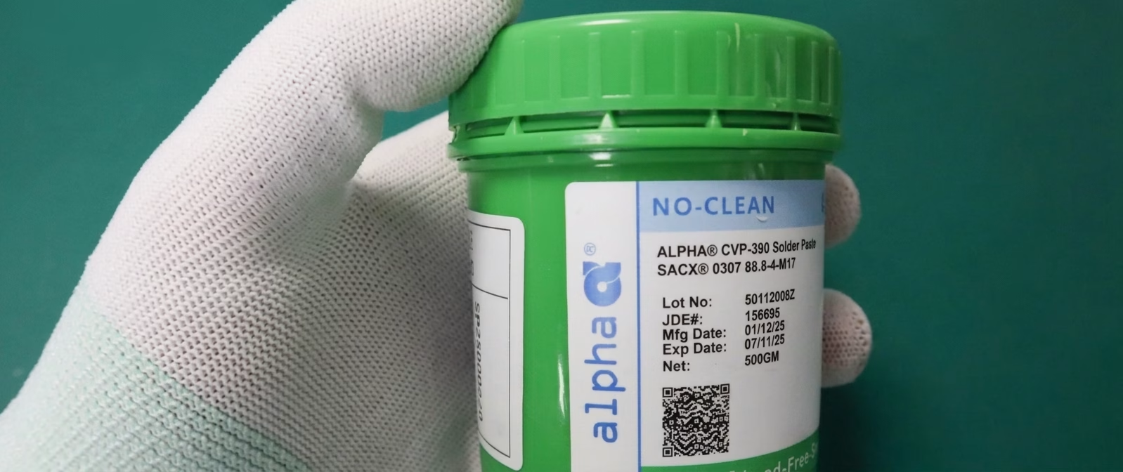
Table of Contents
If you’ve ever watched a pick-and-place machine at work, you’ve seen the magic of SMT assembly — tiny components flying into position at impossible speeds. But the unsung hero of that process isn’t the machine. It’s the paste sitting under every component: solder paste.
Solder paste is the material that makes modern PCB assembly possible. Without it, those 0402 resistors, fine-pitch BGAs, and QFN packages wouldn’t stay in place long enough to reach the reflow oven.
What Is Solder Paste?
Solder paste is a thixotropic mixture of metal solder powder suspended in a flux vehicle. It’s the adhesive that holds surface-mount components in place during placement and the material that forms permanent electrical and mechanical solder joints during reflow.
Think of it as the glue that becomes the weld — a temporary binder during assembly that transforms into a reliable metallic connection after heating.
Composition Breakdown
Solder paste has two main components, each with a specific job:
| Component | Typical Content | Function |
| Solder Powder | 88–92% by weight (50–60% by volume) | Forms the metallic joint after reflow |
| Flux Vehicle | 8–12% by weight (40–50% by volume) | Removes oxides, prevents re-oxidation, enables wetting, controls rheology |
The powder-to-flux ratio determines how the paste behaves during printing and reflow. Too much powder and the paste becomes stiff and doesn’t release from the stencil. Too much flux and the paste slumps, causing bridging between adjacent pads.
Solder Paste Types by Alloy
The solder powder itself comes in different alloy compositions, each with distinct melting points, mechanical properties, and regulatory compliance.
Leaded vs. Lead-Free Solder Paste
| Property | Sn63Pb37 (Leaded) | SAC305 (Lead-Free) | SAC387 (Lead-Free) |
| Composition | 63% Sn, 37% Pb | 96.5% Sn, 3.0% Ag, 0.5% Cu | 96.0% Sn, 3.8% Ag, 0.2% Cu |
| Melting Point | 183°C (eutectic) | 217–220°C | 217–221°C |
| Peak Reflow Temp | 210–220°C | 245–260°C | 245–260°C |
| Wetting | Excellent | Good | Good |
| Reliability | Very good — proven for decades | Good — more brittle than leaded | Good — slightly stronger than SAC305 |
| RoHS Compliant | No | Yes | Yes |
| Relative Cost | ~1x (baseline) | ~1.5–2x | ~2x |
Sn63Pb37 has been the industry standard for over 40 years. Its eutectic composition means it transitions directly from solid to liquid without a plastic phase, which simplifies the reflow process. The lead content improves ductility, making joints more resistant to thermal cycling fatigue.
SAC305 is the most common lead-free alternative, driven by the RoHS (Restriction of Hazardous Substances) directive. It requires a higher reflow temperature, which means more thermal stress on components and boards. However, it’s RoHS-compliant and widely accepted across consumer, industrial, and automotive electronics.
SAC387 offers slightly higher silver content for improved mechanical strength, but the difference is marginal for most applications. SAC305 remains the dominant choice.
Other Notable Alloys
- Sn42/Bi58(Tin-Bismuth, Lead-Free): Melts at 138°C — useful for temperature-sensitive components. More brittle than SAC305 but can be a good choice for step-soldering applications.
- 5/Ag3.5(Tin-Silver, Lead-Free): Melts at 221°C. Higher cost than SAC305 with similar performance.
- In48/Sn52(Indium-Tin): Melts at 118°C — used for specialized cryogenic or temperature-sensitive assemblies.
Solder Powder Particle Sizes
Particle size is classified by the IPC J-STD-005 standard. Smaller particles enable finer-pitch printing but have higher surface area, making them more prone to oxidation.
| Type | Particle Size (µm) | Best For | Minimum Pitch |
| Type 3 | 25–45 | General SMT assembly | 0.65 mm+ |
| Type 4 | 20–38 | Fine-pitch SMT | 0.4 mm |
| Type 5 | 10–25 | Ultra-fine pitch, micro-BGAs | 0.3 mm |
| Type 6 | 5–15 | Advanced packaging, 0.3 mm BGAs | < 0.3 mm |
Type 3 is the workhorse for standard assembly. If you’re assembling boards with 0805, 0603, or larger components and standard-pitch QFPs, this is what you need.
Type 4 handles most fine-pitch work — anything down to 0.4 mm pitch. It’s the second most common choice in production.
Type 5 and Type 6 are for advanced miniaturization. The smaller particles print cleaner on tiny apertures but cost more and have shorter stencil life due to faster flux drying.
Flux Categories
The flux vehicle is just as important as the powder. It determines how well the paste prints, how it behaves during reflow, and whether you need to clean the board afterward.
| Flux Type | Activity Level | Residue | Requires Cleaning | Typical Use |
| R (Rosin) | Low | Clear, non-corrosive | No | High-reliability, low-activity applications |
| RMA (Rosin Mildly Activated) | Moderate | Clear, non-conductive | Optional | General electronics, most common type |
| RA (Rosin Activated) | High | Dark, potentially corrosive | Yes | Difficult-to-solder surfaces |
| No-Clean | Moderate | Clear, benign | No | Mass production, consumer electronics |
| Water-Soluble | High | Clear, water-rinsable | Yes (critical!) | High-reliability, medical, mil/aero |
No-Clean flux is the dominant choice in modern SMT assembly. It leaves a transparent, non-conductive, non-corrosive residue that doesn’t need to be removed. This saves a cleaning step and reduces cost.
Water-Soluble flux offers the best wetting performance but requires thorough cleaning with deionized water. Residual activators left on the board can cause corrosion and field failures.
RMA strikes a good balance for prototype and mid-volume work. It offers reliable soldering with residues that are generally safe to leave on the board.
Storage and Handling
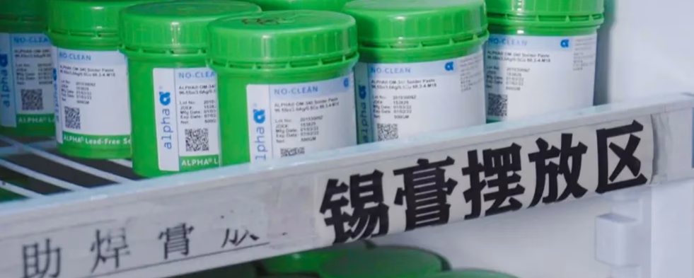
Solder paste is a perishable material. Mishandling it is one of the most common causes of SMT defects.
Storage Requirements
| Parameter | Requirement |
| Storage Temperature | 0–10°C (32–50°F), refrigeration required |
| Shelf Life (Refrigerated) | 6–12 months (check manufacturer date code) |
| Shelf Life (Room Temp, Unopened) | 2–4 weeks |
| Opened Jar Life (at Printer) | 8–24 hours (varies by type — Type 5/6 dries faster) |
Need PCB Manufacturing or Assembly?
Get a free quote within 24 hours. We specialize in prototype-to-production PCB/PCBA for hardware teams worldwide.
The SMT Printing Process
Solder paste application is the first and most critical step in the SMT assembly process. Get this wrong, and nothing downstream can fully fix it.
Step 1: Stencil Printing
The stainless steel stencil sits aligned over the bare PCB. A squeegee blade pushes solder paste across the stencil, forcing it into the apertures. When the stencil lifts, the paste deposits remain on the pads.
Key parameters:
| Parameter | Typical Range | Effect |
| Squeegee Pressure | 5–15 kg | Too low = insufficient paste; too high = smearing |
| Print Speed | 25–100 mm/s | Slower = better paste release but lower throughput |
| Separation Speed | 1–10 mm/s | Slower separation = cleaner paste release for fine pitch |
| Stencil Thickness | 0.1–0.2 mm (4–8 mil) | Thicker = more paste; thinner = better fine-pitch resolution |
Step 2: Pick-and-Place
Components are placed into the wet solder paste. The paste’s tackiness holds them in place. This is where paste rheology matters — the paste must be tacky enough to hold components during board movement but not so sticky that it pulls off during placement.
Step 3: Reflow Soldering
The board passes through a controlled heating profile that activates the flux, melts the powder, and forms the solder joint.
Typical Reflow Profile Zones
| Zone | Temperature Range | Duration | Purpose |
| Preheat | 25–150°C | 60–120 sec | Gradually heat board and components |
| Soak | 150–200°C | 60–120 sec | Activate flux, equalize temperature across board |
| Reflow (Spike) | 217–260°C | 30–90 sec above liquidus | Melt solder powder, form intermetallic bonds |
| Cooling | 260°C → below 100°C | 30–60 sec | Solidify joints, control microstructure |
For SAC305, the peak temperature should reach 245–260°C, with time above liquidus (217°C) kept between 30 and 90 seconds. Too short and the joint doesn’t form properly. Too long and you risk intermetallic growth that weakens the joint.
Common Solder Paste Defects
Even with good paste, defects happen. Here are the most common ones and their root causes.
| Defect | What It Looks Like | Root Causes | Prevention |
| Tombstoning | Component stands on one end | Uneven wetting, pad size mismatch, uneven heating | Balance pad sizes, optimize reflow profile |
| Bridging | Solder connects adjacent pads | Too much paste, misalignment, paste slump | Reduce stencil thickness, check alignment |
| Solder Balls | Tiny spheres around joints | Moisture in paste, oxidation, flux spattering | Proper thawing, fresh paste, correct profile |
| Head-in-Pillow | Component lead sits on but doesn’t merge into solder | BGA oxidation, poor reflow profile, warpage | Use flux-cored balls, optimize soak zone |
| Insufficient Solder | Joint looks starved, incomplete | Insufficient paste volume, aperture clogging | Check stencil aperture ratio, clean stencil regularly |
| Solder Beading | Large isolated solder balls near chip components | Outgassing of trapped flux under components | Reduce paste volume under components, improve profile |
For a deeper look at assembly defects and how to solve them, check out our guide on common PCB assembly defects.
How to Choose the Right Solder Paste
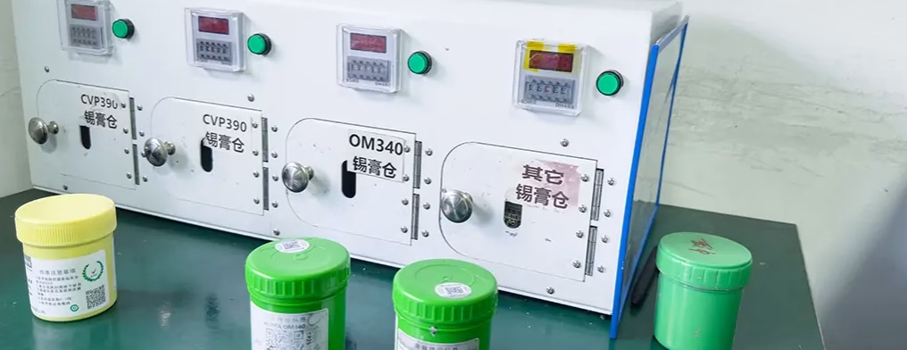
Selecting the right paste depends on your assembly requirements. Here’s a practical decision framework.
Step 1: Decide Leaded vs. Lead-Free
- Consumer/commercial products: Use SAC305 (RoHS-compliant, widely available)
- Medical/mil/aero (exempt from RoHS): Sn63Pb37 for proven reliability and easier processing
- Temperature-sensitive assemblies: Consider Sn42/Bi58 (low melt) for step-soldering
Step 2: Choose Particle Size
- Standard components (0603+, QFP ≥ 0.65mm pitch): Type 3
- Fine-pitch (QFP 0.4–0.5mm pitch): Type 4
- Micro-BGA, 0.3mm pitch: Type 5
- Advanced packaging, CSP: Type 6
Step 3: Select Flux Type
- Mass production: No-Clean (fastest, lowest cost)
- High-reliability / medical / aero: Water-Soluble (best wetting, must clean)
- Prototype / short runs: RMA (forgiving, versatile)
Step 4: Verify Stencil Compatibility
Your stencil design must match the paste type. The key metric is area ratio:
Area Ratio = Aperture Opening Area ÷ Aperture Wall Area
- Target: > 0.66 for standard Type 3/4 pastes
- Target: > 0.50 for Type 5/6 pastes (with optimized printing parameters)
If your area ratio drops below these thresholds, the paste won’t release cleanly from the stencil, causing insufficient solder defects.
For detailed stencil design guidelines, check our article on SMT stencils, types, and design guidelines.
Useful Resources
Industry Standards: – IPC J-STD-005: Requirements for Solder Paste — the primary paste specification – IPC J-STD-001: Requirements for Soldered Electrical and Electronic Assemblies – IPC-7525: Stencil Design Guidelines — essential for proper aperture design
Design Tools: – Solder paste calculator (aperture area ratio, aspect ratio) – Reflow profile optimization software (KIC, SolderStar)
Related Articles: – PCB Assembly Process: Complete Step-by-Step Guide — how solder paste fits into the full assembly flow – SMT vs. Through-Hole Components: Engineering Guide — when SMT (and solder paste) applies vs. through-hole – Wave Soldering vs Reflow Soldering: Processes, Differences & When to Use Each — reflow vs wave soldering explained
Frequently Asked Questions
What is solder paste made of?
Solder paste is a mixture of 88–92% metal solder powder (by weight) and 8–12% flux vehicle. The solder powder is typically a tin-lead or tin-silver-copper alloy, and the flux contains activators, solvents, and rheology modifiers that enable printing and promote wetting during reflow.
Can solder paste be used for hand soldering?
Solder paste is designed for stencil printing and reflow soldering, not hand soldering. For hand assembly, use traditional wire solder with separate liquid flux. You can use solder paste for rework on individual components using a hot air station, but it’s not practical for manual through-hole soldering.
How long does solder paste last after opening?
Once opened, solder paste has a limited working life. At typical factory conditions (22–25°C, 40–60% RH), opened paste lasts 8–24 hours on the stencil. Type 5 and Type 6 pastes have shorter stencil lives than Type 3 due to faster solvent evaporation. Always follow the manufacturer’s specification for open-jar life.
What is the difference between Type 3 and Type 4 solder paste?
Type 3 paste has larger particles (25–45 µm) and is suitable for standard SMT assembly with component pitches of 0.65 mm or larger. Type 4 has finer particles (20–38 µm) and is designed for fine-pitch components down to 0.4 mm. Type 4 paste prints better on small stencil apertures but has a shorter stencil life because the finer particles expose more surface area to oxidation and solvent evaporation.
Why does solder paste need to be refrigerated?
Refrigeration slows the chemical reaction between the flux activators and the solder powder. Without refrigeration, the flux degrades, the paste’s rheology changes, and soldering performance deteriorates. Refrigerated paste typically lasts 6–12 months. Paste stored at room temperature may degrade in weeks.
What causes solder balls after reflow?
Solder balls are typically caused by moisture in the paste condensing into steam during reflow, which ejects small droplets of molten solder. Other causes include oxidized powder, excessive flux spattering, incorrect reflow profile (too rapid heating), or paste that wasn’t properly thawed before use.
What is SPI in PCB assembly?
SPI (Solder Paste Inspection) is an automated 3D inspection step performed immediately after solder paste printing and before component placement. SPI systems use laser or structured light to measure the volume, height, area, and alignment of paste deposits on every pad. It catches insufficient paste, excess paste, bridging, and misalignment — before components are placed and reflowed, when defects are still fixable.
What is the difference between No-Clean and Water-Soluble solder paste?
No-Clean paste leaves a transparent, non-conductive residue that can remain on the board without causing reliability issues — no cleaning step is needed. Water-Soluble paste offers better wetting and leaves residues that must be thoroughly cleaned with deionized water. If the cleaning step is missed, water-soluble residues can absorb moisture and cause corrosion, leading to field failures.
Conclusion
Solder paste is the foundation of SMT assembly — the material that bridges bare PCBs and functional electronic products. Getting it right means understanding four variables: alloy composition, particle size, flux type, and handling procedure.
For standard production, SAC305 Type 4 with No-Clean flux covers the majority of applications. For high-reliability work, consider Sn63Pb37 (if RoHS-exempt) or Water-Soluble flux with a thorough cleaning process. Always verify your stencil design provides adequate area ratio for the paste you’re using, and never compromise on storage and thawing procedures.
The best assembly results come from controlling the printing process — SPI verification, proper stencil maintenance, and consistent reflow profiling. When you treat solder paste with the same engineering rigor you apply to your PCB design, the defects that plague most assembly runs simply don’t appear.

Get Quote Free