Rogers RO4350B PCB Materials: Specs , Usage Considerations & Applications guide
Rogers RO4350B material is a high-frequency laminate developed for applications in the approximate range of 8–40 GHz. A guide to Rogers RO4350B material specs, copper roughness, and lamination.
Get Your PCB Quote!
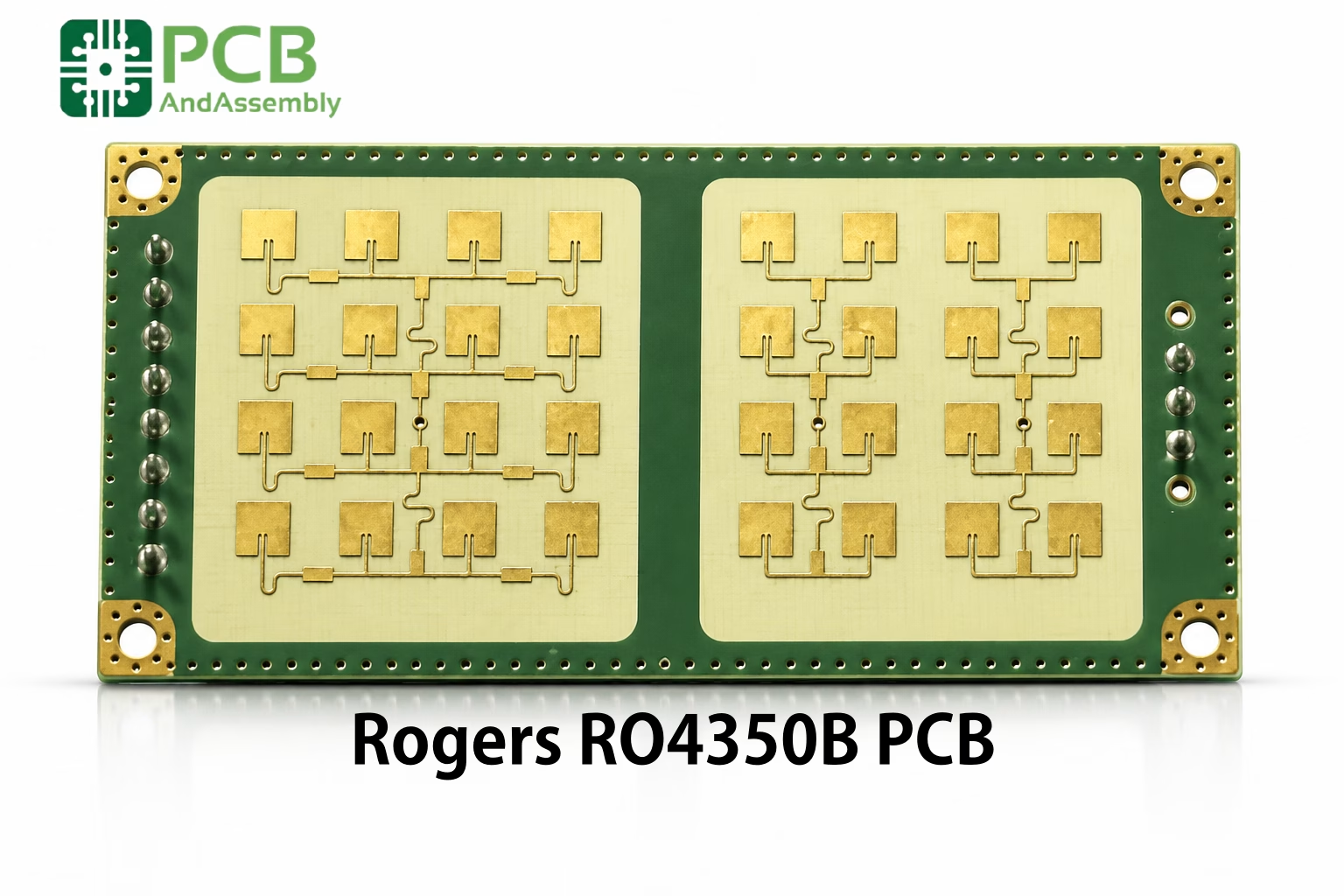
Table of Contents
Standard FR-4 material is completely unsuitable for operation in the microwave band. After 15 years of specifying laminates for high-frequency systems, I have found that Rogers RO4350B is the most forgiving, cost-effective material for designs operating between 500 MHz and 30 GHz—provided you know how to navigate its fabrication quirks.
Far too many designers treat RO4350B as a drop-in FR-4 replacement simply because the datasheet says “FR-4 process compatible.” While the processing steps are similar, the material physics are radically different. This guide exposes the critical parameters, copper profile traps, and stack-up realities that determine whether your high-frequency board succeeds in production or ends up in the scrap bin.
What Is RO4350B PCB Material?
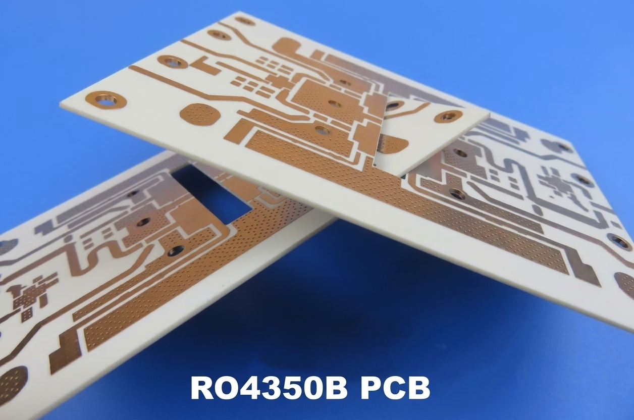
RO4350B is a patented hydrocarbon/ceramic laminate developed by Rogers Corporation for RF, microwave, and high-speed digital applications. Unlike standard FR-4, which uses epoxy resin reinforced with woven glass, RO4350B combines three key elements:
- Hydrocarbon thermoset resin: Hydrocarbon thermoset resin Maintains stable dielectric properties where epoxy-based materials drift. Because it is thermoset rather than thermoplastic (like PTFE), the cured board behaves like FR-4 during mechanical drilling and lamination—no sodium naphthalene etching, no special via treatments.
- Ceramic filler: Ceramic filler Particles distributed throughout the resin yield high thermal conductivity (0.69 W/m·K) and restrict dimensional movement under thermal loads. They also make the laminate highly abrasive to fabrication tooling—a factor that directly affects drill life and via reliability.
- Woven glass reinforcement: Woven glass reinforcement E-glass fabric provides mechanical strength. The glass transition temperature exceeds 280°C, enabling full lead-free solder compatibility.
This formulation delivers electrical characteristics approaching PTFE-based materials at a fraction of the processing complexity and cost.
Need PCB Manufacturing or Assembly?
Get a free quote within 24 hours. We specialize in prototype-to-production PCB/PCBA for hardware teams worldwide.
Key RO4350B Specifications
Electrical Properties
| Parameter | Value | Test Condition |
| Dielectric Constant (Dk) | 3.48 ± 0.05 | 10 GHz, IPC-TM-650 |
| Dissipation Factor (Df) | 0.0037 | 10 GHz |
| Volume Resistivity | 1.7 × 10¹⁰ MΩ·cm | Condition A |
| Surface Resistivity | 4.2 × 10⁹ MΩ | Condition A |
| Electrical Strength | 31.2 kV/mm | IPC-TM-650 |
Thermal Properties
| Parameter | Value | Notes |
| Glass Transition Temperature (Tg) | > 280°C | DSC |
| CTE (X, Y axis) | 10–12 ppm/°C | TMA |
| CTE (Z axis) | 32 ppm/°C | Below Tg |
| Thermal Conductivity | 0.69 W/m·K | 80°C |
| Decomposition Temp (Td) | 390°C | TGA (5% weight loss) |
Available Thicknesses
RO4350B is available in multiple standard thicknesses to accommodate different impedance targets and power-handling requirements:
| Thickness (in) | Thickness (mm) | Common Applications |
| 0.004″ | 0.101 mm | Thin microstrip, tight coupling |
| 0.010″ | 0.254 mm | General RF applications |
| 0.020″ | 0.508 mm | Standard microwave boards (most common) |
| 0.030″ | 0.762 mm | Power handling applications |
| 0.060″ | 1.524 mm | Thick substrates, structural needs |
Electrical Performance: Where FR-4 Hits the Frequency Wall
Standard FR-4 is a fantastic material for low-frequency digital and power circuits, but it degrades rapidly above 2 GHz. Its primary limitation is the dissipation factor (Df). High-Tg FR-4 typically exhibits a Df of 0.015 to 0.020. At 10 GHz, this level of dielectric loss attenuates signals so severely that receiver sensitivity drops and transmitter efficiency is lost to heat.
RO4350B has a nominal Df of 0.0037 at 10 GHz—approximately 4–5× lower than FR-4. Additionally, FR-4 suffers from significant dielectric constant drift across temperature and frequency. Its Dk can vary from 4.2 to 4.7 depending on resin-to-glass ratios and operating frequency, destroying tight impedance targets. RO4350B maintains a tight Dk of 3.48 ± 0.05 from low frequencies through 40 GHz.
The Copper Roughness Trap: Why Your Design Dk Is Wrong
One of the most common design failures I see occurs when engineers use the datasheet Dk of 3.48 blindly in their impedance calculators. They receive fabricated boards, test them on a Vector Network Analyzer (VNA), and find that the phase velocity is slower than expected and the impedance is lower than the calculated 50Ω.
The cause is copper surface roughness at the substrate-to-foil interface. At 10 GHz, the skin depth of copper is approximately 0.66 μm. If the surface roughness profile (Rq or Rz) is comparable to the skin depth, current must travel up and down the copper hills and valleys, increasing the effective inductance per unit length, slowing propagation velocity, and raising the effective “design Dk.”
Rogers specifies a design Dk of 3.66 for standard microstrip calculations—not 3.48. Using the raw datasheet value will produce traces that are too narrow and miss impedance targets.
| Copper Foil Type | Avg Roughness (Rq) | Nominal Dk @10 GHz | Actual Design Dk (20 mil core) | RF Loss Impact |
| Standard ED (Electrodeposited) | 2.1 μm | 3.48 | 3.66 – 3.70 | High loss; substantial phase distortion |
| Low-Profile (Lopro) | 1.2 μm | 3.48 | 3.56 – 3.60 | Moderate loss; balanced cost/performance |
| Reversed Treated Foil (RTF) | 1.5 μm | 3.48 | 3.60 – 3.64 | Optimized for mechanical peel strength |
| Rolled / VLP (Very Low Profile) | 0.5 μm | 3.48 | 3.50 – 3.52 | Lowest loss; ideal for millimeter-wave |
I have seen designs where a 20-mil RO4350B core with standard electrodeposited copper exhibited an actual design Dk of 3.68. Always consult your fabricator to confirm the exact copper option they stock, and use the design Dk—not the process Dk—when calculating line widths.
Why Z-Axis CTE Matters for Multilayer Reliability
In multilayer designs, the coefficient of thermal expansion (CTE) in the Z-axis is a critical reliability factor. Copper has a CTE of ~17 ppm/°C. Standard FR-4 has a Z-axis CTE of 60–70 ppm/°C below its glass transition temperature, ballooning to over 250 ppm/°C above Tg during lead-free reflow (peak 260°C). This aggressive expansion exerts tensile stress on plated through-hole barrels and microvias, causing barrel cracking, corner cracking, or inner-layer pad separation.
RO4350B addresses this with a Z-axis CTE of only 32 ppm/°C across −55°C to +288°C—roughly half that of FR-4. Combined with its Tg > 280°C and decomposition temperature of 390°C, it resists the thermal degradation common in lead-free assembly and ensures via reliability through thermal cycling.
Choosing Between RO4350B, RO4003C, and High-Tg FR-4
Engineers often specify RO4003C because of its slightly lower dissipation factor (0.0027 vs. 0.0037 at 10 GHz). This is a classic over-specification trap. RO4003C does not contain bromine and lacks a UL 94 V-0 flame rating. If your product requires UL certification—which applies to virtually all commercial telecom, industrial radar, and 5G infrastructure hardware—you must use RO4350B. The electrical performance difference is negligible for these applications.
| Parameter | RO4350B | RO4003C | High-Tg FR-4 (Isola 370HR) | Unit / Condition |
| Dielectric Constant (Dk) | 3.48 ± 0.05 | 3.38 ± 0.05 | 4.17 | At 10 GHz |
| Dissipation Factor (Df) | 0.0037 | 0.0027 | 0.0160 | At 10 GHz |
| Thermal Conductivity | 0.69 | 0.71 | 0.40 | W/m·K |
| Z-Axis CTE | 32 | 46 | 45 | ppm/°C (below Tg) |
| Glass Transition (Tg) | > 280 | > 280 | 180 | °C |
| Decomposition Temp (Td) | 390 | 425 | 340 | °C (5% weight loss) |
| UL 94 V-0 Flame Rating | Yes | No | Yes | N/A |
Unless you are designing for an aerospace system where every fraction of a dB justifies a flame-retardant waiver, RO4350B is the correct default choice.
Hybrid Stack-ups: Lowering Cost Without Sacrificing RF Performance
In a typical RF system, only a fraction of signals are high-frequency lines. Building a complete 6-layer or 8-layer board entirely from RO4350B is a waste of capital. Instead, route RF signals on a thin RO4350B core at the top while the remaining internal and bottom layers use standard FR-4 prepreg.
Three rules govern a reliable hybrid stack-up:
- Symmetrical construction: Symmetrical construction: Mirror the stack-up around the center axis to prevent board warp during lamination and reflow.
- Compatible prepreg: Compatible prepreg: Rogers RO4450F bondply (Dk 3.52, Df 0.004) is designed to laminate RO4350B cores together. For RO4350B-to-FR-4 bonds, select a standard FR-4 prepreg (2116 or 7628 style) with compatible lamination profiles (~180–190°C).
- CTE mismatch management: CTE mismatch management: RO4350B (32 ppm/°C Z-axis) expands at a different rate than FR-4. Keep the high-frequency cores as thin as practical to minimize interfacial shear stress.
Below is a robust 4-layer hybrid template used across multiple high-volume transceiver programs:
| Layer | Material Type | Thickness | Copper Weight | Function |
| Top (L1) | Rogers RO4350B Core | 20 mil (0.508 mm) | 0.5 oz → plated 1 oz | RF Microstrips & Antenna |
| L2 | Copper Foil | — | 1 oz | RF Ground Plane |
| Dielectric 2–3 | FR-4 Prepreg (3×1080) | 8 mil (0.203 mm) | — | Mechanical Bonding Layer |
| L3 | Copper Foil | — | 1 oz | Power Rails & Low-Speed Digital |
| Dielectric 3–4 | FR-4 Core | 28 mil (0.711 mm) | — | Structural Core |
| Bottom (L4) | Rogers RO4350B Core | 20 mil (0.508 mm) | 0.5 oz → plated 1 oz | Digital Routing & Ground |

About OrinewPCB
Time is money in your projects – and OrinewPCB gets it. OrinewPCB is a PCB assembly company that delivers fast, flawless results every time. Our comprehensive PCB assembly services include expert engineering support at every step, ensuring top quality in every board. As a leading PCB assembly manufacturer, we provide a one-stop solution that streamlines your supply chain. Partner with our advanced PCB prototype factory for quick turnarounds and superior results you can trust.
Fabrication Considerations: Drill Wear and Process Control
The Tool Wear Challenge
The ceramic particles that give RO4350B its thermal stability are highly abrasive to mechanical drill bits. While a carbide bit may last 2,000–3,000 hits in standard FR-4, it degrades after only 500–800 hits in RO4350B. Worn drill bits wander, producing poor hole registration and bad annular ring alignment. More critically, a dull bit does not cleanly shear glass fibers and resin—it plows through, causing fiber tear-out and micro-voids along the hole wall. These rough walls lead to uneven copper plating, voids, thin plating, or via cracking during reflow.
If you are designing HDI with microvias on RO4350B, ask your manufacturer about their drill-hit limits. Verify that they use CO₂ or UV laser drilling for microvia formation to bypass tool-wear issues entirely.
Impedance Control and Trace Tolerance
RF traces must maintain tight impedance tolerances (typically ±5%). A 0.5-mil deviation in trace width can shift a 50Ω line by more than 2Ω. Specify your impedance requirements explicitly in fabrication notes and require Time-Domain Reflectometry (TDR) testing on every batch. Specify half-oz base copper foils plated up to 1 oz—thinner starting copper allows shorter etch times and more vertical trace sidewalls, reducing the etch-factor taper.
Surface Finish: The ENIG Loss Penalty
Electroless Nickel Immersion Gold (ENIG) is the default surface finish for its flat profile and fine-pitch solderability. However, nickel is a magnetic material with lower electrical conductivity than copper. At microwave frequencies, a significant portion of the RF signal travels through the nickel layer rather than the copper underneath, introducing substantial insertion loss—the “ENIG loss penalty.”
For designs operating above 5 GHz, specify Immersion Silver or Organic Solderability Preservatives (OSP) on RF traces to avoid this attenuation.
RO4350B PCB Applications
RO4350B sees deployment across the full spectrum of high-frequency systems:
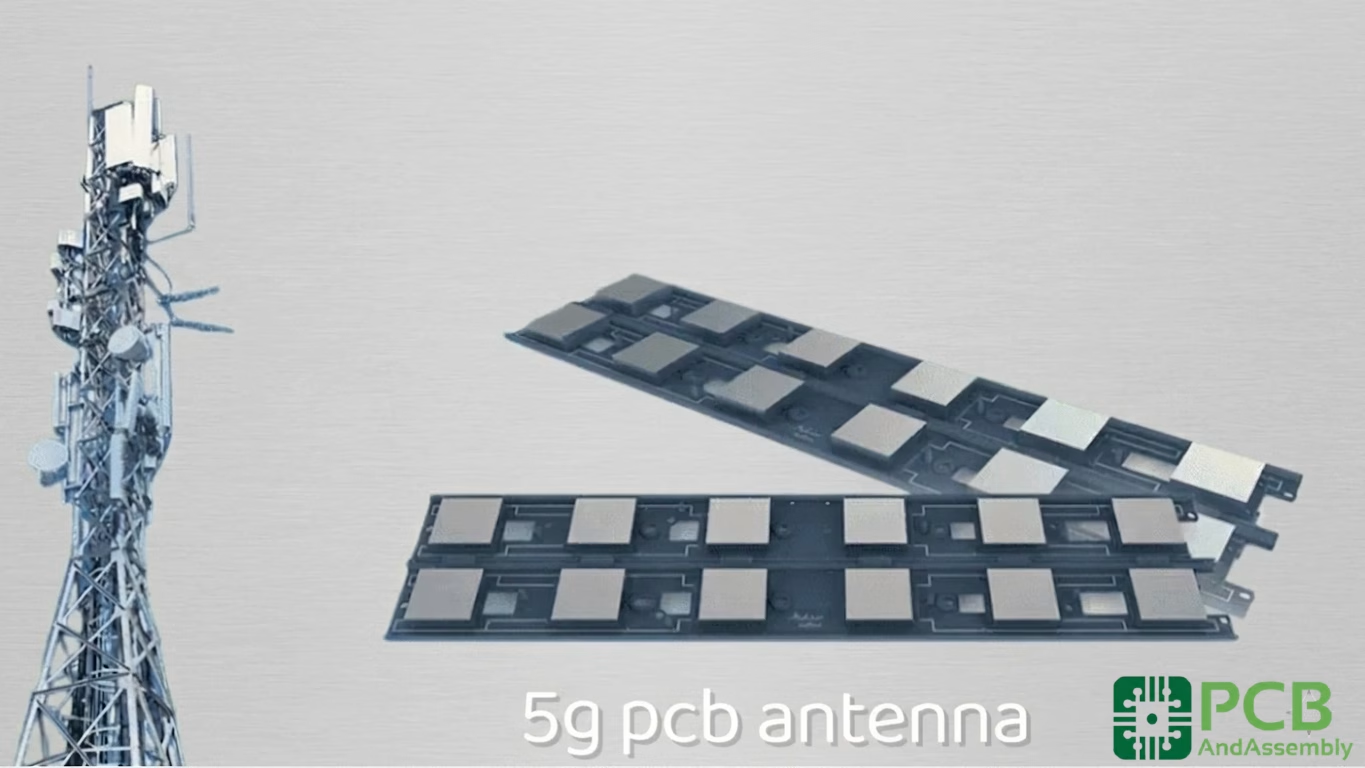
- 5G Infrastructure: 5G infrastructure: Base station antennas, power amplifiers, and beamforming networks operating at 24–39 GHz.
- Automotive Radar: Automotive radar: Both 24 GHz and 77 GHz radar systems rely on RO4350B’s temperature stability (−50°C to +150°C). The material’s tight Dk ensures the narrow beam accuracy that collision-avoidance systems require.
- Aerospace and Defense: Aerospace and defense: Radar systems, satellite communications, electronic warfare, and military radios leverage its stable performance for mission-critical links.
- Telecommunications: Telecommunications: Microwave backhaul antennas, LNBs, and satellite modems operating across Ku- and Ka-band.
- Industrial: Industrial: Precision test instruments and industrial sensing at microwave frequencies.
Frequently Asked Questions
Can I use standard FR-4 prepreg to bond RO4350B cores in a hybrid board?
Yes. Isola 370HR or Nelco N4000-13 prepregs work for bonding RO4350B to FR-4 layers. Design the stack-up symmetrically to prevent warping, and ensure the fabricator adjusts the press cycle to match curing parameters. For RF paths where prepreg is close to signal lines, use Rogers RO4450F bondply to maintain low loss.
Does RO4350B absorb moisture?
RO4350B has exceptionally low moisture absorption (< 0.06% under IPC test conditions—one-third or less of FR-4’s 0.15–0.25%). This prevents Dk/Df fluctuations in humid environments, maintaining stable impedance even in outdoor or condensing environments.
Why is the design Dk listed as 3.66 in some calculators when the datasheet says 3.48?
The datasheet Dk of 3.48 is the “process Dk,” measured via a clamped stripline test at 10 GHz. The “design Dk” of 3.66 accounts for standard electrodeposited copper roughness and the microstrip configuration—where some electric field fringing passes through air. Use the design Dk for accurate microstrip calculations.
Can RO4350B handle lead-free reflow temperatures?
Yes. With Tg > 280°C and Td of 390°C, RO4350B is fully compatible with standard lead-free reflow profiles peaking at 260°C. Its low Z-axis CTE ensures via reliability through these thermal cycles.
Is RO4350B suitable for 5G and millimeter-wave applications?
RO4350B performs well through approximately 40 GHz. It is widely used in 5G sub-6 GHz and 24–39 GHz mmWave bands. For 77 GHz automotive radar and above, Rogers offers the RO4350B VF variant, which is optimized for higher frequency stability.
Summary
Rogers RO4350B bridges the gap between high-frequency RF performance and standard manufacturing ease. By avoiding the processing nightmares of PTFE, it provides designers with a rigid, thermal-mechanically stable substrate that survives lead-free reflow and operates into the millimeter-wave spectrum.
Success with this material comes down to managing the details:
- Calculate impedance using the copper-roughness-adjusted design Dk (3.66 for standard ED foil on 20 mil core), not the raw datasheet value.
- Use hybrid stack-ups to minimize material cost while protecting RF layer performance.
- Select Immersion Silver or OSP surface finish—not ENIG—on traces above 5 GHz.
- Qualify your fabricator’s drill-hit limits and DFM rules before committing to production volumes.
Execute on these engineering principles and your high-frequency designs will deliver stable, repeatable performance with high production yields.

Get Quote Free