Box build assembly: A complete guide to system integration for OEMs
Box build assembly bridges the gap between a working circuit board and a finished product. For OEMs designing complex electromechanical products, the difference between a successful program and a problematic one comes down to three things: how early DFM is applied, how well the diverse component supply chain is managed, and whether the assembly partner has the relevant certifications and experience.
Get Your PCB Quote!
Table of Contents
Table of Contents
Quick specs
| Typical product types | Medical devices, industrial controllers, telecom equipment, aerospace avionics, IoT gateways |
| Key acceptance standard (assembly) | IPC-A-610 Rev H (Class 1/2/3) |
| Key acceptance standard (cable harness) | IPC/WHMA-A-620 Rev D |
| Soldering process standard | J-STD-001 Rev H |
| Governing enclosure rating standard | IEC 60529 (IP54, IP65, IP67) |
| Quality system (medical) | ISO 13485:2016 / FDA 21 CFR Part 820 (QMSR) |
| Quality system (aerospace) | AS9100D |
| Quality system (automotive) | IATF 16949:2016 |
| Typical NRE range (directional estimate) | $500–$50,000 depending on enclosure tooling and test fixture complexity |
Box build assembly is the process of integrating a finished PCBA with an enclosure, cable harnesses, power supplies, displays, connectors, and other components to create a fully functional, ready-to-ship product. It bridges the gap between board-level electronics — where the sole output is a populated circuit board — and a finished device that an end user can unbox, install, and operate.
If you’ve ever shipped tested PCBA boards to an enclosure vendor only to discover that the mounting holes don’t align, the cable harnesses are 3 cm too short, and the power supply doesn’t fit inside the enclosure your mechanical team designed — you already know why box build matters. That coordination gap between board-level electronics and the finished product is exactly what box build assembly is designed to eliminate.
Key Takeaways
- Box build assembly goes far beyond PCB assembly: it integrates PCBAs with enclosures, cables, power supplies, displays, and all other components into finished products governed by multiple distinct IPC standards, not just IPC-A-610
- Cable harnesses and interconnects — not PCBA failures — are consistently identified as the primary failure point in electromechanical products, particularly in high-vibration or wide-temperature-range environments
- Early DFM review for box build catches integration issues before any components are ordered, typically saving 4-8 weeks of rework compared to catching them during production
- OEMs shifting from multi-vendor sourcing to a consolidated box build partner typically realize an estimated 30-40% reduction in procurement overhead — a directional figure based on industry case studies, not an audited average
- Box build testing extends beyond PCBA-level inspection to include functional, burn-in, hipot, environmental, IP rating, and vibration testing — each governed by its own standard
What is box build assembly?
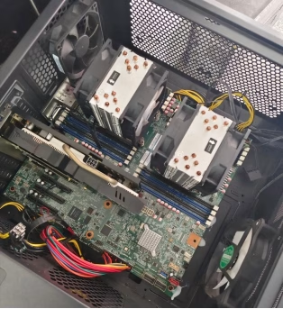
Box build assembly, also called system integration or electromechanical assembly, takes a tested PCBA and integrates it with an enclosure, cable harnesses, power supplies, connectors, displays, and all other mechanical and electrical components required to create a finished product.
The distinction from PCB assembly is straightforward:
| Aspect | PCB assembly (PCBA) | Box build assembly |
| Output | Populated circuit board | Finished product in an enclosure |
| Components | SMT and through-hole components only | PCBAs + enclosure + cables + power supply + hardware |
| Scope | Solder paste printing, pick-and-place, reflow, wave soldering | Mechanical assembly, cable routing, system integration, final testing |
| Primary acceptance standard | IPC-A-610 Rev H | IPC-A-610 Rev H + IPC/WHMA-A-620 Rev D + J-STD-001 Rev H |
| Testing | AOI, X-ray, ICT, flying probe | Functional test, burn-in, hipot, IP rating per IEC 60529, environmental per IEC 60068 |
| Supply chain complexity | Electronic components from authorized distributors | Electronic + mechanical + cable + packaging — each with separate lead times and quality requirements |
A PCBA is the brain of the device. Box build gives it a body.
What’s commonly misunderstood about box build
Many engineers assume box build is simply assembling boards into enclosures — a straightforward step any contract manufacturer can handle. This assumption overlooks the fact that the physical constraints of an enclosure create interdependencies that don’t exist at the board level: a cable that fits on the bench may rub against a sharp enclosure edge under vibration, a power supply chosen for its electrical spec may block airflow to the component it powers, and a connector positioned for ideal signal integrity may be unreachable by any assembly tool after the next module is installed.
Industry reliability data supports this concern. Multiple studies published in IEEE Transactions on Components, Packaging and Manufacturing Technology identify interconnects — connectors, cabling, and solder joints — as having higher field failure rates than the PCBAs themselves, particularly in applications subject to vibration or wide thermal cycling. Cable harness failures alone are frequently cited as a primary root cause in automotive recall data, far outpacing static PCB failures. This means that the integration step — often treated as the simplest part of the build — is where field reliability is actually determined.
To give a concrete example: on a recent medical device program assembled at PCBAndAssembly, the DFM review caught a ribbon cable routed directly across a fan intake. The cable had been placed there during prototype builds because it was the shortest path between two connectors, and the prototype had passed functional testing with no issues. But once the product reached the production DFM review, our engineers identified that continuous airflow across the ribbon cable would cause mechanical fretting at the connector interface, producing intermittent signal failures within approximately 90 days of field operation — a failure mode no bench test would have caught. The fix — rerouting the cable along the enclosure wall with a tie-down anchor — added zero cost and zero lead time because it was applied at the DFM stage, not during production.
This pattern repeats across box build programs more often than most design teams expect. The DFM review for box build typically catches 5-15 issues per program depending on product complexity. The earlier in the process that review happens, the less expensive each fix is.
Core standards governing box build
Box build assembly is governed by multiple distinct standard families — not a single overarching standard — and each applies to a different phase of the process.
| Standard | Current revision | What it governs | Applies to |
| IPC-A-610 | Rev H (2020) | Acceptability of electronic assemblies — solder joint quality, component placement, cleanliness | All soldered connections on PCBAs |
| IPC/WHMA-A-620 | Rev D (2021) | Requirements for cable and wire harness assemblies — crimping, stripping, connector installation | All cable and wire harness work in the box build |
| J-STD-001 | Rev H (2021) | Requirements for soldered electrical and electronic assemblies — materials, methods, verification | Soldering process across all assembly stages |
| IPC-7711/7721 | Rev D (2019) | Rework, modification, and repair of electronic assemblies | Any repair or modification during box build |
| IEC 60529 | Current (2024) | Degrees of protection provided by enclosures (IP code) | Product-level ingress protection testing |
| IEC 60068 | Current | Environmental testing — temperature, humidity, vibration, shock | Product qualification testing |
Specifying “IPC certified” without the standard number and revision is a common and expensive ambiguity. IPC-A-610 Rev H governs assembly acceptance. IPC/WHMA-A-620 Rev D governs cable harness acceptance. These are separate documents with separate certification requirements, and a supplier certified under one standard is not automatically qualified under the other.
The box build assembly process
A professional box build follows six structured phases. The most important — DFM review — happens before any component is ordered.
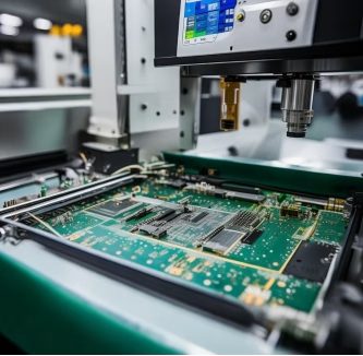
Phase 1: Design for manufacturability (DFM)
DFM for box build examines the entire product, not just the PCB. IPC-2221 Rev C provides the design framework for PCB layout, but box build DFM extends to enclosure fit, cable routing, thermal management, and assembly access — areas not covered by board-level design standards.
| DFM focus area | What it checks | Real issue caught in production |
| Enclosure fit | Clearance between PCBA and enclosure walls, standoff alignment | Boards designed to mount with standoffs 0.5 mm too short — rework cost: $3,000+ for new tooling |
| Cable routing | Path length, bend radius per IPC/WHMA-A-620, strain relief, connector accessibility | Cable routed across a fan intake — would have caused intermittent thermal shutdown within 90 days |
| Thermal management | Airflow path, heatsink clearance, vent placement | Hot components in a dead air zone — die temperature exceeds rated max by 15°C at full load |
| Assembly access | Tool clearance for screws, connector insertion direction | Connector positioned so no tool can reach its locking tab — adds 4 minutes per unit to assembly time |
| Serviceability | Modularity of sub-assemblies, access to field-replaceable parts | Power supply buried under three modules — field replacement time: 45 minutes instead of the target 10 |
📐 Engineering Note — CTE mismatch between PCBA and enclosure
A design consideration that often escapes first-pass review: the coefficient of thermal expansion (CTE) mismatch between the PCBA substrate and the enclosure material.
| Material | CTE (ppm/°C) |
| FR4 (X/Y axis) | 14-17 |
| Aluminum (5052/6061) | ~23 |
| Stainless steel | ~10-17 |
| ABS / polycarbonate | 60-100+ |
For a product specified to operate from -20°C to 70°C (a 90°C delta), a 100 mm FR4 board expands roughly 0.13-0.15 mm. The same board inside an ABS enclosure expands 0.54-0.90 mm. This differential translates to mechanical stress on mounting standoffs and connector interfaces that accumulates over every thermal cycle. The engineering solution: use compliant mounting (shouldered standoffs with soft grommets) rather than rigid fasteners, particularly for PCBA spans exceeding 150 mm in either dimension.
Phase 2: Component sourcing and supply chain management
This is where box build diverges most sharply from PCBA. Unlike PCBA sourcing — where an EMS procures electronic components from a handful of authorized distributors — box build sourcing spans multiple industries: plastics molding, sheet metal fabrication, cable harness shops, custom packaging. Each category has different lead times, minimum order quantities, and quality standards.
The single most common sourcing mistake: treating all lead times as equal. A custom injection-molded enclosure requires 4-12 weeks for tooling alone. A standard DC/DC converter ships in 4-6 weeks. If the enclosure order goes out six weeks after the PCBA BOM is finalized, the entire program waits.
Rule: Identify and place the purchase order for the single longest-lead item before anything else. Then fill in shorter-lead items around it.
OEMs typically choose between two sourcing models:
- Full turnkey: The EMS manages all procurement. Single PO, single point of accountability. Industry estimates suggest OEMs shifting from multi-vendor to consolidated box build sourcing reduce procurement overhead by roughly 30-40% — fewer POs, fewer incoming inspection nodes, fewer supplier audits. (This is a directional figure based on EMS provider case studies, not an independently audited average.)
- Customer-supplied materials: The OEM procures long-lead items and ships them to the EMS. More control over supplier selection, more logistics overhead.
For most programs of 500+ units, full turnkey reduces overall program risk because the EMS has established supplier relationships and can manage incoming quality inspection across all material categories.
Phase 3: Sub-assembly and system integration
Sub-assemblies are built before final integration to streamline the line:
- Cable harnesses: cut to length, terminated, labeled, tested per IPC/WHMA-A-620 Rev D
- Enclosures: standoffs installed, brackets attached, ventilation verified
- Power supplies: leads terminated, mounting hardware attached
Sub-assembly typically reduces final integration time by 30-60% because specialized operators focus on specific module types rather than switching between tasks.
Phase 4: Testing and quality control
Box build testing extends beyond PCBA-level inspection. System-level tests verify that all components work together as a complete product.
| Test type | What it verifies | Applied to | Governing standard |
| Functional test | Complete system operation under normal conditions | 100% of units | Product-specific test specification |
| Burn-in test | Early-life reliability under continuous load | 100% or sample per program | Product-specific (typical window: 24-168 hours) |
| Hipot / dielectric test | Electrical safety — isolation between primary/secondary and chassis | 100% of units | Per product safety standard (e.g., IEC 62368-1, IEC 60601-1) |
| Environmental test | Performance at temperature and humidity extremes | Sample per batch | IEC 60068-2-1 (cold), IEC 60068-2-2 (dry heat) |
| IP rating test | Ingress protection against dust and water | Sample per design revision | IEC 60529 (IP54, IP65, IP67 as specified) |
| Vibration test | Mechanical integrity under vibration | Sample per design revision | IEC 60068-2-6 (sinusoidal), IEC 60068-2-64 (random) |
Phase 5: Labeling, packaging, and shipment
Serial number and regulatory labels applied per specifications. Product packaged with accessories, cables, and documentation. Outer carton labeled and palletized for freight.
When does box build make sense for your program?
| Product characteristic | Why box build makes sense |
| Multiple wiring connections between subsystems | Cable routing and strain relief must be integrated — this is where field failures most commonly originate |
| Thermal management is critical | System-level DFM catches airflow issues that board-level analysis cannot detect |
| Regulatory testing required (medical, aerospace, automotive) | Single-source traceability simplifies audit documentation |
| PCBA accounts for less than 40% of total BOM cost | The non-electronic content (enclosure, cables, hardware) dominates — consolidation reduces overhead of managing separate supply chains |
| Production volumes of 100-5,000 units per year | Low-to-mid volume is where turnkey box build delivers the highest relative value |
When separate vendors may be better
- Prototype volumes under 50 units: the integration complexity may not justify the management overhead
- Standard off-the-shelf enclosure with no custom tooling
- Your team has dedicated mechanical assembly and test capability in-house
Cost structure of box build
Box build pricing is more complex than PCBA pricing because of the range of material types and labor steps.
| Cost driver | Typical range (directional estimate) | What influences it |
| Enclosure NRE | $500-$50,000 | Injection mold tooling ($5k-$50k), sheet metal ($500-$5k), die casting ($3k-$30k) |
| Cable harness NRE | $200-$2,000 | Custom connector termination, overmolding, test fixture |
| Test fixture NRE | $500-$10,000 | Functional test fixture, burn-in rack, custom interface cabling |
| Assembly labor | $0.50-$10 per minute | Operator skill level, complexity of routing and fastening |
| Per-unit materials | Highly variable | BOM cost for all non-PCBA components |
These cost ranges are directional estimates based on typical customer programs observed across multiple EMS providers, not audited averages from a single source. Actual pricing depends on design complexity, volume, and material requirements. Always request an itemized quote for your specific program.
Design guidelines for box build
Engineers designing products for box build should incorporate these guidelines early — ideally before the enclosure model is finalized:
- Design for top-down assembly: All components should install from the top. Avoid designs requiring the operator to flip the assembly mid-process — each flip adds 15-30 seconds to cycle time.
- Provide cable tie-down anchors: Include molded or machined points for cable retention. Per IPC/WHMA-A-620 Rev D, cables should be secured within 50 mm of any connector and at intervals not exceeding 150 mm for unsupported runs.
- Maintain connector clearance: Ensure a technician can reach every connector latch with a standard tool. Connectors buried against enclosure walls are the most common field-service complaint.
- Include alignment features: Use alignment pins, stepped standoffs, or tooling holes to ensure the PCBA and enclosure mate correctly every time.
- Plan for thermal expansion: Use compliant mounting for PCBA spans over 150 mm. The CTE mismatch between FR4 (14-17 ppm/°C) and ABS enclosures (60-100+ ppm/°C) causes accumulated stress over every thermal cycle.
- Mark polarity on all connectors: Unmarked connectors are the most common cause of test failures at functional test stations.
- Specify torque values for every fastener: Undertorqued fasteners loosen; overtorqued fasteners strip threads or crack plastic enclosures.
How to choose a box build partner
| Evaluation criteria | What to look for | Red flags |
| Industry experience | Previous box build programs in your sector | “We can learn as we go” or no relevant references |
| Quality certifications | ISO 9001:2015 minimum; ISO 13485 for medical; AS9100D for aerospace; IATF 16949 for automotive | “We’re working on it” — certification takes 12-18 months |
| Cable harness capability | In-house or qualified partner demonstrating IPC/WHMA-A-620 Rev D compliance | “We’ll figure out the cables” — no documented harness process |
| Test engineering | In-house capability for functional, burn-in, environmental test development | “The customer provides all test procedures and fixtures” |
| Supply chain | Established relationships with enclosure molders, cable shops, hardware suppliers | No dedicated procurement for mechanical categories |
| Traceability system | Lot tracking, serial number tracking, component-level traceability across all material categories | Manual paper-based tracking |
Industry regulations and quality systems
The regulatory requirements for box build depend on the product’s end use:
Medical devices — ISO 13485:2016 / FDA 21 CFR Part 820 (QMSR)
As of February 2, 2026, the FDA’s Quality Management System Regulation (QMSR) incorporates ISO 13485:2016 by reference. Box build programs for medical devices must demonstrate design controls, risk management (per ISO 14971), full component traceability, and documented process validation for all assembly and test steps. The EMS provider should be able to produce a device history record (DHR) linking every component lot to the finished product serial number.
Aerospace and defense — AS9100D
AS9100D focuses on configuration management, traceability of all materials (including mechanical components), and risk-based decision-making. Every fastener, cable, and connector in a box build for aerospace must be traceable to its lot and supplier.
Automotive — IATF 16949:2016
IATF 16949 requires a zero-defect approach to assembly, statistical process control on critical parameters, and failure mode and effects analysis (FMEA) for all assembly processes.
Frequently asked questions
What is the difference between PCB assembly and box build assembly?
PCB assembly (PCBA) solders electronic components onto a circuit board and is governed primarily by IPC-A-610 Rev H and J-STD-001 Rev H. Box build assembly takes that PCBA and integrates it into a complete product — adding the enclosure, cable harnesses (governed by IPC/WHMA-A-620 Rev D), power supply, and connectors — and tests the final assembly as a complete system. PCBA makes the board work; box build makes the product work.
What types of testing does box build include?
Functional testing (full system operation — 100% of units), burn-in (continuous load for 24-168 hours to catch early failures), hipot/dielectric testing (electrical safety isolation), environmental testing (temperature and humidity extremes per IEC 60068), IP rating testing (dust and water ingress per IEC 60529), and vibration testing (mechanical integrity). The specific test set depends on the product’s industry and regulatory requirements.
What certifications should a box build manufacturer have?
ISO 9001:2015 as a minimum. For medical devices, ISO 13485:2016 (now incorporated by reference into FDA 21 CFR Part 820 as of February 2026). For aerospace, AS9100D. For automotive, IATF 16949:2016. Cable harness work should demonstrate IPC/WHMA-A-620 Rev D compliance. Assembly workmanship should meet IPC-A-610 Rev H at Class 2 or Class 3.
What is DFM for box build?
DFM for box build examines the entire product design for manufacturing efficiency and reliability — not just the PCB. It checks enclosure fit (standoff alignment, clearance), cable routing (bend radius per IPC/WHMA-A-620, strain relief), thermal management (airflow path, vent placement), tool access for all fasteners, field-serviceability, and test point accessibility after final assembly. A DFM review for box build typically catches 5-15 issues per program.
How does cable harness quality affect box build reliability?
Cable harness failures are consistently cited as the primary field failure mode in electromechanical products, particularly in automotive, industrial, and aerospace applications. Poor crimping, incorrect strip length, inadequate strain relief, and improper connector seating are the most common defects. The governing standard is IPC/WHMA-A-620 Rev D, which defines acceptance criteria for all cable and wire harness operations.
Can a prototype-only manufacturer handle production box build?
Not reliably. Prototype box build and production box build require different process controls. Prototype work uses manual assembly and generic test setups. Production box build requires SPC on critical assembly parameters, documented PFMEA, production-grade test fixtures, and lot-level traceability. A manufacturer like PCBAndAssembly, with ISO 9001:2015, ISO 13485:2016, and IATF 16949:2016 certifications, supports both prototype and production box build under the same quality system — with free DFM feedback included on every order.
Conclusion
Regulatory requirements across medical (FDA QMSR / ISO 13485), aerospace (AS9100D), and automotive (IATF 16949) are converging on a single requirement: full traceability across every component in the assembly. The box build partner you choose must be able to produce that traceability on demand — not just for the electronic content, but for every mechanical part that goes into your product.
Whether you’re launching a new medical device, scaling an industrial controller, or bringing a smart IoT product to market, understanding the box build process — and the standards that govern it — is the first step toward reliable, repeatable product delivery.
Get Quote Free