Rogers RO4003C PCB:High-Frequency PCB Laminate Material Guide
Rogers RO4003C is a series of hydrocarbon laminates with a dielectric constant of 3.38 ± 0.05, designed for high-frequency applications up to gigahertz frequencies.
Get Your PCB Quote!
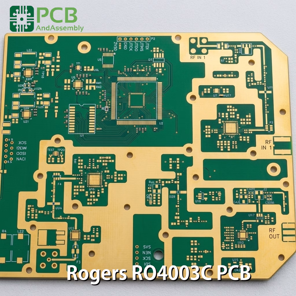
Table of Contents
- Introduzione
- Che cos'è il materiale ad alta frequenza RO4003C?
- Costanti dei materiali e specifiche tecniche
- Perché RO4003C non soddisfa gli standard di resistenza alla fiamma
- Perché FR-4 fallisce al di sopra dei 4 GHz
- Riduzione dei costi con soluzioni ibride a strati
- Linee guida per la fabbricazione e l'assemblaggio
- Controllo dell'impedenza e progettazione delle linee di trasmissione
- Errori di progettazione comuni da evitare
- Test e validazione
- Principali aree di applicazione
- Domande frequenti
- Sintesi
Introduction
If you have ever had a high-frequency design rejected at the final system-compliance stage, you know the pain of overlooking a material’s safety rating. I once watched an aerospace client write off a $40, 000 prototype run because they specified a Rogers RO4003C PCB instead of RO4350B, failing their mandatory UL 94 V-0 safety audit. While RO4003C offers exceptional RF performance, understanding its exact thermal, mechanical, and chemical boundaries is what keeps your yield high and your design compliant.
Today, you will learn everything you need to know about RO 4003C – from applications, benefits, features, properties, and many more.
What is RO4003C High-Frequency Material?
Rogers RO4003C is a proprietary hydrocarbon ceramic laminate designed to bridge the performance gap between low-cost FR-4 and high-performance PTFE (Teflon) substrates.
It behaves like FR-4 during drilling and plating, eliminating the aggressive sodium etching or plasma treatments required for PTFE. The material uses a thermoset resin system rather than a thermoplastic, ensuring dimensional stability during multi-layer lamination cycles.
The material is offered in two glass fabric styles—1080 and 1674—both engineered to meet identical electrical performance specifications, preventing unexpected impedance variations across different production lots.
- Thermoset hydrocarbon resin system filled with ceramic particles
- Woven fiberglass reinforcement using either 1080 or 1674 glass styles
- Non-brominated chemistry: environmentally friendly but non-flame-retardant
- Compatible with standard lead-free reflow profiles up to 260°C
- Direct compatibility with FR-4 manufacturing chemistry and equipment
- Not UL 94 V-0 rated — use RO4350Bif flame rating is required
Need PCB Manufacturing or Assembly?
Get a free quote within 24 hours. We specialize in prototype-to-production PCB/PCBA for hardware teams worldwide.
Material Constants and Technical Specifications
Designers frequently input generic dielectric constant (Dk) values into field solvers and wonder why their 50Ω traces measure at 44Ω post-fabrication.
You must design with the exact clamped Dk of 3.38 at 10 GHz while factoring in copper foil profile and resin content. For impedance calculations, use the design Dk of 3.55, which already accounts for copper roughness effects and real-world operating conditions.
Electrical Properties
| Property | Value | Design Significance |
| Dielectric Constant (Dk) | 3.38 ± 0.05 @ 10 GHz | Ensures stable impedance matching across microwave frequencies. |
| Design Dk (for calculations) | 3.55 | Use this value in impedance calculators to account for copper roughness. |
| Dissipation Factor (Df) | 0.0027 @ 10 GHz | Minimizes signal attenuation in high-speed, high-frequency channels. |
| Loss Tangent (tanδ) | 0.0021 @ 2.5 GHz | Low loss across the mid-microwave range. |
| Volume Resistivity | 1.7 × 10¹⁰ MΩ·cm | Excellent electrical isolation between traces. |
| Surface Resistivity | 4.2 × 10⁹ MΩ | Low surface leakage under humidity conditions. |
| TCDk (Thermal Coeff. of Dk) | +40 ppm/°C | Ensures phase and frequency stability across operating temperatures. |
Thermal Properties
| Property | Value | Notes |
| Glass Transition Temp (Tg) | >280°C (>536°F) | Maintains mechanical stability during high-temperature assembly. |
| Thermal Conductivity | 0.71 W/m·K | Improves heat dissipation for power amplifiers and transmitters. |
| CTE (X-axis) | 11 ppm/°C | Closely matches copper’s expansion rate to minimize trace stress. |
| CTE (Y-axis) | 14 ppm/°C | Prevents board warping during reflow. |
| CTE (Z-axis) | 46 ppm/°C | Reduces stress on plated through-holes (PTH) under thermal shock. |
| Decomposition Temp (Td) | 425°C (TGA) | Wide safety margin above lead-free solder processes. |
Mechanical Properties
| Property | Value | Notes |
| Moisture Absorption | 0.04% | Prevents delamination and maintains stable Dk in humid environments. |
| Peel Strength | 1.05 N/mm | After solder float; strong copper adhesion. |
| Flexural Strength | 276 MPa | Per IPC-TM-650 2.4.4. |
| Density | 1.79 g/cm³ | — |
| Copper Peel | 6.0 lb/in | After thermal stress; suitable for fine-pitch SMT. |
Standard Available Thicknesses and Copper Weights
| Thickness (mil) | Thickness (mm) | Copper Weights Available |
| 8 | 0.203 | 0.5 oz (17μm), 1.0 oz (35μm) |
| 12 | 0.305 | 0.5 oz, 1.0 oz, 2.0 oz |
| 16 | 0.406 | 0.5 oz, 1.0 oz, 2.0 oz |
| 20 | 0.508 | 0.5 oz, 1.0 oz, 2.0 oz |
| 32 | 0.813 | 1.0 oz, 2.0 oz |
| 60 | 1.524 | 1.0 oz, 2.0 oz |
Panel sizes: 12″×18″ (305×457mm) or 24″×18″ (610×457mm), depending on the fabricator.
Why RO4003C Fails Flame Retardancy Standards
The most critical decision crossroads in high-frequency laminate selection is the flame rating. RO4003C and RO4350B are virtually identical electrically, but RO4003C lacks the brominated flame retardants needed to achieve a UL 94 V-0 rating. If your product requires UL certification for commercial sale or deployment in public infrastructure, substituting RO4003C without a redesign will halt your project.
Because RO4350B has a slightly higher Dk (3.48 vs. 3.38), trace widths must be recalculated to maintain controlled impedance when transitioning between the two materials. The table below outlines the trade-offs:
| Property / Feature | Rogers RO4003C | Rogers RO4350B |
| Dielectric Constant (Dk) | 3.38 ± 0.05 | 3.48 ± 0.05 |
| Design Dk | 3.55 | 3.66 |
| Dissipation Factor (Df) | 0.0027 @ 10 GHz | 0.0037 @ 10 GHz |
| UL 94 V-0 Rated | No | Yes |
| Brominated Formulation | No (halogen-free) | Yes |
| Thermal Conductivity | 0.71 W/m·K | 0.69 W/m·K |
| Material Cost Index | Lower | Higher |
| Primary Use Cases | RF labs, non-UL consumer RF, RFID, LNAs, passive networks | 5G base stations, automotive radar, UL-certified systems, power amplifiers |
Decision guide:
- Choose RO4003C when the lowest possible dissipation factor is required and UL 94 V-0 certification is not a system-level requirement.
- Choose RO4003C for prototype runs, RF testing fixtures, or high-performance laboratory equipment where halogen-free construction is an advantage.
- Choose RO4350B if the design must be deployed in commercial telecom networks, power grids, or any system requiring UL safety approval.
- Never directly substitute RO4003C for RO4350B in an active design without re-simulating microstrip and stripline widths — the 0.10 Dk difference will shift your impedance.
Why FR-4 Fails Above 4 GHz
Below 1–2 GHz, FR-4 works fine for most applications. Between 2–6 GHz, you will start noticing degradation. Above 6 GHz, RO4003C becomes almost essential for reliable performance.
At frequencies above 4 GHz, FR-4’s high loss tangent (typically 0.020) turns RF energy into thermal energy. Over a 3-inch microstrip trace at 10 GHz, this translates to roughly 0.5 dB of unnecessary signal degradation that can easily ruin a link budget. Standard FR-4 materials also suffer from a volatile dielectric constant across temperature and frequency: as the board warms under load, Dk shifts and detunes filters and transmission lines.
| Property | Standard FR-4 | Rogers RO4003C |
| Dielectric Constant (Dk) | 4.2–4.8 (varies with frequency) | 3.38 ± 0.05 |
| Dk Tolerance | ±0.20 to ±0.35 | ±0.05 |
| Dk Stability vs. Temperature | >200 ppm/°C | 40 ppm/°C |
| Loss Tangent (Df) @ 10 GHz | 0.015 to 0.025 | 0.0027 |
| Glass Transition Temp (Tg) | 130°C to 170°C | >280°C |
| Z-Axis CTE | 50 to 70 ppm/°C | 46 ppm/°C |
| Thermal Conductivity | 0.1–0.5 W/m·K | 0.71 W/m·K |
| Moisture Absorption | 0.10–0.20% | 0.04% |
| Cost | Baseline | 3–5× FR-4 |
Reducing Cost with Hybrid Stackups
There is no need to pay for a full multilayer Rogers board when only the outer layers carry high-frequency signals. Hybrid stackups—where RO4003C is used on the outer layers and FR-4 is used on the inner layers—provide the ideal balance of RF performance and manufacturing economy. Route critical RF microstrips on the low-loss Rogers material while routing low-speed control lines and power distribution through cheaper FR-4 cores.
When designing a hybrid stackup, always account for the different curing temperatures and CTE profiles of the two materials. Multilayer hybrid boards can warp during reflow if copper density and material thicknesses are not balanced symmetrically across the stackup’s center line.
4-Layer Hybrid Stackup Example (RO4003C + FR-4)
| Layer | Material | Thickness | Function |
| L1 (Top) | Rogers RO4003C Core | 0.508 mm (20 mil) | RF microstrips, coplanar waveguides, high-speed differential pairs |
| Dielectric 1–2 | Rogers RO4450F Prepreg | 0.101 mm (4 mil) | Bonding layer optimized for RF laminate systems |
| L2 | Copper Foil (Ground) | 0.035 mm (1 oz) | Continuous RF reference plane |
| Dielectric 2–3 | FR-4 Core | 0.711 mm (28 mil) | Mechanical rigidity, low-frequency isolation |
| L3 | Copper Foil (Power/Signals) | 0.035 mm (1 oz) | DC power planes, low-speed digital control lines |
| Dielectric 3–4 | FR-4 Prepreg (e.g., 2116) | 0.101 mm (4 mil) | Standard cost-effective bonding layer |
| L4 (Bottom) | FR-4 Core (or RO4003C if symmetrical) | 0.508 mm (20 mil) | Secondary digital signals, power distribution, thermal ground pad |
Critical rules for hybrid stackups:
- Keep the stackup mechanically symmetrical from top to bottom to prevent warping during lead-free lamination and reflow cycles.
- Route RF signals on cores, not prepreg — the RO4003C core has tighter Dk control than any prepreg material.
- Use Rogers RO4450-series prepregs (e.g., RO4450F) when bonding RO4003C cores to ensure material compatibility.
- Keep high-frequency ground return paths continuous on Layer 2, directly beneath the RO4003C microstrip layer, with no splits or slots.
- Use thermal relief vias under high-power components to transfer heat through FR-4 inner layers to the bottom of the board.
- Coordinate early with your PCB fabricator to verify standard panel sizes and prepreg availability before finalizing your stackup.
6-Layer Advanced Hybrid Example
For more complex designs with multiple RF chains, a symmetric 6-layer hybrid provides RF routing on both outer layers and maximizes channel density:
| Layer | Material | Thickness | Function |
| L1 (Top) | Rogers RO4003C Core | 0.305 mm (12 mil) | RF signals |
| Dielectric 1–2 | Rogers RO4450B Prepreg | 0.101 mm (4 mil) | RF-compatible bondply |
| L2 | Copper (Ground) | 0.035 mm (1 oz) | RF ground plane |
| Dielectric 2–3 | FR-4 High-Tg Core | 0.254 mm (10 mil) | Digital signals isolation |
| L3 | Copper (Power Plane) | 0.035 mm (1 oz) | DC power distribution |
| Dielectric 3–4 | FR-4 Prepreg | 0.101 mm (4 mil) | Standard bonding layer |
| L4 | Copper (Digital) | 0.035 mm (1 oz) | Low-speed digital routing |
| Dielectric 4–5 | Rogers RO4450B Prepreg | 0.101 mm (4 mil) | RF-compatible bondply |
| L5 | Copper (Ground) | 0.035 mm (1 oz) | RF ground plane |
| L6 (Bottom) | Rogers RO4003C Core | 0.305 mm (12 mil) | RF signals (symmetric) |
Fabrication and Assembly Guidelines
Unlike PTFE-based materials, which require specialized chemical treatments such as sodium naphthenate to prepare hole walls for soldering, RO4003C behaves similarly to standard FR-4 in the fab shop. Standard tooling, chemical desmear lines, and plating baths can be used without modification, dramatically lowering fabricator tooling setup charges and decreasing prototype lead times.
Drilling Parameters
| Parameter | Recommendation |
| Surface Speed | <500 SFM |
| Chip Load | >0.002″ (0.05 mm) |
| Stack Height | <70% of flute length |
| Entry Material | Standard aluminum or phenolic |
| Drill Type | Carbide drills; adjust feed rates to prevent fiber breakout in ceramic filler |
Surface Finish Recommendations
For fine-pitch SMT and RF performance, specify Electroless Nickel Immersion Gold (ENIG) or Electroless Nickel Electroless Palladium Immersion Gold (ENEPIG). Standard Hot Air Solder Leveling (HASL) produces uneven surface topographies that can disrupt impedance control and degrade signal performance at millimeter-wave frequencies.
Copper Foil Options
| Foil Type | Notes |
| Standard Electrodeposited (ED) | Works for most applications up to ~20 GHz. |
| LoPro (Reverse Treated / Low-Profile) | Reduces insertion loss by improving copper-dielectric interface smoothness. Can reduce insertion loss by 10–15% at 40 GHz. Adds approximately 0.7 mil (18 μm) per core. Recommended above 20 GHz. |
Assembly and Processing Notes
- Specify ENIG or ENEPIG surface finishes for superior RF coplanarity and long shelf life.
- Keep trace tolerances to ±10% or tighter for controlled-impedance lines operating above 5 GHz.
- Avoid standard HASL finishes on transmission lines above 2 GHz to prevent skin-effect losses caused by irregular solder thickness.
- No plasma treatment or sodium etch required — standard soldering processes apply directly.
- Clean all assembly fluxes thoroughly to prevent moisture trapping, which can degrade the low loss tangent of the substrate.
- Include these notes in your fab drawing: Rogers RO4003C per IPC-4103/10; Dk tolerance ±0.05; standard FR-4 processing parameters acceptable; no special through-hole preparation required.
Impedance Control and Transmission Line Design
Getting impedance right on RO4003C requires understanding a few nuances that frequently trip up designers.
Microstrip vs. Grounded Coplanar Waveguide (GCPW)
Both transmission line structures work well on RO4003C, but they behave differently:
- Microstrip is simpler to design and fabricate. A 50Ω line on 20-mil RO4003C with 1 oz copper is approximately 45 mils wide, though the exact value depends on copper surface finish and manufacturing tolerances.
- GCPW (Grounded Coplanar Waveguide) offers better isolation between adjacent traces and tighter ground return paths. However, GCPW is more sensitive to manufacturing variations in the gap between signal and ground coplanar conductors.
Calculation Tips
- Start with the design Dk (3.55), not the process Dk (3.38). The design value already accounts for copper roughness effects.
- Factor in copper plating thickness. After plating, ‘1 oz’ copper is typically 1.2–1.4 oz, which affects final impedance.
- Model at your operating frequency. RO4003C’s Dk is stable but shifts slightly with frequency — at 77 GHz, Dk may be closer to 3.45.
- Specify ±10% impedance tolerance for production boards. Tighten to ±5% only after validating capability with your fab house.
- For solder mask over RF traces: solder mask increases effective Dk and dielectric losses. For critical RF traces, apply solder mask only at SMT pad locations and leave transmission line regions exposed.
Glass Weave Effects
RO4003C uses woven glass reinforcement (1080 or 1674 styles), which creates slight Dk variations depending on whether a trace runs over glass or resin. For signals above 20 GHz or high-precision applications, consider:
- Routing traces at 45° angles relative to the weave pattern.
- Using narrower traces that average over multiple weave periods.
- Specifying spread glass or PTFE-based materials for the most critical layers.
Via Design Considerations
- Avoid via aspect ratios greater than 8:1.
- Use thermal relief on power plane connections.
- Consider via backdrilling for high-frequency signals to reduce stub resonance.
- For 77 GHz automotive radar, via transitions are critical — use full-wave EM simulation and add ground vias surrounding each signal via.
Common Design Mistakes to Avoid
| Mistake | What Goes Wrong & How to Avoid It |
| Using process Dk (3.38) for calculations | Traces come out too narrow and impedances run high. Always use the design Dk (3.55) for impedance calculations. |
| Ignoring copper surface roughness | Standard ED copper increases effective Dk and insertion loss, especially above 10 GHz. Specify LoPro foil for designs above 20 GHz. |
| Placing RF traces on prepreg layers | Prepreg has looser Dk tolerances than core material. Always route RF signals on the RO4003C laminate core. |
| Neglecting via transitions at mmWave | Via inductance destroys matching at 77 GHz and above. Use full-wave EM simulation for via transitions — not optional. |
| Over-specifying impedance tolerances | ±3% tolerance drives cost significantly. Most designs work fine at ±10%. Tighten only when simulation confirms necessity. |
| Forgetting assembly impacts | RO4003C is more transparent to IR reflow ovens than FR-4. Monitor thermal profiles carefully — the board may heat differently during assembly. |
Testing and Validation
Once boards arrive, proper validation ensures they meet specifications before production ramp.
| Test | Method & Acceptance Criteria |
| Impedance Verification | Request TDR (Time Domain Reflectometry) coupons from your manufacturer. Typical acceptance: ±10% of design target. |
| Insertion Loss | Measure S21 with a VNA. RO4003C should show ~0.02–0.03 dB/inch at 10 GHz for 50Ω microstrip. |
| Return Loss | Measure S11. Well-designed 50Ω lines should achieve better than 20 dB return loss across the operating band. |
| Environmental Testing | Validate performance across temperature (−40°C to +85°C or wider) for automotive and aerospace applications. Verify TCDk compliance. |
Key Application Areas
| Application | Why RO4003C Is Preferred |
| 5G / Wireless Infrastructure | Low loss and stable Dk at 28 GHz and 39 GHz; tight phase matching for massive MIMO antenna arrays; low TCDk for outdoor thermal cycling. |
| Automotive Radar (ADAS) | Stable electrical performance from −40°C to +85°C; supports 24 GHz and 77 GHz radar; low TCDk keeps antenna resonant frequency stable across climatic extremes. |
| Aerospace / Satellite | Low moisture absorption (0.04%) for humidity cycling; reliable under harsh conditions; outgassing characteristics suitable for many spacecraft applications. |
| RF Test & Measurement | Tight Dk tolerance (±0.05) ensures test fixtures introduce minimal systematic error in VNAs, signal generators, and calibration standards. |
| Consumer Wireless (Premium) | Improved sensitivity and range for Wi-Fi 6E routers, IoT gateways, and flagship wireless front-end modules above 6 GHz. |
Frequently Asked Questions
Q1: Can I use standard FR-4 prepreg to bond Rogers RO4003C cores?
Yes, high-Tg FR-4 prepregs can be used in hybrid stackups. However, you must ensure the fabrication house balances the lamination thermal cycles. For high-reliability and critical RF applications, Rogers RO4400-series prepregs are recommended for best material compatibility.
Q2: Does RO4003C contain halogens or bromine?
No. RO4003C is a non-brominated, halogen-free material. Because it lacks flame retardants, it does not carry a UL 94 V-0 flame rating. If that rating is required, design with RO4350B or RO4835.
Q3: How does copper surface roughness affect RF performance?
RO4003C is available with standard electrodeposited (ED) copper or low-profile (LoPro) copper. At frequencies above 10 GHz, surface roughness causes skin-effect losses. For millimeter-wave designs above 20 GHz, specifying LoPro copper can reduce insertion loss by 10–15% at 40 GHz.
Q4: What is the maximum operating frequency for an RO4003C design?
RO4003C performs reliably up to 77 GHz and beyond (used in automotive radar), with most designs concentrated in the 2–40 GHz range. Above 20 GHz, copper surface roughness management becomes increasingly important. For the most demanding mmWave applications, evaluate materials with an even lower dissipation factor.
Q5: How does moisture affect RO4003C performance?
RO4003C’s moisture absorption is 0.04% — significantly better than FR-4’s typical 0.10–0.20%. Dielectric constant and loss tangent remain stable even in humid environments, making it advantageous for outdoor equipment, satellite systems, and marine electronics.
Q6: Can RO4003C be used above 40 GHz?
Yes, RO4003C maintains stable performance at 77 GHz and is widely used in automotive radar applications at that frequency. At mmWave frequencies, copper surface roughness becomes the dominant loss mechanism — specify LoPro foil for frequencies above 40 GHz. For the most extreme mmWave frequencies, consider Rogers materials with lower Df such as RO3003 or PTFE-based options.
Summary
RO4003C has earned its place as the workhorse of high-frequency circuit design. It delivers the electrical performance needed for demanding RF and microwave applications while remaining fully compatible with standard PCB manufacturing processes.
For specialized RF prototype systems and laboratory equipment where UL 94 V-0 certification is not a requirement, RO4003C offers a superior loss profile at a lower cost than RO4350B — exploit it accordingly.
Depending on your unique application requirements, PCBAndAssembly offers a range of Rogers PCB laminates.
Contact us today for all your RO 4003C PCBs from China.

Get Quote Free