Circuit Card Assembly: PCBA Process, Cost, and Manufacturer Guide
Learn how circuit card assembly works, from SMT and through-hole assembly to testing, quality control, cost factors, and choosing a PCB assembly manufacturer.
Get Your PCB Quote!
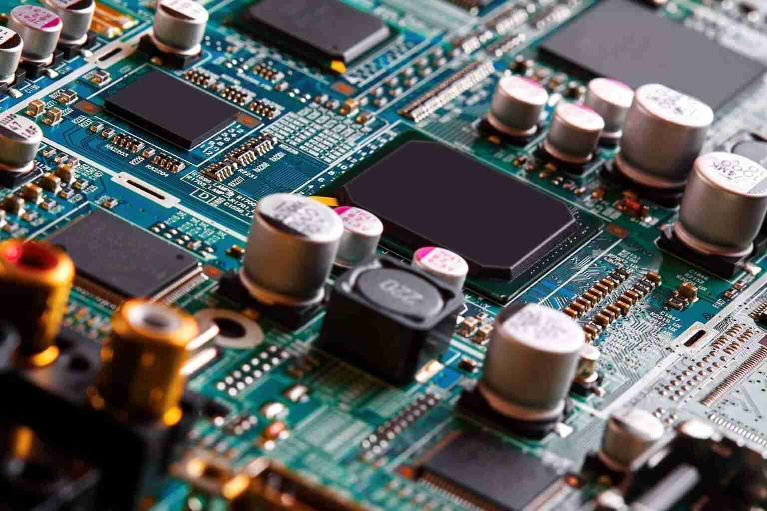
Table of Contents
- Circuit card assembly at a glance
- What Is Circuit Card Assembly?
- Circuit Card Assembly vs PCB Board Assembly vs PCBA
- Circuit Card Assembly Process
- SMT, Through-Hole, and Mixed Assembly
- Testing and Quality Control in Circuit Card Assembly
- Circuit Card Assembly Cost Factors
- How to Choose a Circuit Card Assembly Manufacturer
- Service Matching Guide
- Why Choose OrinewPCB for Circuit Card Assembly
- FAQ About Circuit Card Assembly
- Conclusion
Table of Contents
- Circuit card assembly at a glance
- What Is Circuit Card Assembly?
- Circuit Card Assembly vs PCB Board Assembly vs PCBA
- Circuit Card Assembly Process
- SMT, Through-Hole, and Mixed Assembly
- Testing and Quality Control in Circuit Card Assembly
- Circuit Card Assembly Cost Factors
- How to Choose a Circuit Card Assembly Manufacturer
- Service Matching Guide
- Why Choose OrinewPCB for Circuit Card Assembly
- FAQ About Circuit Card Assembly
- Conclusion
If you’re sourcing circuit card assembly services for the first time, the terminology alone can be confusing — circuit card assembly, PCB board assembly, PCBA, electronic assembly. These terms get used interchangeably, but they carry subtle differences in meaning, buyer intent, and technical scope.
This guide cuts through the confusion. It covers what circuit card assembly actually involves, how it differs from related terms, the step-by-step assembly process, testing standards, cost factors, and how to choose a manufacturer that matches your project requirements.
Circuit card assembly at a glance
| Item | What it means in a real project |
| Input package | Gerbers or ODB++, BOM, pick-and-place data, assembly drawings, and revision information |
| Main processes | SMT placement and reflow, THT insertion, selective or wave soldering, and manual operations where required |
| Inspection | Solder paste inspection (SPI), automated optical inspection (AOI), and X-ray for hidden joints or other risk areas |
| Electrical validation | In-circuit test (ICT), flying probe, functional test (FCT), or a combination selected for the product and volume |
| Quality reference | IPC-A-610J for post-assembly acceptability, used with J-STD-001J for soldered assembly requirements |
| Commercial output | A tested PCBA, inspection records, test data, and a documented disposition for any nonconformance |
What Is Circuit Card Assembly?
Circuit card assembly (CCA) is the process of mounting, soldering, inspecting, and testing electronic components onto a printed circuit board to create a functional electronic assembly. It covers the full sequence of operations that transform a bare PCB into a working circuit board ready for integration into an electronic product.
The term CCA is most commonly used in aerospace, defense, medical, and industrial electronics — sectors where reliability documentation, traceability, and formal quality standards are non-negotiable. In consumer electronics and general manufacturing, the same process is typically called PCBA (Printed Circuit Board Assembly).
Regardless of terminology, the core components of a circuit card assembly remain the same:
| Component | Function | Typical Materials |
| Substrate | Structural base for mounting components | FR-4, polyimide, PTFE, aluminum, ceramic |
| Copper traces | Electrical pathways between components | 0.5 oz to 2 oz electrodeposited copper |
| Solder mask | Protective layer preventing shorts and oxidation | Liquid photoimageable (LPI) green, blue, black, white |
| Silkscreen | Reference designators, polarity marks, logos | White or yellow epoxy ink |
| Solder joints | Mechanical and electrical connection | SAC305 (lead-free) or Sn63Pb37 (leaded) |
| Components | Active and passive electronic parts | ICs, resistors, capacitors, connectors, inductors |
| Surface finish | Protects exposed copper, ensures solderability | HASL, ENIG, OSP, Immersion Silver, Immersion Tin |
Circuit Card Assembly vs PCB Board Assembly vs PCBA
Understanding the terminology helps you search for the right service and communicate clearly with manufacturers.
| Term | Meaning | Typical Buyer Intent |
| Circuit card assembly (CCA) | Fully assembled circuit board with components soldered and tested | Seeking a manufacturer with formal quality systems for regulated industries |
| PCB board assembly | General term for assembling components onto a printed circuit board | Looking for PCB assembly services, often less specific |
| PCBA | Printed circuit board assembly — the finished product after assembly | Common in sourcing, procurement, and manufacturing contexts |
| Electronic assembly | Broader term covering PCB assembly, box build, cable harnesses, and final product integration | Seeking a full-service manufacturing partner beyond just board assembly |
In practice, the manufacturing process for all four terms is nearly identical — the differences lie in scope, industry conventions, and the level of documentation required.
Circuit Card Assembly Process
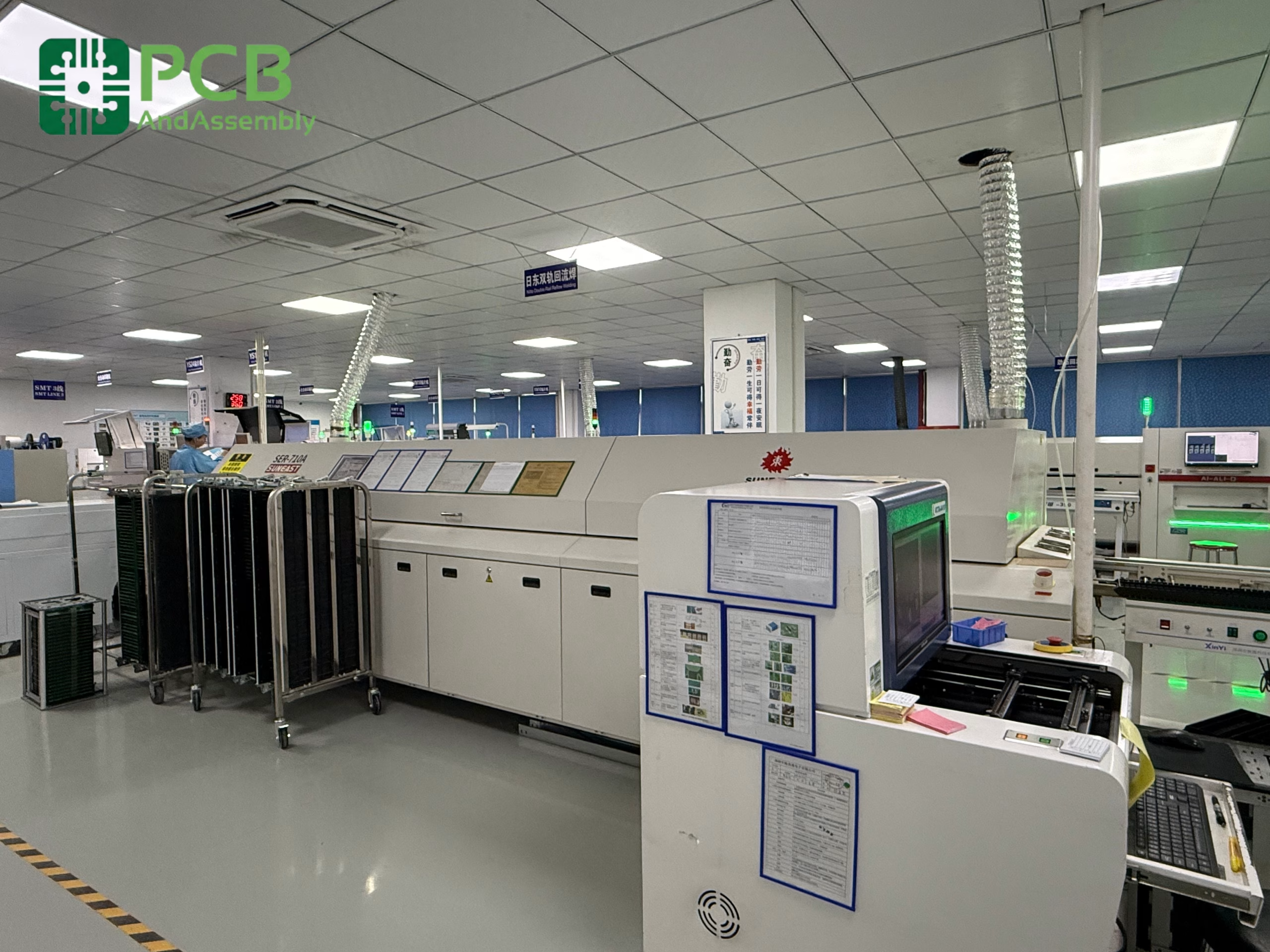
The circuit card assembly process follows a structured sequence of steps. Each step has a defined purpose and quality check.
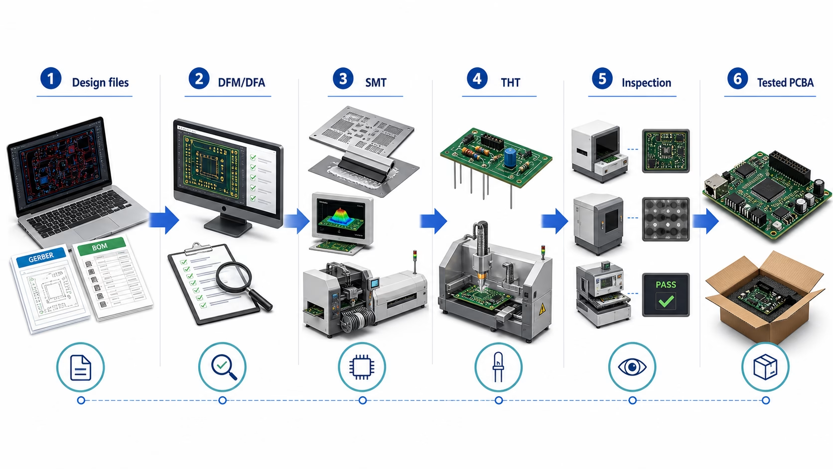
| Step | What Happens | Why It Matters |
| 1. DFM review | Gerber, BOM, and assembly files are reviewed by manufacturing engineers | Catches design issues before production — saves time and cost |
| 2. Solder paste printing | Solder paste is applied through a stainless steel stencil onto SMT pads | Controls solder volume, directly affects joint quality |
| 3. Solder paste inspection (SPI) | Automated 3D inspection verifies paste volume, height, and registration | Prevents defects caused by insufficient or excessive paste |
| 4. Pick-and-place | Components are placed by high-speed automated machines | Placement accuracy (±25–50 µm) determines assembly yield |
| 5. Reflow soldering | The board passes through a multi-zone reflow oven | Creates reliable SMT solder joints with controlled thermal profile |
| 6. Through-hole soldering | Leaded components are soldered via wave or selective soldering | Provides stronger mechanical joints for connectors and high-stress parts |
| 7. Cleaning | Flux residues are removed (unless using no-clean flux) | Prevents leakage currents and corrosion over product lifetime |
| 8. AOI / X-ray inspection | Automated optical and X-ray inspection checks for defects | Finds solder bridging, insufficient solder, BGA voids, and misalignments |
| 9. ICT / functional test | Electrical testing verifies circuit functionality | Confirms the assembly operates within specification |
| 10. Final inspection | Visual and dimensional check before packaging | Reduces field failure risk and ensures shipment quality |
Temperature Profile in Reflow Soldering
A typical lead-free reflow profile for SAC305 solder paste follows four zones:
| Zone | Temperature Range | Duration | Purpose |
| Preheat | 25°C → 150°C | 60–90 seconds | Gradual heating prevents thermal shock |
| Soak | 150°C → 200°C | 60–120 seconds | Activates flux, equalizes board temperature |
| Reflow | 217°C peak (245–260°C) | 30–60 seconds above liquidus | Forms metallurgical solder joint |
| Cooling | Peak → < 100°C | 2–4°C/second ramp-down | Solidifies joints, minimizes intermetallic growth |
SMT, Through-Hole, and Mixed Assembly
Circuit card assembly uses three primary soldering techniques. The choice depends on component types, mechanical requirements, and production volume.
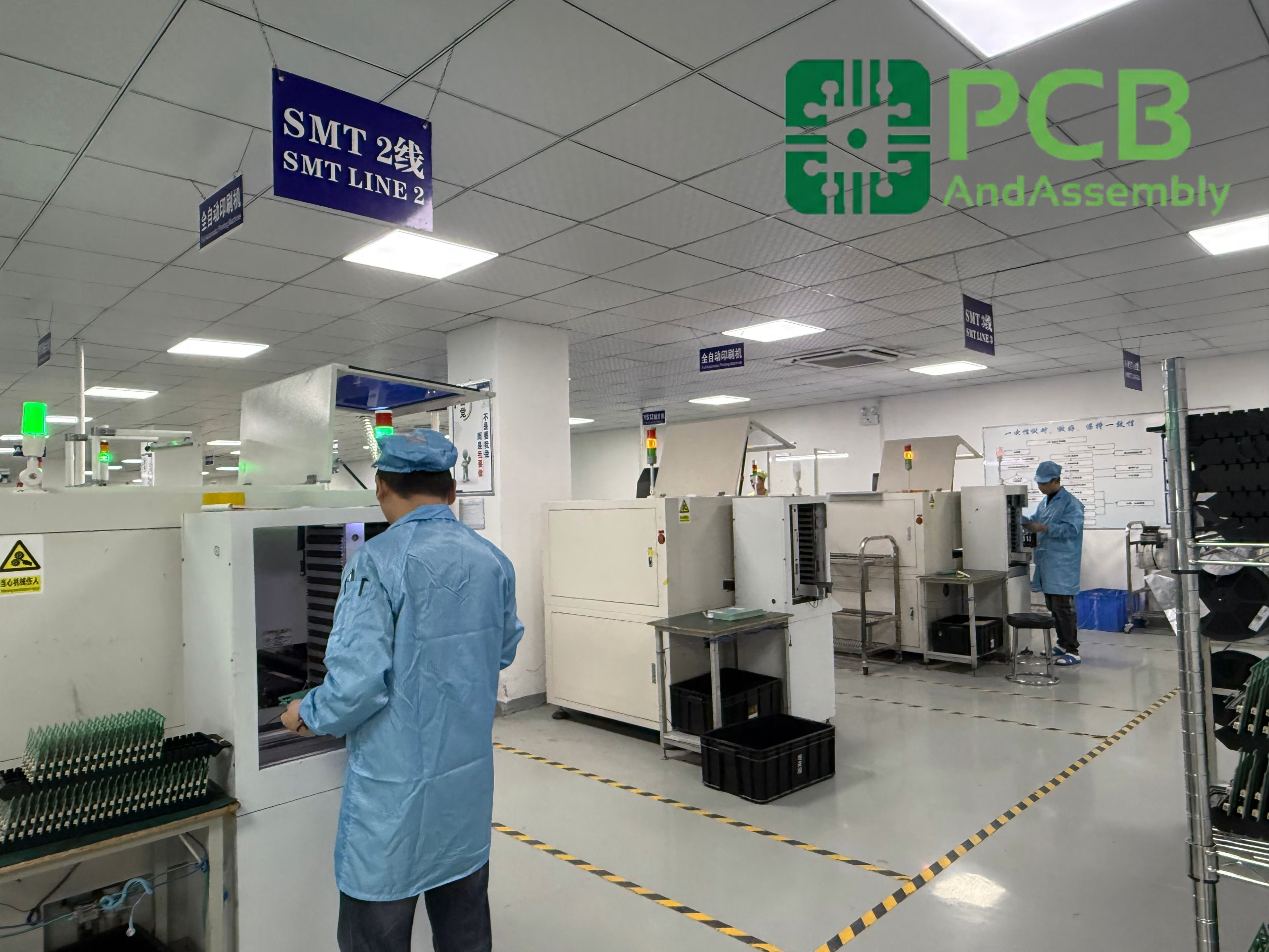
Surface Mount Technology (SMT)
SMT components are placed directly onto pads on the board surface and soldered in a reflow oven. SMT accounts for roughly 90% of all electronic assemblies today.
| Advantage | Limitation |
| Higher component density per board area | Weaker mechanical retention than through-hole |
| Faster automated placement | Difficult to hand-solder for rework |
| Lower cost per joint at volume | Requires precise stencil and paste control |
| Components available on both board sides | Thermal management can be challenging for power components |
Through-Hole Technology (THT)
Through-hole components have leads that pass through drilled holes and are soldered on the opposite side. Wave soldering and selective soldering are the primary methods.
| Advantage | Limitation |
| Superior mechanical strength for connectors and heavy parts | Lower component density — holes consume board space |
| Better thermal and power handling capability | Higher assembly cost per joint |
| Easier manual assembly and rework | Requires drilling and plating of every hole |
| Preferred for high-reliability and high-vibration environments | Slower production throughput |
Mixed Assembly
Most modern circuit card assemblies are mixed — they combine SMT components with a smaller number of through-hole parts such as connectors, terminal blocks, transformers, and electrolytic capacitors.
The standard process sequence for mixed assemblies is:
- Solder paste printing on the top side
- SMT placement and reflow
- Through-hole component insertion
- Wave or selective soldering (bottom side only)
- Inspection and test
Testing and Quality Control in Circuit Card Assembly
Testing is not a single step — it’s a multi-stage process that catches defects at different points in production.
Automated Optical Inspection (AOI)
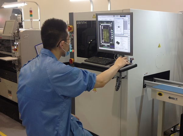
AOI uses high-resolution cameras to scan the board after reflow. It detects:
- Missing or misaligned components
- Solder bridging
- Insufficient or excessive solder
- Tombstoned components (one end lifted)
- Wrong polarity or orientation
Limitation: AOI cannot see under components — hidden joints on BGAs, QFNs, and similar packages are invisible to optical cameras.
X-Ray Inspection (AXI)
X-ray inspection is required when AOI cannot see the solder joints. It is essential for:
- BGA and QFN packages with hidden ball/pad arrays
- Components with thermal pads underneath
- High-reliability assemblies requiring voiding percentage verification
- Double-sided assemblies where bottom-side joints are obscured
X-ray reveals solder voids, bridging under components, head-in-pillow defects, and insufficient solder ball collapse.
In-Circuit Testing (ICT)
ICT uses a custom bed-of-nails fixture to contact test points on the board. It verifies:
- Correct component values (resistance, capacitance, inductance)
- Diode and transistor orientation
- Power and ground continuity
- IC pin connectivity
Trade-off: ICT provides the highest test coverage (typically 85–95%) but requires a custom fixture that costs 500-3,000 and takes 2–3 weeks to build. Best for production volumes above 500 units.
Flying Probe Testing
Flying probe testers use moving probes instead of a fixture. They are ideal for:
- Prototype and low-volume production
- Complex boards with limited test points
- Quick-turn assemblies where fixture build time is unacceptable
Trade-off: Slower than ICT (tests 5–10 points/second vs. hundreds/second with ICT) but no fixture cost and zero lead time.
Functional Testing (FCT)
Functional testing powers up the board and simulates its end-use environment. It confirms:
- Power-up sequence and current draw
- Communication interfaces (I2C, SPI, USB, Ethernet)
- Sensor calibration and accuracy
- Firmware execution and error handling
FCT is the final verification that the circuit card assembly performs as designed.
Circuit Card Assembly Cost Factors
Understanding the cost structure helps you budget accurately and avoid surprises.
Key Cost Drivers
| Cost Factor | Impact | Typical Range |
| BOM complexity | More unique line items increase sourcing and kitting effort | +$5–$50 per unique part number for NRE |
| Component availability | Shortages or EOL parts drive cost up or require substitution | +0–500% on component cost during shortages |
| SMT vs THT mix | Mixed assembly requires additional soldering steps | +$15–$50 per board for selective/wave soldering |
| Board size and panelization | Larger boards yield fewer units per panel | 40–70% panel utilization is typical target |
| Testing requirements | More rigorous testing adds cost but reduces risk | AOI: included in most quotes; X-ray: +$20–$100/board; ICT fixture: $500–$3,000 one-time |
| Volume | Higher volume reduces per-unit cost through NRE amortization | Prototype: 2–5x production per-unit cost |
| Surface finish | ENIG costs more than HASL or OSP | ENIG: +15–25% vs HASL |
| Turnkey vs consignment | Turnkey includes component procurement; consignment does not | Turnkey markup: 10–20% on component cost |
Typical Cost Breakdown by Volume Tier
| Volume | Per-Board Range (typical SMT assembly, 50–100 components) | Lead Time |
| Prototype (1–50 units) | $50–$250 per board (includes NRE) | 3–7 business days |
| Low volume (100–500 units) | $15–$60 per board | 7–15 business days |
| Mid volume (500–5,000 units) | $5–$25 per board | 15–25 business days |
| High volume (5,000+ units) | $2–$10 per board | 20–35 business days |
Note: These are representative ranges. Actual pricing depends on BOM cost (components can account for 40–80% of total assembly cost), board complexity, and testing requirements.
For a more detailed breakdown, see how much does PCB manufacturing cost?
Need PCB Manufacturing or Assembly?
Get a free quote within 24 hours. We specialize in prototype-to-production PCB/PCBA for hardware teams worldwide.
How to Choose a Circuit Card Assembly Manufacturer
Selecting a CCA manufacturer involves evaluating technical capability, quality systems, communication, and cost.
Evaluation Criteria
| Factor | What to Look For |
| Certifications | ISO 9001:2015 minimum; ISO 13485 for medical; AS9100D for aerospace; IATF 16949 for automotive |
| Technical capability | Layer count support, fine-pitch BGA capability, material options, testing methods offered |
| DFM/DFA feedback | Does the manufacturer proactively review your design before production? |
| Component sourcing | Authorized distributor sourcing only — no grey market parts |
| Communication | Engineering contact, not just sales; clear language support; responsive quoting |
| Volume flexibility | Can they handle both prototype (1–50 units) and production (1,000+ units)? |
| Lead time | Published lead times for standard vs expedited service |
| Quality data | Do they provide test reports, traceability documentation, and inspection data? |
Service Matching Guide
Different project needs call for different service configurations.
| Your Need | Recommended Service | Why |
| Prototype circuit card assembly (1–50 boards) | Quick-turn PCB assembly with consignment | Faster turnaround, lower NRE investment |
| Mixed SMT and through-hole components | Custom PCB assembly with selective soldering | One manufacturer handles both processes |
| Full BOM sourcing required | Turnkey PCB assembly | Eliminates your procurement workload |
| Reliability-critical product (medical, aerospace) | Full testing package: AOI + X-ray + ICT + FCT | Multi-stage inspection catches all defect types |
| Small batch production (100–500 units) | Low-volume PCB assembly | Lower per-unit cost than prototype, no fixture NRE |
| Moving to mass production (5,000+ units) | High-volume PCB assembly with ICT fixture | Lowest per-unit cost, fixture-based testing amortization |
Why Choose OrinewPCB for Circuit Card Assembly
PCBAndAssembly provides circuit card assembly services for prototypes and production volumes — from single-unit engineering builds to 10,000+ unit production runs.
What we offer:
- One-stop service: PCB fabrication and assembly under one roof — upload Gerber files and BOM once, receive fully tested boards
- Free DFM/DFA feedback: Every order is reviewed by experienced engineers before production — design issues are flagged early
- Multi-stage testing: AOI, 3D AOI, X-ray, ICT, and functional testing catch defects at every stage
- Certified quality: ISO 9001:2015, ISO 13485:2016, IATF 16949:2016, AS9100D certified — IPC-A-610 Class 2 and Class 3
- No minimum order quantity: Prototypes start from a single unit with the same quality standards as volume production
- 7 SMT lines + 2 THT lines: Production capacity to handle both quick-turn prototypes and volume orders
- Authorized component sourcing: All components sourced from authorized distributors — no grey market
- 7–15 day standard turnaround: Faster delivery for prototypes and standard production orders
Service Capabilities
| Parameter | Capability |
| SMT lines | 7 production lines |
| THT lines | 2 through-hole lines |
| Component support | BGA (down to 0.3 mm pitch), QFN, DIP, QFP, PoP, connectors |
| Assembly types | Turnkey, partial turnkey, consignment |
| Testing | 3D AOI, 3D SPI, X-ray, ICT, functional test |
| PCB layers | 1–64 layers |
| Materials | FR-4, high-Tg, Rogers, polyimide, aluminum, ceramic, PTFE, flex |
| Certifications | ISO 9001, ISO 13485, IATF 16949, AS9100D, UL, RoHS |
| Engineering support | Free DFM/DFA review, stackup recommendations, material selection guidance |
FAQ About Circuit Card Assembly
What is the difference between circuit card assembly and PCB board assembly?
Circuit card assembly (CCA) and PCB board assembly refer to the same fundamental process — mounting components onto a circuit board. CCA is more commonly used in aerospace, defense, and high-reliability industries. PCB board assembly is a broader, more general term. The manufacturing process is identical; the terminology difference reflects industry convention and documentation requirements.
How long does circuit card assembly take?
Typical lead times depend on complexity and volume. Quick-turn prototypes can ship in 3–7 business days for standard SMT assemblies. Low-volume production (100–500 units) typically takes 7–15 business days. High-volume orders (5,000+ units) require 20–35 business days. Complex assemblies — fine-pitch BGAs, mixed SMT/THT, multilayer rigid-flex — may add 3–7 days to these timelines.
What is the minimum order quantity for circuit card assembly?
Some manufacturers require minimum order quantities of 50–100 units. Others, including PCBAndAssembly, support prototype orders starting from a single unit.
How much does circuit card assembly cost?
Cost depends on BOM complexity, component availability, board size, testing requirements, and volume. Prototype runs (1–50 units) typically range from $50–$250 per board including NRE. Production runs (500+ units) can drop to $5–$25 per board. Components themselves account for 40–80% of total assembly cost.
What testing is required for circuit card assembly?
The minimum standard is AOI (automated optical inspection) after reflow soldering. For assemblies with hidden solder joints (BGAs, QFNs), X-ray inspection is required. Production volumes typically add ICT (in-circuit testing) or flying probe testing. Functional testing under power confirms the complete assembly operates as designed.
What is the difference between turnkey and consignment assembly?
In turnkey assembly, the manufacturer sources all components based on your BOM and manages the full procurement process. In consignment assembly, you supply the components and the manufacturer only performs the assembly. Turnkey reduces your procurement workload but includes a 10–20% markup on component costs. Consignment gives you control over component purchasing but requires you to manage sourcing logistics.
What surface finish works best for circuit card assembly?
ENIG (Electroless Nickel Immersion Gold) is the most versatile choice — flat surface for fine-pitch BGAs, good oxidation resistance, and long shelf life. HASL is the most cost-effective option for through-hole and standard-pitch SMT. OSP works well for high-volume SMT-only boards with short storage requirements. The choice depends on your component types, assembly process, and shelf-life needs.
Conclusion
Circuit card assembly is the process that turns a bare PCB into a functioning electronic assembly — but the quality of the result depends on the manufacturer’s process control, testing rigor, and engineering expertise.
Whether you need prototype circuit card assembly for design validation or production quantities for market launch, a qualified manufacturing partner with multi-stage testing, component sourcing, and engineering support will deliver boards that work the first time — reducing rework, saving time, and ensuring your product reaches the market with reliable performance.

Get Quote Free