
Turnkey LED PCB Assembly & Lighting Manufacturing
From lighting idea to tested, finished product.
Genuine LEDs, built to your brightness, color, and voltage targets. From design and sourcing to MCPCB fabrication, SMT assembly, housing, and burn-in testing—with one point of contact throughout.
- ISO Certified
- IATF Certified
- UL Certified
- NDA Protected

What is LED PCB assembly?
LED PCB assembly is the process of soldering LEDs, LED driver ICs, and supporting components onto a circuit board—usually an aluminum metal-core PCB (MCPCB)—then inspecting and testing it so it works as a reliable light source. A turnkey service also covers LED and driver selection, board design, housing and cable assembly, and lighting tests, so you receive a finished light rather than a bare board. OrinewPCB, a Shenzhen PCB and EMS manufacturer with 14+ years of experience, builds LED PCB assemblies from a single prototype to 5,000+ units.
- In-House MCPCB & Substrates Aluminum, copper-core, FR-4 with thermal vias, ceramic, and flex boards up to 1,500 mm.
- Bin-Locked Genuine LEDs Strict CCT, CRI, and luminous flux bin lock-down with physical IQC verification.
- Precision SMT & Box Build ±0.02 mm placement, tailored metal-core reflow, harnesses, optics, and housings.
- X-Ray & 100% Light-Up Test Thermal pad void control via X-ray plus 100% power-on, electrical, and burn-in testing.
Start with an idea, a file, or a full product
Not every lighting project arrives with finished Gerber files. Pick the starting point that fits your project.
Concept & target specs only
Tell us the application, size, target lumens, color temperature, CRI, input voltage, and dimming method. Our engineers handle LED and driver selection, schematic, PCB layout, thermal design, and the first prototype.
Discuss your project ↗Gerber, BOM & pick-and-place ready
We fabricate the LED PCB, source every component, and assemble to your files. Full turnkey, partial turnkey, or consigned parts.
Discuss your project ↗Complete fixture or module
We add cable harnesses, drivers, heat sinks, optics, and housings, then test and pack. See our Box Build Assembly service for full system integration.
Discuss your project ↗Your brightness, color, and voltage targets—engineered in
An LED board that lights up is not the same as a light that meets spec. We design and build around the numbers that matter for your product, then verify them before shipment.
| Parameter | What you define | How we hit it |
|---|---|---|
| Brightness (luminous flux, lm) | Target lumen output per board or fixture | LED selection, LED count, and drive current set at design stage |
| Luminous efficacy (lm/W) | Efficiency target or power budget | High-efficacy LED series plus matched driver efficiency |
| Color temperature (CCT) | 2700K–6500K, tunable white, or custom | CCT bin specified on the BOM and checked at IQC |
| Color rendering (CRI / Ra, R9) | e.g. Ra 80, Ra 90+, R9 > 50 | LED series chosen for the CRI target |
| Color consistency (SDCM / MacAdam steps) | e.g. 3-step or 5-step MacAdam ellipse | Bins matched to your SDCM target; one bin or approved bin combinations per batch |
| Color & RGB | Single color, RGB, RGBW, or addressable | LED and controller IC selection, firmware if needed |
| Input voltage & current | 5/12/24/48V DC or constant current | Driver topology and power stage design |
| Thermal performance | Max board / junction temperature | Substrate choice, copper weight, heat sink interface |
| Environment | Indoor, outdoor, IP rating, vibration | Conformal coating, potting, sealed housing assembly |
LED PCB assembly capabilities
We assemble LEDs on aluminum, copper-core, FR-4, ceramic, and flex boards, with linear strips up to 1,500 mm and ±0.02 mm placement accuracy. Bare-board specs are listed on our Aluminum PCB and Metal Core PCB pages.
| Item | Capability |
|---|---|
| Service type | Full turnkey, partial turnkey, or consigned; from design to finished light |
| LED board types | Aluminum MCPCB, copper-core MCPCB, FR-4 with thermal vias, ceramic (Al₂O₃ / AlN), flex, rigid-flex |
| Board fabrication | In-house; aluminum PCB 0.4–4.0 mm thick, 1.0–8.0 W/m·K. See Aluminum PCB capabilities |
| Max single-strip length | 1,500 mm |
| Solder mask | High-reflectance white, black, green, and other colors |
| LED packages | SMD 2835, 3030, 3535, 5050; high-power emitters; RGB / RGBW and addressable LEDs; COB |
| Assembly | SMT, THT, and mixed assembly; selective and wave soldering |
| Placement accuracy | ±0.02 mm |
| Panelization | V-score, tab routing, breakaway tabs |
| Inspection | 3D SPI, online and offline AOI, SMT FAI, X-ray |
| Lighting tests | Light-up, electrical, burn-in; additional tests by agreement |
| Volume | No MOQ, 1 to 5,000+ units |
Aluminum LED PCB assembly: why the process is different
LEDs turn most of their input power into heat. Poor heat flow, hidden solder voids, or mixed bins lead to dimming, color shift, and early failure. Our LED builds address these risks from design to reflow.
Thermal-first board design
Aluminum MCPCB, copper-core, FR-4 with thermal vias, ceramic, and flex boards—matched to your power density and housing.
Controlled reflow for metal-core boards
Metal-core boards absorb heat during reflow. We tune the reflow profile for each LED board so solder joints wet fully without overheating the LED package.
How do we control solder voids under LED thermal pads?
Voids under an LED or driver thermal pad block heat flow. X-ray inspection lets us see and control solder voids that AOI cannot reach.
How do we keep color consistent across a batch?
LEDs are sorted into brightness and color bins. We lock the bin code on your BOM and use one bin per batch—or only bin combinations you approve—so every light in your order looks the same.
Careful LED handling
Moisture-sensitive LEDs are baked and stored per MSL rules. Soft silicone lenses get suitable nozzles and handling to avoid damage during placement.
High-reflectance white solder mask
Standard solder mask can absorb light and turn yellow after reflow. For lighting boards we use high-reflectance white mask that helps keep light output and appearance consistent.
SMD and COB LED packages we place
SMD LEDs such as 2835, 3030, 3535, and 5050, high-power emitters, COB, RGB and addressable LEDs, plus driver ICs and connectors on the same board. Single-strip linear boards up to 1,500 mm.

Aluminum vs FR-4 vs copper-core vs ceramic LED PCBs
The right LED board depends on power density, heat path, and cost: aluminum MCPCB suits most lighting products, while copper-core and ceramic boards are used for very high power density.
| Board type | Typical thermal performance | Relative cost | Best for |
|---|---|---|---|
| FR-4 with thermal vias | Low (FR-4 ≈ 0.3 W/m·K; vias add local heat paths) | Lowest | Indicators, low-power strips, control boards |
| Aluminum MCPCB | Medium (dielectric 1.0–3.0 W/m·K common, up to 8.0) | Low to medium | Downlights, panels, floodlights, street lights, high bays |
| Copper-core MCPCB | High (copper base; thermoelectric-separation options) | High | High-power emitters, automotive lamps, stage lights |
| Ceramic (Al₂O₃ / AlN) | Very high (Al₂O₃ ≈ 20–30, AlN ≈ 150–200 W/m·K) | Highest | UV LEDs and very high power density modules |
SMD vs COB LED PCB assembly
SMD LEDs spread light and heat across many small packages, while COB LEDs place many chips under one emitting area for a uniform, high-intensity source.
| SMD LEDs | COB LEDs | |
|---|---|---|
| Structure | Individually packaged LEDs (e.g. 2835, 3030, 5050) soldered to the board | Many LED chips bonded directly to one substrate under a single phosphor area |
| Light appearance | Multiple point sources; diffuser often needed | One uniform light-emitting surface |
| Power density | Low to high, spread across the board | High, concentrated in a small area |
| Thermal design | Heat spread over many pads | Concentrated heat; needs a strong heat sink path |
| Repair | Single LEDs can be replaced | Usually replaced as a whole module |
| Typical uses | Strips, panels, linear lights, RGB / addressable | Spotlights, downlights, track lights, high bays |
Genuine LEDs and drivers. Checked by our staff first.
Counterfeit or off-bin LEDs often look identical on the reel—the problem only shows up as uneven color, low brightness, or early failure in the field.
Staff-verified incoming parts
Our IQC team physically checks part markings, packaging, lot codes, bin codes, and supplier documents on every incoming LED, driver IC, and passive component.
Zero silent substitutions
We build to your exact MPNs and bin codes. No alternate LED, driver, or bin is used without your written approval.
Early lead-time alerts
If a specified LED or driver IC faces long lead times or end-of-life, your dedicated specialist flags it during quoting and suggests tested alternatives.

9 inspection stages, plus lighting performance tests
Every LED build passes nine checkpoints under ISO, IATF, and UL certified quality management, followed by lighting-specific tests based on your requirements.
- 01. IQC Incoming Inspection — Authenticity, bin code, and value checks for LEDs, drivers, and all parts.
- 02. SPI Solder Paste Inspection — 3D measurement of paste volume on LED and thermal pads.
- 03. Online AOI — Catches LED polarity, offset, and tombstoning during production.
- 04. SMT First Article Inspection — First board verified against BOM, drawings, and bin codes before the batch continues.
- 05. IPQC In-Process Inspection — Patrol checks across SMT, THT, wiring, and housing assembly.
- 06. Offline AOI — Second optical check for through-hole and mixed-technology joints.
- 07. X-Ray Inspection — Void and joint checks under LED thermal pads, QFN drivers, and BGA parts.
- 08. QC Functional Inspection — Power-on lighting test, electrical checks, and your custom test procedure.
- 09. QA Pre-Shipment Inspection — Final audit of records, labels, and packaging before dispatch.
Lighting performance & reliability tests
Electrical and burn-in tests follow the agreed project requirements. Photometric testing is available on request; confirm the test scope during quoting.
- 100% light-up test — Every board or fixture powered on to check for dead or dim LEDs.
- Dimming & control test — Control behavior checked against the agreed project specification.

Turnkey LED lighting manufacturing in 6 stages
OrinewPCB runs every LED lighting project through six stages—define, design, source and prototype, assemble, test, and deliver—under one roof. Splitting a project across a design house, PCB shop, SMT line, cable maker, and housing supplier creates delays and finger-pointing.
- 01. Define — Share your idea, target specs, and quantity. Free consultation and DFM review.
- 02. Design — LED and driver selection, schematic, PCB layout, and thermal design, based on your idea or reference product. You approve before we build.
- 03. Source & prototype — LEDs, driver ICs, and mechanical parts sourced with bin and MPN control. Quick-turn samples built and tested against your light specs.
- 04. Assemble — In-house PCB fabrication, SMT and THT assembly, plus wire harnesses, heat sinks, optics, conformal coating, potting, and housings.
- 05. Test — 9-stage inspection plus light-up, electrical, and burn-in tests; photometric tests on request.
- 06. Deliver — Firmware flashed, serial-labeled, packed in ESD or retail packaging, and shipped with test records.

LED light engines and fixtures we build
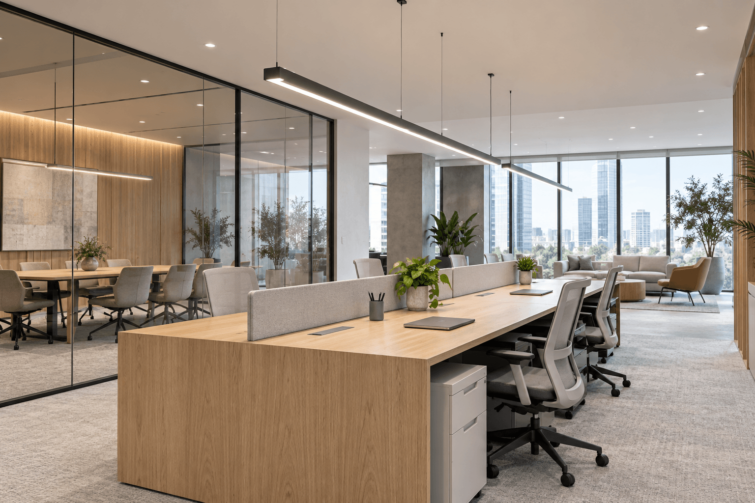
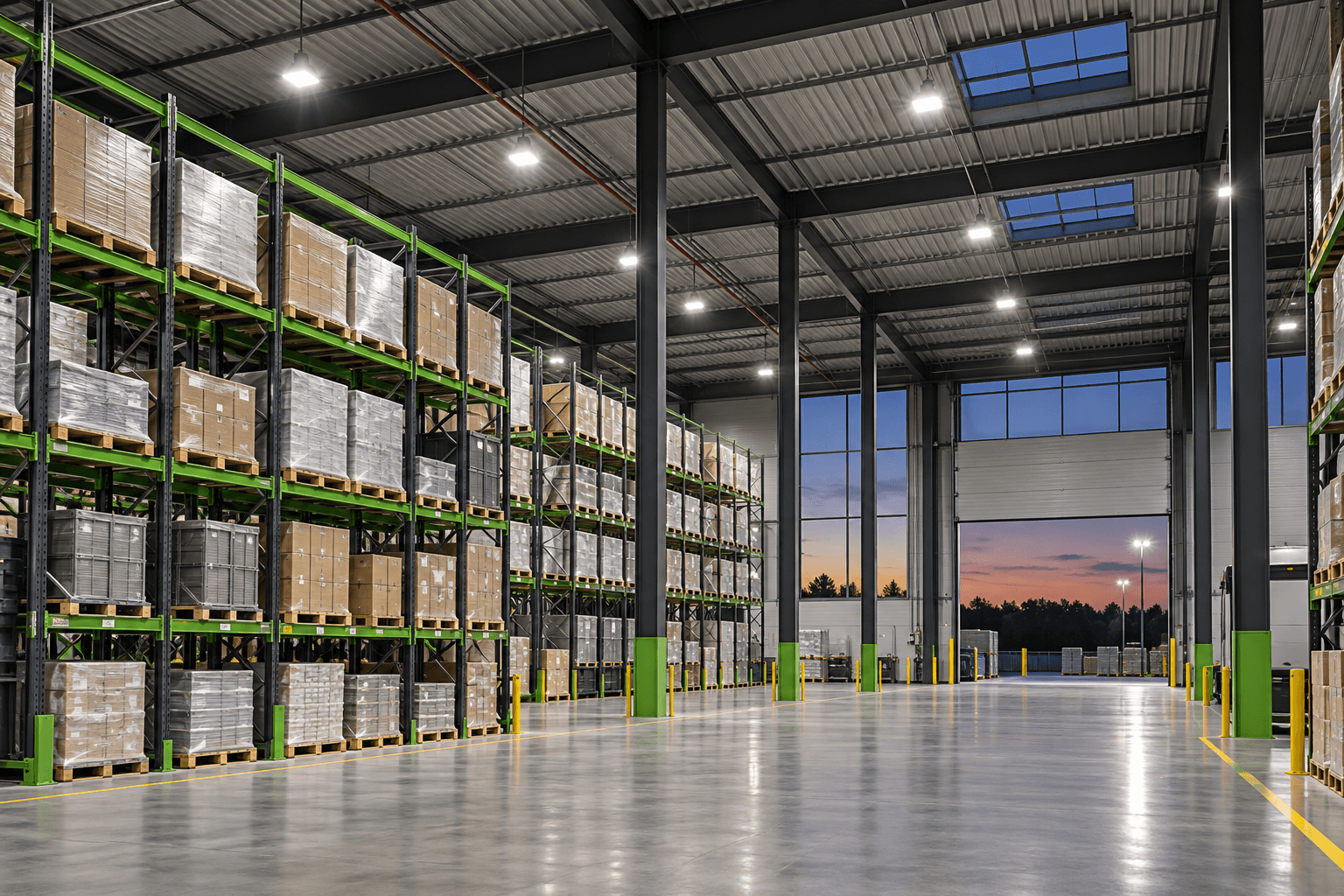
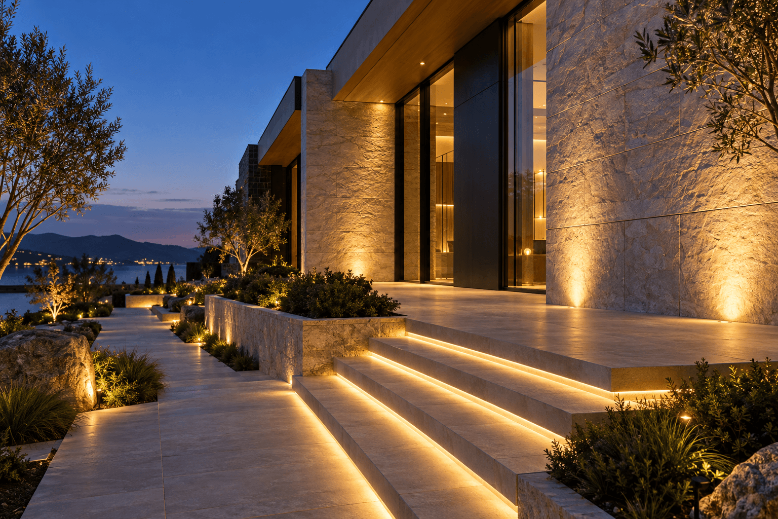
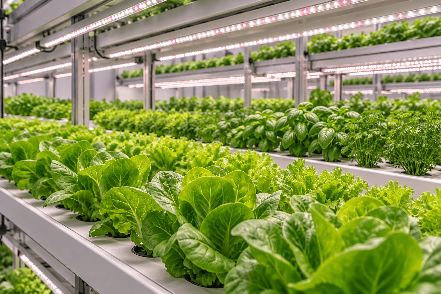
We build LED PCB assemblies and finished lights for commercial, outdoor, architectural, horticulture, automotive, and smart lighting.
 Commercial & indoor lighting
Panel lights, downlights, track lights, linear lights, and tube lights.
- Outdoor & industrial lighting
Street lights, floodlights, and high bay lights.
- Architectural & decorative
Wall washers, RGB/RGBW strips, landscape and facade lighting.
- Horticulture
Full-spectrum LED grow light boards with high-power thermal design.
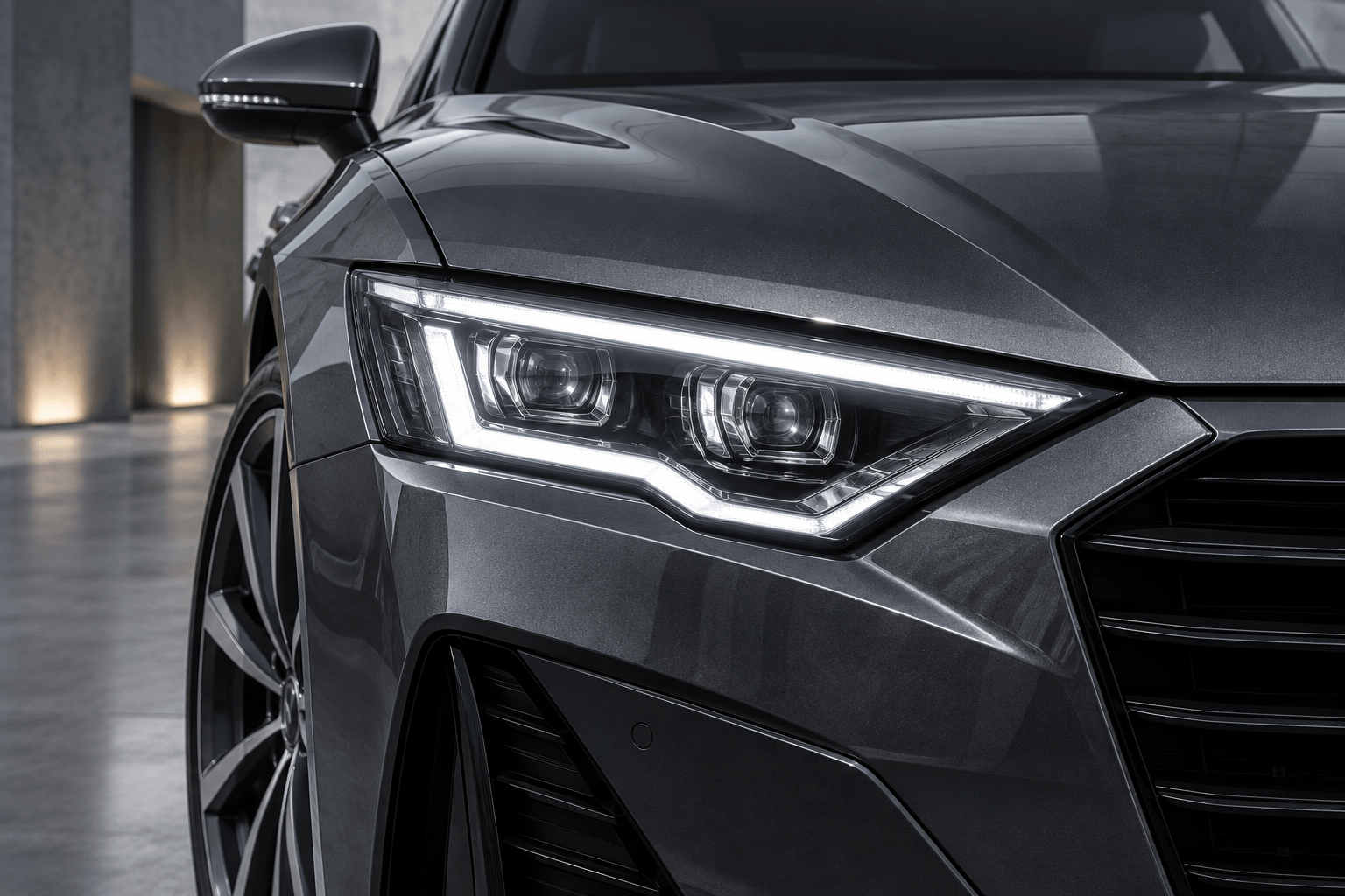
- Automotive lighting
IATF-certified builds for interior, signal, and auxiliary lighting modules.
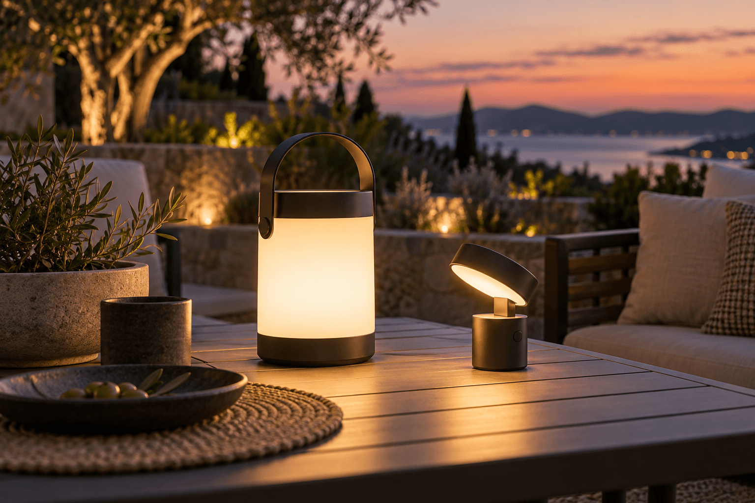
- Smart & portable lighting
Wi-Fi/BLE controlled lights, solar lights, flashlights, and battery-powered lamps.
Common LED project risks, solved upfront
Most LED quality problems—color mismatch, early dimming, and flicker—start before production, so we control them at design, sourcing, and inspection.
“Our last batch had visible color differences between lights.”
Bin lock-down + first article check. We fix the CCT and flux bin on your BOM, verify it at IQC, and never mix bins in one batch without your approval.
“The LEDs got too hot and dimmed after a few months.”
Thermal design + X-ray void control. Our engineers review the heat path from LED to housing, choose the right substrate, and check solder voids under thermal pads by X-ray.
“Our lights started flickering or failing in the field.”
Driver design + dimmer testing + burn-in. Most field failures start at the driver. We design stable constant-current drivers, test with your target dimmer or controller, and burn in every batch to catch early failures before shipment.
Get an accurate LED PCBA quote
If you are starting from an idea
- Application and where the light will be used (indoor, outdoor, vehicle, etc.)
- Size or housing limits, sketch, or reference product
- Target lumens, CCT, CRI, beam angle, and color needs
- Input voltage, power budget, and dimming or control method
- Target quantity, target cost, and required certifications
If you have design files
- BOM with exact MPNs, LED bin codes, and no-substitution flags
- Gerber/ODB++, pick-and-place file, and assembly drawings
- Housing, cable, and optic drawings (STEP/CAD) if assembly is needed
- Firmware, test procedure, and pass/fail criteria
- Labeling, packaging, prototype count, and batch quantity
All files are handled under strict confidentiality. We gladly sign your NDA before file transfer.
LED assembly FAQ
Materials, color consistency, testing, and your next build.
What is the difference between LED PCB fabrication and LED PCB assembly?
LED PCB fabrication makes the bare board—aluminum, copper-core, FR-4, or ceramic—with circuits, solder mask, and surface finish. LED PCB assembly mounts the LEDs, driver ICs, and connectors on that board, then solders, inspects, and tests it. OrinewPCB does both in-house, so one team owns thermal design, board quality, and assembly yield. See LED PCB for bare-board options.
Should I use an aluminum PCB or FR-4 for my LED board?
It depends on power density and the heat path. Low-power indicator or strip boards can work on FR-4 with thermal vias under the LED pads. Mid- to high-power lights—downlights, floodlights, high bays, and grow lights—usually need an aluminum MCPCB, because the metal base moves heat from the LEDs to the housing much faster. Our engineers recommend the right substrate during the free DFM review.
What thermal conductivity (W/m·K) should I specify for an MCPCB?
As a general guide, 1.0–2.0 W/m·K aluminum boards suit most indoor commercial lighting, while high-output floodlights and high bays often need 2.0–3.0 W/m·K or higher. Extreme power densities may call for copper-core or ceramic boards. The right value also depends on dielectric thickness, LED thermal pad size, and housing contact, so we review the full heat path rather than one number. See our Aluminum PCB page for board options.
Can you design an LED product if I only have an idea?
Yes. Share your application, size limits, and target specs such as lumens, CCT, CRI, and input voltage. Our engineers handle LED and driver selection, schematic, PCB layout, thermal design, and prototyping, and you approve each step before production.
Can you meet specific brightness, CCT, and CRI targets?
LED series, CCT and flux bins, LED count, and drive current are selected around your targets. Photometric verification is available on request; agree the test scope when quoting.
Why do LEDs in one batch look different in color, and how do you prevent it?
Common causes are mixed LED bins, LEDs that absorbed moisture before reflow (which can crack the package and shift color), and excess heat during soldering. We use one bin per batch (or a bin combination you approve), bake moisture-sensitive LEDs per their MSL rating before assembly, and tune the reflow profile for each LED board.
Can you source genuine LEDs from brands like Nichia, Osram, Lumileds, Cree LED, or Samsung?
Send your exact LED manufacturer part numbers and bin requirements. Our team reviews sourcing availability with your quote. No substitutions are made without written approval.
What tests do LED assemblies go through?
Every build passes 9 inspection stages: IQC, SPI, online AOI, SMT first article, IPQC, offline AOI, X-ray, QC functional test, and QA pre-shipment audit. Lighting tests include a 100% light-up test, electrical checks, burn-in to your agreed test plan, and photometric tests on request.
How do you prevent LED flicker?
Flicker can result from driver design, dimmer incompatibility, or overheating. Share your controller and operating conditions so the engineering team can review the driver and testing requirements.
What information do you need to quote my LED project?
If you are starting from an idea: application, size limits, target lumens, CCT, CRI, input voltage, dimming method, and quantity. If you have files: Gerber, BOM with exact MPNs and LED bin codes, pick-and-place data, assembly drawings, and test requirements. Missing details are fine—our engineers will help fill the gaps.
What affects the cost of LED PCB assembly?
The main cost drivers are LED and driver parts, board material and size (MCPCB type, thermal conductivity, copper weight), component count, through-hole and cable work, testing scope such as burn-in and photometric tests, and order quantity. Design projects also include one-time engineering work. We provide an itemized quote after reviewing your project.
Is there a minimum order quantity?
No. We build from a single prototype through pilot runs to 5,000+ units, and your dedicated specialist confirms the schedule with your quote.
Have a lighting idea?
Let’s build it.
Send your idea, specs, or design files. A dedicated engineer will reply with DFM feedback, recommendations, and a quote.
[email protected]Share your BOM, Gerber files, LED bin requirements, and lighting targets. Starting from an idea? Tell us your application and quantity. NDA requests are welcome.
