SMT vs Through-Hole PCB Assembly: Choosing and Mixing the Right Process
SMT handles the dense, fast, automated part of the board; THT handles the connectors, power parts, and high-voltage components that need a through-board mechanical anchor. Most boards are mixed. Your real job is not picking one technology for the whole board—it is deciding, component by component and process by process, where each earns its place, and knowing what a mixed build costs you in extra process steps before you commit to it.
Get Your PCB Quote!
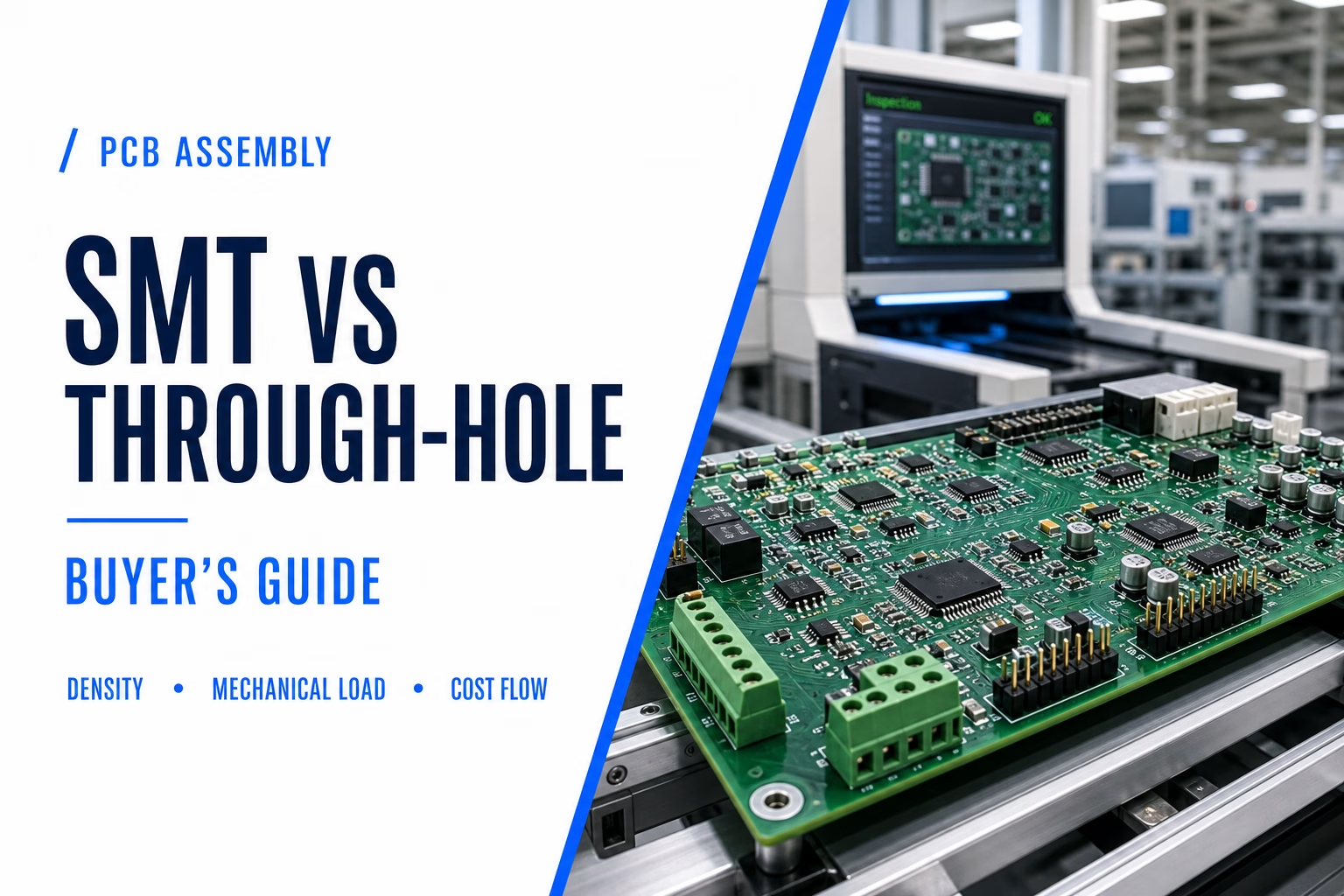
Table of Contents
Table of Contents
SMT is the right default for most of a modern board: it wins on density, electrical performance, and per-unit cost at volume. Through-hole earns its place where mechanical retention, high-voltage isolation, or a THT-only package is involved—and the reality is that most professional boards use both on the same assembly. This guide gives you the decision rules, the cost math, and the mixing rules to choose your assembly strategy before you send files for quote.
Quick Specs
| Attribute | SMT | THT |
| Assembly process | Stencil print → pick-and-place → reflow | Insertion → wave / selective / hand solder |
| Typical board density | High; components on both sides | Lower; each lead needs a drilled hole |
| Mechanical retention | Surface joint only | Through-board anchor (solder fills plated barrel) |
| High-frequency behavior | Short leads, low parasitics | Longer leads + via add inductance/capacitance |
| Volume economics | Per-unit cost drops sharply with volume | Cost stays relatively flat; labor-heavy |
| Rework difficulty | Fine-pitch/BGA need special tools | Usually hand-solderable |
| Best-fit components | Processors, passives, sensors, RF | Connectors, relays, transformers, high-voltage |
Key Takeaways
- SMT is the default process for most of a board; THT is the exception that earns its place for mechanical, high-voltage, or package reasons.
- The cost story is about setup amortization and process count, not a fixed “SMT is cheap” rule: SMT gets cheap at volume, THT stays relatively flat.
- Almost every professional board is mixed—the question is how to mix without paying twice in process steps.
- A mixed build costs more than the sticker sum of its parts: reflow plus wave/selective soldering adds a process step, and every step adds cost and defect opportunity.
- Ask your assembler the right questions about mixed-build setup before quoting, not after.
Where SMT wins by default—and the three cases that overrule it
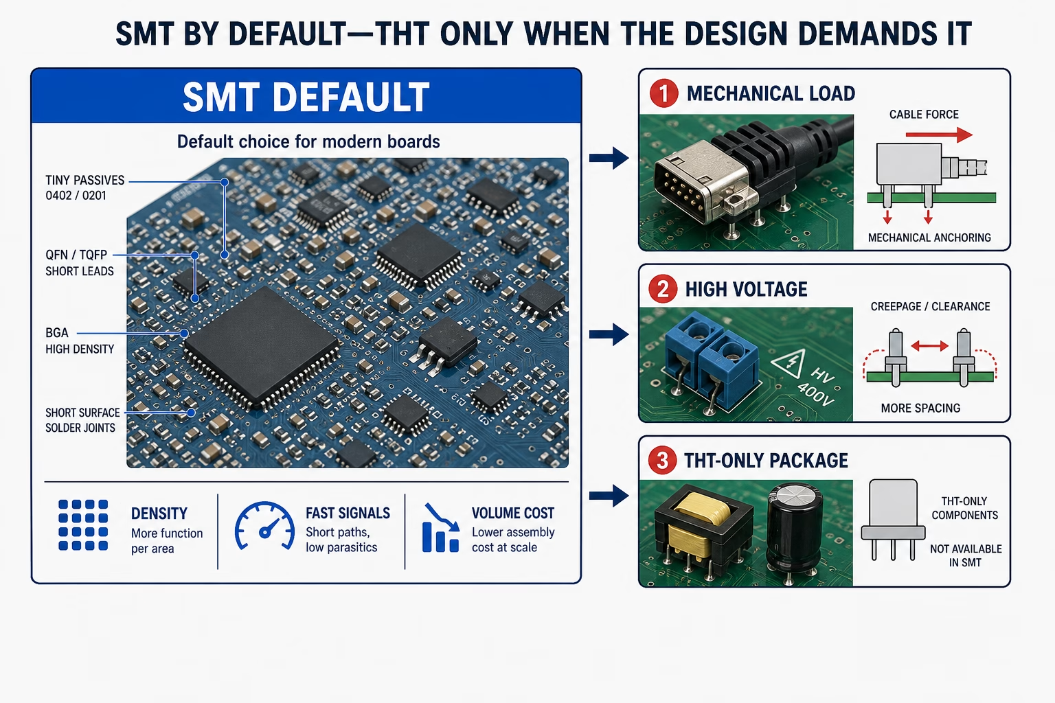
Walk into any modern assembly line and the default is SMT. Solder paste is stencil-printed onto surface pads, a pick-and-place machine positions components by the tens of thousands per hour with micron-level placement accuracy, and a reflow oven forms all the joints in one pass. Component sizes from 0201 down to 01005 are barely visible to the naked eye, which is how a smartphone packs thousands of parts onto a board the size of a playing card.
That default holds until one of three things is true:
- The component must take mechanical abuse. A connector that gets mated and unmated repeatedly, a terminal block that carries cable tension, a relay or large transformer that vibrates—these put loads on the joint that a surface solder joint is not built for. Through-hole leads pass through the board and are soldered inside a plated barrel, so the load is distributed into the board’s full thickness instead of hanging off a surface land.
- The design needs high-voltage isolation. The physical separation between through-hole leads makes creepage and clearance distances easier to achieve. A 2mm pitch SMT connector and a through-hole terminal block with the same rating are not equal when your design has to hold off a few kilovolts.
- The part only exists in a THT package. Bulk capacitors, transformers, connectors, and some power semiconductors are simply not offered in surface-mount form because their physical requirements—bulk capacitance, current, voltage isolation, mechanical retention—do not fit an SMT package.
| Decision factor | SMT | THT | What it means for your build |
| Component density | High; both sides populated | Lower; each lead needs a hole and routing space | SMT is the only path to miniaturized layouts |
| Mechanical load | Fine for light parts; vulnerable to connector/switch forces | Through-board anchoring for connectors, relays, transformers | Plan THT where a user will physically touch or stress the part |
| Electrical path | Short leads, small loops, low parasitics | Longer leads and vias add inductance/capacitance | SMT default for fast digital and RF; verify THT on fast nets |
| Volume economics | Setup amortized; per-unit cost drops fast | Labor/process cost stays relatively flat | Pure-SMT wins at volume; THT wins below the setup crossover |
| Rework | Fine-pitch and bottom-terminated parts need special tools | Hand-solderable, probe-able, replaceable | THT is friendlier for early prototypes and field service |
| Typical best fit | Processors, memory, sensors, passives, RF | Connectors, high-power parts, high-voltage, legacy/serviceable | Most boards need a mix of both rows |
Decision rule: start with SMT on any component that has an SMT package and no mechanical-load reason to do otherwise. Switch to THT only when the component is part of the product’s mechanical structure, needs high-voltage separation, or has no SMT offering.
The cost math: why SMT gets cheap at volume and THT stays flat
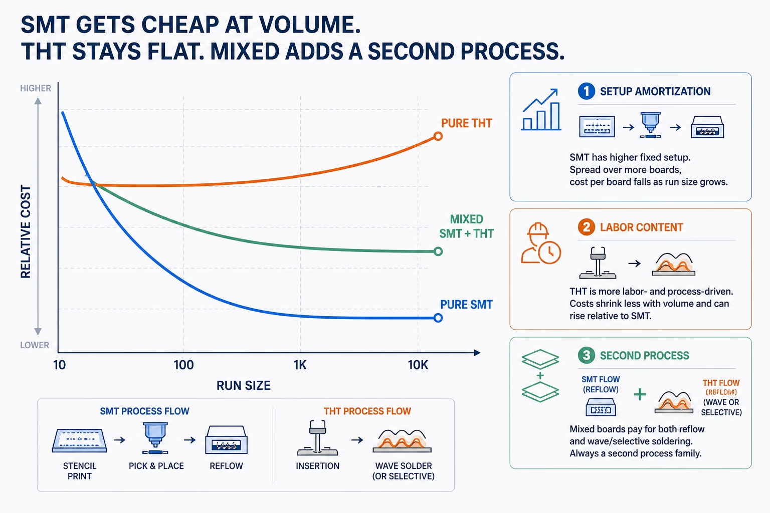
The “SMT is cheaper” claim needs a volume qualifier, because it is really a story about setup amortization and process count.
SMT carries fixed setup costs: the stencil, the pick-and-place program, and the line changeover. Those are paid once, then spread across every board in the run. At 1,000 boards the setup is noise; at 10 boards it dominates. THT has less setup overhead per order but carries labor—hand insertion or machine insertion, then a wave/selective soldering pass—that does not shrink much with volume.
The table below is directional, not a quote—real numbers depend on your BOM, panelization, and your assembler’s rate card. It shows the shape of the cost curve, which is what matters for the decision.
| Run size | Pure SMT (relative) | Pure THT (relative) | Mixed SMT+THT (relative) |
| 10 boards (prototype) | 1.0x | ~0.9x | ~1.3x |
| 100 boards | 1.0x | ~1.1x | ~1.3x |
| 1,000 boards | 1.0x | ~1.5x | ~1.2x |
| 10,000 boards | 1.0x | ~2.0x+ | ~1.2x |
Directional figures modeled from typical US/Asia contract-assembly economics; relative to the pure-SMT cost at each run size, not absolute prices. Treat as a curve shape, not a quote.
Read the pattern: at prototype volume SMT’s setup makes it the expensive option and THT looks fine; by 1,000 boards the SMT advantage is clear and THT’s labor drag grows; mixed sits above pure SMT at every volume because it pays for two process families.
A mixed board goes through reflow AND then wave or selective soldering (plus a possible adhesive pass for bottom-side SMT). That is a second main process with its own setup, its own stencils/pallets, and its own defect surface. If an assembler quotes a mixed board as two independent line items, ask what the process flow actually is—the combined cost and lead time are driven by the flow, not the sum of the part counts.
The mixed-technology board: how production actually flows
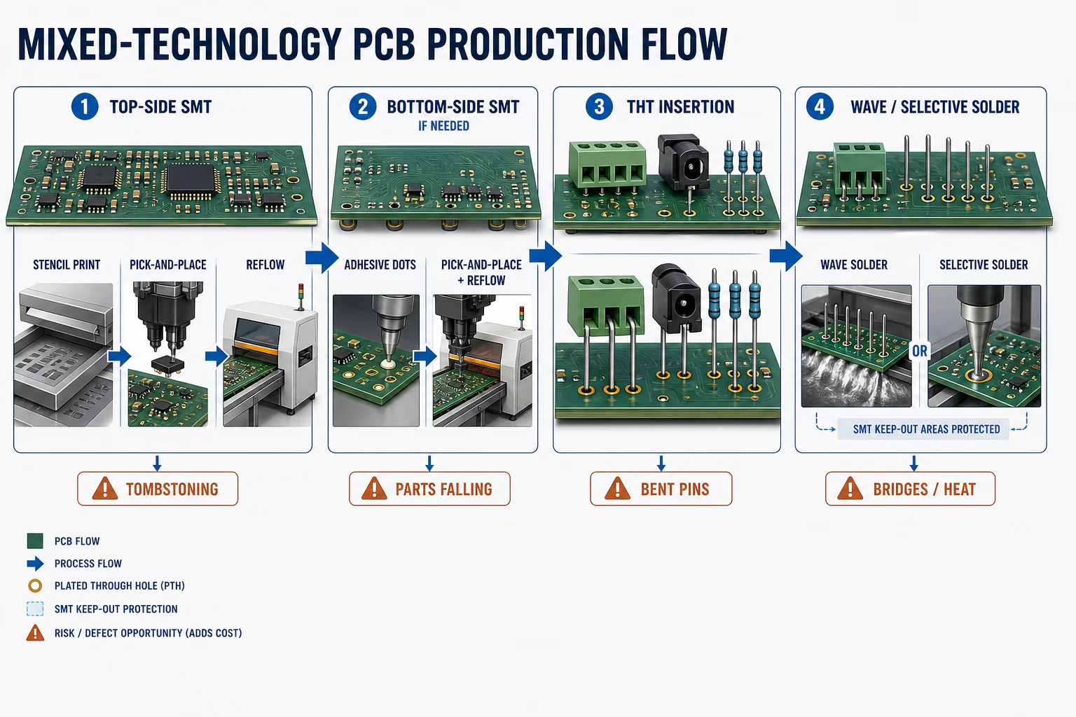
Most professional designs are mixed whether the engineer thinks of them that way or not—an industrial board is often 95% SMT with a handful of through-hole connectors and terminal blocks that take abuse in the field. The production flow is where mixing gets real.
| Step | What happens | Most common failure |
| 1. Top-side SMT | Solder paste printed, components placed, reflow | Tombstoning / solder balling on fine-pitch parts |
| 2. Bottom-side SMT (if any) | Adhesive applied, components placed, second reflow | Parts falling off during the wave step if adhesive is skipped or weak |
| 3. THT insertion | Leads inserted through plated holes | Bent pins, skewed connectors, components not fully seated |
| 4. Wave or selective soldering | Molten solder wets the through-hole joints | Solder bridges; thermal damage to nearby SMT parts; shadowing behind tall parts |
Two things matter in this flow. First, every additional step is a place where cost and defects enter—an assembler who routes your board through reflow plus wave plus hand-touch-up is giving you three defect surfaces for the price of one design. Second, the wave-soldering step is the one that most often damages your own design decisions: bottom-side SMT parts near the wave can overheat or shadow, and tall THT parts can block solder from reaching joints behind them.
Six design rules that keep a mixed board cheap (and what each violation costs)

The difference between a mixed board that assembles cleanly and one that eats margin in rework is usually decided in layout, not on the line. These six rules are the ones that show up repeatedly in DFM reviews:
| Design rule | What it actually is | Cost of violating it |
| 1. Put all SMT on the top side if possible | Avoids the adhesive + second reflow step for bottom-side parts | One extra process step and its defect rate on every board |
| 2. Keep wave-soldered THT parts away from SMT parts that can’t take wave temperature | Thermal profile is global, not per-component | Thermal damage to SMT joints near the wave |
| 3. Orient THT parts so tall ones don’t shadow short ones | Solder needs line of sight in wave soldering | Dry joints / open joints behind tall components |
| 4. Give the wave process enough edge clearance and pallet clearance | Wave solderers use pallets/masks to protect areas | Masking labor, or solder wicking where you don’t want it |
| 5. Check THT hole-to-pad ratios against your assembler’s limits | Too-tight holes break insertion; too-loose leak solder | Insertion stops, or wicking up the lead instead of filling the barrel |
| 6. Confirm the assembly panel includes process edges for both processes | Reflow and wave have different edge/tooling needs | Extra panelization rework or hand-held processing |
Point to remember: the goal of mixed-board layout is to keep the process flow to its minimum—ideally one reflow pass and one wave/selective pass, with nothing forcing a third operation. Every rule above exists to protect that minimum.
Mechanical and electrical reality checks
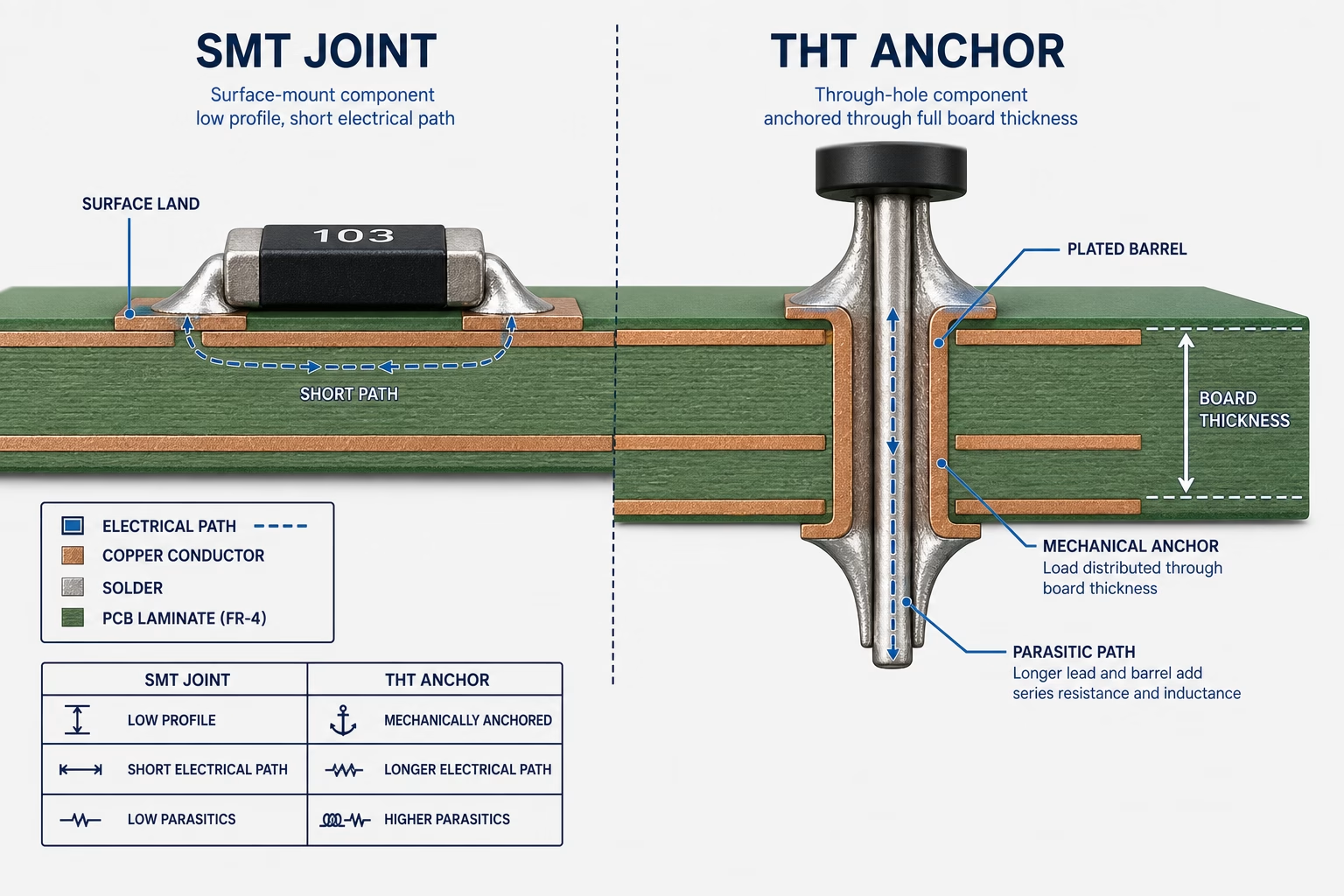
The mechanical story is the one most buyers get right: through-hole joints are stronger because the solder fills a plated barrel through the board’s full thickness, anchoring the lead into the laminate. That is why USB connectors, terminal blocks, relays, large inductors, and power semiconductors stay on THT—the solder joint is part of the product’s mechanical structure, not just its electrical path. SMT joints bond to a surface land only, which is fine for light parts and loads parallel to the board, and genuinely wrong for a connector that gets pulled, pushed, or mated thousands of times.
The caveat that almost nobody says: THT retention does not make an underspecified connector indestructible. A connector chosen by pin count and pitch alone—with the electrical footprint fitting but no mounting support for the cable force—still cracks solder or lifts pads after repeated use. The through-hole joint shares the load; it does not replace proper mechanical design. A high-force connector needs THT pins for the electrical path, dedicated anchor posts for the mechanical load, and ideally an enclosure feature that carries cable tension away from the joints.
On the electrical side, SMT is the safer default for high-speed and RF because the connection is short and the current loop is small—that advantage comes from geometry, not from the label. THT adds lead length and a plated barrel through the stackup, both of which contribute parasitic inductance and capacitance. The effect shows up not at the clock frequency but at the edge rate: a digital signal with a sub-nanosecond rise time carries significant high-frequency energy, and a long THT lead can act as a transmission-line discontinuity rather than a harmless wire. A practical line: if a net is fast digital or RF, route it on SMT and verify; a carefully constrained THT connection can work at lower speeds, but it needs the parasitics accounted for, not ignored.
One honest caveat on the numbers: “THT is mechanically stronger” is industry consensus, but how much stronger has no single published figure—manufacturers test retention and vibration by different methods and report different numbers. Treat any precise strength claim from a single source as that source’s test result, not a universal constant.
Are through-hole components obsolete?
No—and the question itself assumes a binary that does not exist in production. Through-hole is not competing with SMT for the same sockets; it is the only option in the categories where it is used:
- Connectors and terminals that must survive repeated mating and cable tension
- Power components—transformers, large capacitors, relays, power semiconductors with heatsinks—where mass and thermal path need a through-board anchor
- High-voltage parts where physical lead separation is what achieves the required creepage and clearance
- Field-serviceable items where a technician needs to replace a part with basic tools
The real trend is not “THT is dying” but “the mix is shifting.” New designs put more of the board on SMT because density and automation economics demand it, while THT concentrates into the sockets where it is structurally required. Almost every professional board you will see this year is mixed. What changed is that “all-THT” boards are now rare outside low-cost, low-density, or educational products—and THT as a percentage of the component count has shrunk while its absolute presence in connectors and power stages has not gone away.
Point to remember: treat “through-hole is obsolete” the way you treat “mechanical parts are obsolete”—the technology that holds the product together is not going anywhere, it just stopped being the headline.
The nine-question RFQ checklist for your assembler
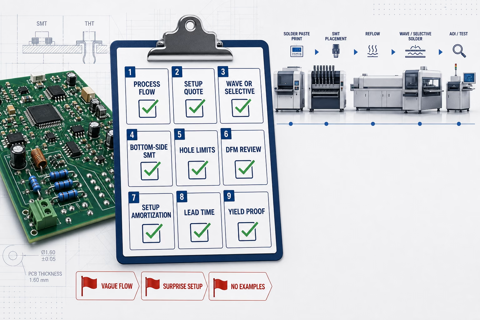
The fastest way to learn whether your assembler actually runs mixed boards well is to ask directly. These nine questions are the ones that separate a real mixed-build process from a line that treats THT as an afterthought:
| # | Ask this | Why it matters | Red flag |
| 1 | Is the board pure SMT, pure THT, or mixed—and what is your process flow for each? | You need the real flow, not a line-item sum | No clear flow; vague “we handle it” |
| 2 | How is mixed-build setup quoted—per process step or bundled? | Setup is where mixed boards hide cost | Per-step surprises after quote |
| 3 | Do you use wave or selective soldering for THT, and why? | Selective soldering protects nearby SMT; wave is cheaper | Only one option offered, no tradeoff explained |
| 4 | How do you protect bottom-side SMT parts during the wave step? | Adhesive + masking is a real cost/defect surface | No answer, or “we just don’t do bottom-side SMT” |
| 5 | What are your THT hole-to-pad and insertion limits? | Design must meet the process, not the other way around | Limits disclosed only after you send files |
| 6 | Do you review mixed-board layout for shadowing and wave clearance in DFM? | Layout decides yield on mixed boards | DFM is optional or an upsell |
| 7 | What is your stencil + programming setup cost, and how does it amortize? | Setup amortization is the whole SMT volume story | Setup quoted as a fixed high fee with no amortization |
| 8 | What is the realistic lead time for a mixed build vs pure SMT? | Process count adds time, not just money | Same lead time promised for both |
| 9 | Can I see a mixed-build example of yours—BOM, layout, and yield data? | Proof beats promises | No examples, no yield data |
Decision rule: if an assembler cannot answer questions 2, 4, and 9 with specifics, their mixed-process capability is unproven—and that is exactly the capability your board depends on.
When to pick one over the other (self-diagnostic table)
If your product is not obviously one process or the other, run it through this table. Find your row, read across, and you have a defensible starting answer—then confirm with your assembler before layout locks in.
| Your product reality | Recommended strategy |
| High-density consumer device, no high-force connectors | Pure SMT; THT only for the battery/charging connector |
| Industrial board with connectors + terminal blocks on a mostly SMT design | Mixed: SMT for logic/power stages, THT for connectors and power terminals |
| High-voltage power supply or isolation stage | THT where creepage/clearance matter; SMT for control logic |
| Vibration-heavy product (automotive, machinery) | THT for connectors/transformers; SMT for logic with conformal coating where needed |
| Prototype / early iteration, frequent changes | Lean THT for serviceable parts or hand-solder-friendly design; SMT if the team has rework tools |
| Extreme cost sensitivity at high volume | Pure SMT if at all possible; audit every THT socket for an SMT alternative |
And the reverse—the two cases where you should actively avoid each process:
- Avoid SMT when a heavy or user-stressed component has no mechanical anchor beyond its solder joints. A 10g connector held by surface joints alone will fail in the field.
- Avoid THT when the board is density-constrained or high-frequency, and the THT part is a convenience choice rather than a structural requirement. You are paying in board area and parasitics for something SMT does better.
As the assembler, we would rather you mix deliberately than default to either extreme—a board designed around its real process flow quotes faster, builds cleaner, and fails less.
Conclusion
The answer to “SMT or through-hole?” is that most boards need both, and the useful question is where each earns its place. SMT is the default: denser, faster, cheaper at volume, and better electrically. Through-hole is the exception that earns its place for mechanical retention, high-voltage isolation, and THT-only parts. The cost math is about setup amortization and process count—SMT gets cheap as volume grows, THT stays flat, and mixed boards pay for a second process family. Layout decides whether that second process costs you once or every run. OrinewPCB runs reflow, wave, and selective soldering on the same line and reviews mixed-board DFM before quoting—if you want your BOM checked against these rules, send it over and we will tell you where the process flow will cost you.
FAQ
Are through-hole components obsolete?
No. Through-hole remains the only package option for connectors, transformers, high-voltage parts, and other components that need a through-board mechanical anchor. What changed is the mix: new designs put more of the board on SMT while THT concentrates into the sockets where it is structurally required.
What are the disadvantages of through-hole soldering?
THT uses more board area, adds a wave or selective soldering process step on mixed boards, and has higher labor content that does not shrink much with volume. It also adds parasitic inductance and capacitance that must be accounted for on high-speed nets.
When to use SMD vs through-hole?
Use SMT as the default for density, high-frequency, and volume economics. Use through-hole when a component must survive mechanical abuse, needs high-voltage creepage/clearance, or only exists in a THT package. Most professional boards use both.
Is mixed SMT/THT assembly more expensive?
Yes, relative to pure SMT at the same volume—a mixed board pays for two process families (reflow plus wave or selective soldering), each with its own setup and defect surface. The premium is usually modest at volume but can be significant for small runs, so get the process flow quoted, not just a line-item sum.
Can SMT and THT components be on the same board?
Yes—this is the standard case in production. SMT parts are reflowed first, THT parts are then inserted and wave or selectively soldered. The design rules that keep this cheap are putting SMT on one side where possible and keeping wave-sensitive parts clear of the wave zone.
About This Guide
This guide is written from the assembler’s side of the table: OrinewPCB runs SMT reflow, wave soldering, and selective soldering, and the process-flow and DFM observations here come from running mixed boards in production. Cost figures in the run-size table are directional models of typical contract-assembly economics, not quotes—treat them as a curve shape and confirm with a live quote. The mechanical-strength comparison is industry consensus; exact retention numbers vary by manufacturer test method, and we say so rather than presenting a single number as universal. Process descriptions follow IPC-A-610/J-STD-001 assembly practices.
References & sources
- SMT vs Through-Hole Assembly: Technical Comparison — EMS Technologies (process flow, cost drivers, mixed-build steps).
- SMT vs through-hole components: an engineering guide — OrinewPCB (mechanical/electrical/thermal depth; sister article).
- IPC-A-610J — Acceptance Criteria for Electronic Assemblies (joint quality, rework criteria).
- IPC J-STD-001J — Requirements for Soldered Electrical and Electronic Assemblies (soldering process requirements).
Related articles
- SMT vs through-hole components: an engineering guide—the component-level mechanical and electrical depth behind this article’s process view.
- What is SMT production line?—how the SMT line is configured and sequenced.
- Wave soldering temperature profile—what the wave step actually exposes your board to.
- What is solder paste?—the paste printing step that starts every SMT build.

Get Quote Free