PCB Assembly Guide: SMT, THT, Prototypes, and Volume Selection
Choose the right PCB assembly process and production volume. Compare SMT, THT, prototype, low-volume, pilot, and high-volume manufacturing options.
Get Your PCB Quote!
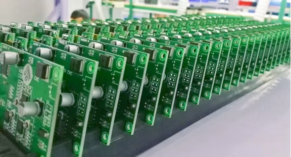
Table of Contents
- ภาพรวมกระบวนการประกอบแผงวงจรพิมพ์ (PCB) และการเลือกขนาด
- การประกอบ PCB คืออะไร?
- การประกอบแบบ SMT: มาตรฐานสำหรับอุปกรณ์อิเล็กทรอนิกส์ที่มีความหนาแน่นสูง
- การประกอบแผงวงจรพิมพ์ (PCB) ของ THT: เมื่อความแข็งแรงเชิงกลเป็นสิ่งสำคัญ
- การประกอบแบบ SMT และ THT ผสมกัน
- การประกอบต้นแบบแผงวงจรพิมพ์ (PCB): ปรับให้เหมาะสมเพื่อการเรียนรู้
- การประกอบแผงวงจรพิมพ์ (PCB) ปริมาณน้อยและหลากหลายสูง
- การประกอบแผงวงจรพิมพ์ปริมาณมาก: ปรับให้เหมาะสมเพื่อความสม่ำเสมอ
- เส้นทางการตัดสินใจเลือกปริมาณที่ใช้งานได้จริง
- การทดสอบครอบคลุมทั้งต้นแบบ ปริมาณการผลิตน้อย และปริมาณการผลิตมาก
- ปัจจัยที่ส่งผลต่อต้นทุนและระยะเวลาดำเนินการตามแต่ละขั้นตอนของโครงการ
- วิธีการเตรียมเอกสารขอใบเสนอราคา (RFQ) สำหรับการประกอบแผงวงจรพิมพ์ (PCB)
- การเลือกพันธมิตรด้านการประกอบแผงวงจรพิมพ์ (PCB)
- คำถามที่พบบ่อย
- ที่มาและอ่านต่อ
- สรุป
Table of Contents
- ภาพรวมกระบวนการประกอบแผงวงจรพิมพ์ (PCB) และการเลือกขนาด
- การประกอบ PCB คืออะไร?
- การประกอบแบบ SMT: มาตรฐานสำหรับอุปกรณ์อิเล็กทรอนิกส์ที่มีความหนาแน่นสูง
- การประกอบแผงวงจรพิมพ์ (PCB) ของ THT: เมื่อความแข็งแรงเชิงกลเป็นสิ่งสำคัญ
- การประกอบแบบ SMT และ THT ผสมกัน
- การประกอบต้นแบบแผงวงจรพิมพ์ (PCB): ปรับให้เหมาะสมเพื่อการเรียนรู้
- การประกอบแผงวงจรพิมพ์ (PCB) ปริมาณน้อยและหลากหลายสูง
- การประกอบแผงวงจรพิมพ์ปริมาณมาก: ปรับให้เหมาะสมเพื่อความสม่ำเสมอ
- เส้นทางการตัดสินใจเลือกปริมาณที่ใช้งานได้จริง
- การทดสอบครอบคลุมทั้งต้นแบบ ปริมาณการผลิตน้อย และปริมาณการผลิตมาก
- ปัจจัยที่ส่งผลต่อต้นทุนและระยะเวลาดำเนินการตามแต่ละขั้นตอนของโครงการ
- วิธีการเตรียมเอกสารขอใบเสนอราคา (RFQ) สำหรับการประกอบแผงวงจรพิมพ์ (PCB)
- การเลือกพันธมิตรด้านการประกอบแผงวงจรพิมพ์ (PCB)
- คำถามที่พบบ่อย
- ที่มาและอ่านต่อ
- สรุป
Choosing a PCB assembly method is not only a question of whether a board uses SMT or THT. The right process also depends on the product stage, component mix, test requirements, expected quantity, design stability, and how much production data you need.
A prototype may need flexible sourcing and fast engineering feedback. A low-volume product may need high-mix changeovers and repeatable test coverage. A high-volume product may justify dedicated fixtures, optimized panelization, automated material handling, and tighter process monitoring.
This guide explains how to choose between SMT, THT, and mixed-technology assembly, then maps those processes to prototypes, pilot builds, low-volume production, and high-volume manufacturing.
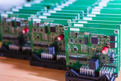
PCB assembly process and volume selection at a glance
| Project situation | Usually prioritize | Main risk to control |
| Prototype or design validation | Flexible SMT/THT assembly, quick DFM feedback, accessible test points, flying probe or flexible functional test | Spending on production tooling before the design is stable |
| Pilot or first article | Controlled BOM and firmware, stencil and fixture validation, profile confirmation, AOI, and functional test | Treating the pilot as a small production order instead of a process qualification step |
| Low-volume, high-mix production | Fast changeovers, traceable materials, modular test, flexible sourcing, and repeatable inspection | Setup time, component shortages, and revision confusion across multiple SKUs |
| High-volume production | Stable BOM, optimized panel, automated placement, fixture-based test, process data, and supply continuity | Scaling a design or process that has not been proven at production conditions |
| Mixed SMT/THT board | Reflow plus selective, wave, press-fit, or manual operations selected by the mechanical load | Thermal exposure, shadowing, solder access, and extra handling |
The quantity labels above are planning categories, not universal industry thresholds. A supplier may define low volume or high volume differently depending on board size, component count, number of variants, and production schedule.
What is PCB assembly?
PCB assembly is the process of mounting electronic components onto a bare printed circuit board and creating the soldered and mechanical connections required for the product. A complete service may also include component sourcing, programming, inspection, electrical testing, coating, calibration, packaging, and box build.
The bare PCB is the fabricated substrate. The populated PCBA is the assembled board. A quote should state whether the supplier is responsible for PCB fabrication, component procurement, assembly only, or the full turnkey flow.
The core PCB assembly steps
Most modern builds combine the following operations:
1. Review Gerbers or ODB++, BOM, pick-and-place data, assembly drawings, and revision information.
2. Perform DFM/DFA checks for panelization, stencil, component spacing, polarity, thermal balance, and test access.
3. Source and inspect components, including approved alternates and moisture-sensitive devices.
4. Print solder paste and measure the deposit with SPI when the process requires it.
5. Place SMT components and solder them in a controlled reflow profile.
6. Insert and solder THT parts using selective soldering, wave soldering, press-fit, or manual operations.
7. Inspect visible and hidden joints using AOI, 3D AOI, or X-ray as appropriate.
8. Run ICT, flying probe, functional test, programming, calibration, or environmental testing according to the product requirements.
9. Release the boards with inspection, test, traceability, and nonconformance records.
The correct process is the one that provides the required assembly quality and evidence at the expected quantity. More automation is not automatically better if the design data, inspection program, or test limits are uncontrolled.
SMT assembly: the default for dense electronics
Surface-mount technology places components directly onto PCB pads. SMT supports small packages, dense routing, components on both sides, and automated high-mix production. It is widely used for processors, memory, sensors, RF devices, power-management circuits, connectors, and passive components.
SMT process stages
Solder-paste printing
A stencil transfers solder paste onto the pads. Stencil thickness, aperture design, paste type, board support, alignment, and print parameters affect the deposited volume.
Fine-pitch or thermally unbalanced designs need more than a generic stencil. The DFM review should consider aperture reduction, pad geometry, large thermal pads, fiducials, and the relationship between paste volume and the reflow profile.
Solder-paste inspection
SPI measures the paste before placement. It can identify insufficient, excessive, shifted, or bridged deposits early in the process. This is valuable for prototypes and production because it separates a printing problem from a placement or soldering problem.
SPI does not replace AOI. SPI checks the paste deposit. AOI checks the populated board after placement and soldering.
Pick-and-place
Pick-and-place equipment uses feeders, nozzles, machine vision, fiducials, and placement data to install components. The placement program should be tied to a controlled BOM and assembly revision.
Common SMT risks include incorrect feeder loading, polarity errors, wrong rotation, missing parts, tombstoning, bridging, component shift, board warpage, and moisture-related package damage. A machine can repeat a wrong program accurately, so program verification and first-article review matter.
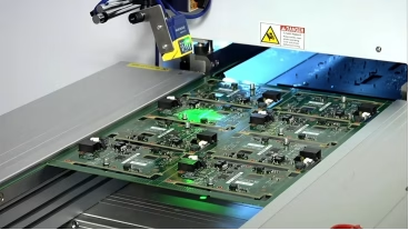
Reflow soldering
The reflow profile must match the solder alloy, component limits, board thickness, copper distribution, and assembly side. A profile copied from another product may not heat a heavy-copper or thermally unbalanced board in the same way.
For a new design, request profile verification and define the acceptable process record. The goal is not simply to prove that solder melted. It is to produce consistent joints without exceeding component or board limits.
When SMT is the right choice
Prioritize SMT when the product needs:
- High component density or small board size
- Automated placement and repeatable production
- Double-sided assembly
- High pin-count or fine-pitch devices
- Rapid changeover across related products
- A path from prototype to repeat production without redesigning the assembly method
For a prototype, SMT does not always mean a full high-speed line. Depending on quantity and package mix, the build may use automated placement, a smaller flexible line, or controlled manual placement for selected parts. The supplier should explain the process and inspection coverage rather than using “SMT” as a complete quality description.
THT PCB assembly: when mechanical strength matters
Through-hole technology inserts component leads through drilled PCB holes and solders them on the opposite side. THT uses more board area than SMT, but it can provide stronger mechanical retention and easier access for some leaded components.
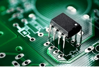
THT is common for:
- Board-to-board and wire-to-board connectors
- Transformers and inductors
- Relays and switches
- Large capacitors
- Components subject to insertion, vibration, or cable loads
- Parts whose available package does not suit SMT assembly
THT process options
Manual insertion and soldering
Manual operations are flexible for prototypes, unusual parts, engineering changes, and small quantities. They need controlled work instructions, operator training, inspection, and a clear rework process.
Wave soldering
Wave soldering can process a suitable group of through-hole joints efficiently. The board layout, component orientation, pallet, solder direction, keep-outs, and nearby SMT parts must be reviewed before choosing it.
Selective soldering
Selective soldering applies solder to defined through-hole locations. It is useful on mixed-technology boards where a full wave process would expose sensitive SMT components or unsuitable areas to unnecessary heat.
Press-fit
Press-fit parts use controlled interference between the contact and the plated hole. The finished hole size, insertion force, connector specification, PCB construction, and inspection method must be defined. Press-fit is not a universal substitute for THT soldering.
When THT is the right choice
Choose THT when the component experiences a mechanical load that the solder joint and SMT pad are not designed to carry alone. The mechanical path should include the connector, lead, pad or barrel, board support, bracket, and enclosure. If the component is repeatedly plugged, pulled, or vibrated, the PCB designer and assembly engineer should review the load together.
Mixed SMT and THT assembly
Many real products use both technologies. SMT handles dense logic and passive components, while THT handles connectors, power parts, relays, or mechanically loaded components.
| Assembly method | Best fit | Design and production considerations |
| Pure SMT | Boards with surface-mount components on one or both sides | Stencil, placement, reflow, and AOI/SPI coverage are central |
| SMT plus selective solder | Dense board with a defined group of THT joints | Nozzle access, pallet, thermal profile, and solder keep-outs matter |
| SMT plus wave solder | Board with a suitable THT population and wave direction | Component shadowing, solder bridges, and bottom-side restrictions need review |
| SMT plus manual THT | Prototype, low volume, unusual parts, or late engineering changes | Work instructions and operator-dependent variation need control |
| SMT plus press-fit | Approved connectors or contacts requiring a solderless mechanical connection | Finished-hole tolerances and insertion-force validation are essential |
Mixed technology can reduce redesign risk, but it adds process steps. The quote should identify the assembly sequence and which inspection method covers each component group.
PCB prototype assembly: optimize for learning
A prototype is not only a smaller production run. Its purpose is to answer questions about the design, performance, manufacturability, and user experience.
What to prioritize in a prototype
- Fast DFM/DFA feedback before committing to a production stencil or fixture
- Clear BOM and revision control
- Components that reflect the intended production design
- Accessible test points and a usable functional-test procedure
- Flexible sourcing and documented alternates
- Inspection that can catch placement, polarity, solder, and hidden-joint problems
- A record of every change made during the build
For a simple board with large packages, controlled manual assembly may be reasonable. For a dense BGA, QFN, fine-pitch, or double-sided design, prototype assembly should use a process that represents the expected production process closely enough to reveal real manufacturing risks.
Prototype quantity does not define prototype quality
One board assembled by hand can answer a mechanical-fit question. It may not answer whether a stencil, reflow profile, AOI program, or fixture will work across a production panel. Conversely, a small automated build can be useful when solder-paste volume, component placement, and repeatability are the key questions.
The build method should follow the question you need to answer.
PCBAndAssembly lists prototype PCB assembly support and no minimum order quantity in its service information. Confirm the exact package, component sourcing, testing, and turnaround for your design rather than assuming every prototype receives the same process.
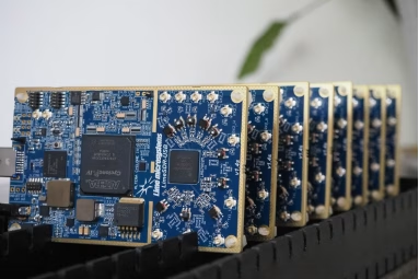
Low-volume and high-mix PCB assembly
Low-volume production is often more difficult than it looks because the factory may build multiple variants, changeover frequently, and source parts in smaller quantities. The challenge is not only machine speed. It is maintaining control when the product mix changes.
What matters in low-volume production
- Fast and accurate changeovers
- Clear variant and revision control
- Flexible component sourcing and approved alternates
- Modular fixtures or flying-probe access
- Repeatable setup verification
- Good material labeling and kitting
- First-article checks when a new variant is released
- A test method that does not create disproportionate fixture cost
A low-volume, high-mix supplier should explain how it prevents feeder, BOM, and program confusion between products. Ask whether each work order has a controlled kit, assembly program, test program, and release record.
When low volume is the right production model
Use low-volume assembly when demand is uncertain, products are customized, the product has many variants, or the design is still changing. It can also suit industrial, scientific, medical, and replacement products where annual demand is limited but quality and traceability are important.
Do not force a high-volume process too early. A dedicated ICT fixture, special pallet, or large component buy may not be justified until the design and demand are stable.
High-volume PCB assembly: optimize for repeatability
High-volume assembly usually makes more investment in fixtures, panelization, material planning, automated placement, test throughput, and process data. The objective is not merely a lower nominal unit price. It is stable output over repeated work orders.
What high-volume production requires
- A stable, revision-controlled BOM and approved vendor list
- Component lifecycle and allocation monitoring
- Production-capable panelization
- Validated stencil, reflow, and soldering processes
- High-throughput inspection and test
- Fixture-based ICT or functional test when justified
- Preventive maintenance and recipe control
- Traceability from material lots to assemblies
- A defined engineering-change and deviation process
- Capacity planning for the expected build schedule
The production ramp should confirm that the process is capable at the real board size, panel format, component mix, and takt requirement. A successful prototype does not prove that a high-volume line will achieve the same result without process work.
When high volume is the right production model
Choose high-volume assembly when demand is repeatable, the design is stable, component supply is planned, and the cost of fixtures and process optimization can be amortized across the build. If the product changes every month, the flexibility of a low-volume line may be more valuable than the theoretical speed of a high-volume line.
Special case: flexible and rigid-flex assemblies
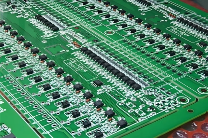
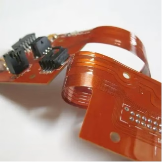
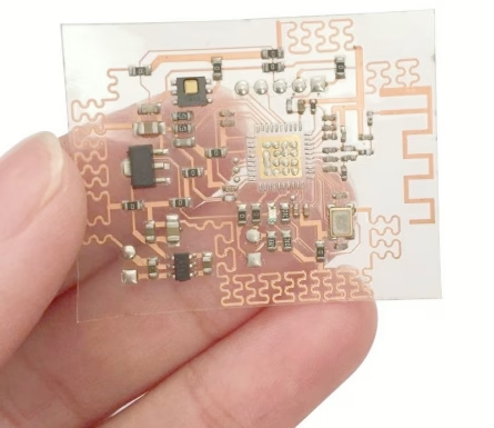
Flexible and rigid-flex boards can change the volume decision because they may need different handling, stiffeners, carriers, bend-area protection, and assembly support. Do not assume that a flexible board can use the same panel, fixture, or reflow support as a rigid FR-4 board. Confirm the assembly method and quantity economics with the supplier before releasing the build.
A practical volume-selection decision path
Use this sequence before choosing a supplier or process:
1. Is the design still changing? If yes, start with prototype or pilot controls and avoid unnecessary dedicated tooling.
2. Does the board contain dense SMT, fine-pitch, BGA, QFN, or double-sided placement? If yes, plan for automated SMT, SPI/AOI, and any required X-ray coverage.
3. Does a component carry mechanical load or require a connector with high insertion force? If yes, review THT, press-fit, brackets, and board support.
4. Are there multiple variants or frequent engineering changes? If yes, prioritize low-volume/high-mix controls, quick changeovers, and version management.
5. Is demand stable and repeated? If yes, evaluate panelization, dedicated fixtures, automated test, and component purchasing strategy.
6. What evidence must ship with the board? Define inspection reports, electrical-test data, material traceability, serial numbers, and certificates before quotation.
This process prevents a common mistake: selecting a production volume first and then trying to force the design and test plan into it.
Testing across prototypes, low volume, and high volume
The test method should scale with product risk and quantity.
| Stage | Practical test approach | Why it fits |
| Prototype | Visual inspection, AOI where useful, flying probe, and functional test | Flexible while the design and test points are still changing |
| Pilot | SPI/AOI, X-ray for defined hidden joints, validated functional test, and first-article records | Confirms the design and process before repeat production |
| Low volume | AOI, flying probe or modular fixture, functional test, and lot traceability | Avoids over-investing in fixed tooling while retaining evidence |
| High volume | Automated inspection, fixture-based ICT/FCT where justified, serial traceability, and process monitoring | Supports throughput and repeatability across many units |
AOI does not replace functional testing. Functional testing does not replace solder-joint inspection. X-ray is not required for every board, but it can be important for selected hidden joints. Define what each test covers and what happens when a board fails.
The assembly testing service should be selected around the product risk and the required evidence, not only around the equipment list.
Cost and lead-time drivers by project stage
Avoid comparing prototype, low-volume, and high-volume prices by unit cost alone. The cost structure changes with the stage.
Prototype cost drivers
- Engineering review and file preparation
- Stencil or other setup costs
- Small-quantity component purchasing
- Manual operations and rework
- Flexible testing and programming
- Expedite or split-shipment requirements
Low-volume cost drivers
- Changeovers across variants
- Component minimum-order quantities and shortages
- Kitting and material handling
- Flexible fixture or flying-probe test
- Frequent revision updates
- Additional inspection for new variants
High-volume cost drivers
- Dedicated test fixtures and pallets
- Panel optimization and tooling amortization
- Component purchase and inventory commitments
- Line capacity and scheduled throughput
- Automated inspection and test programming
- Traceability and process-data requirements
- Packaging and repeat logistics
The right quote should separate non-recurring engineering, tooling, components, assembly, testing, programming, packaging, and logistics. A low per-board number can be misleading if it excludes the fixture, test development, or component commitment required to ship a usable product.
How to prepare a PCB assembly RFQ
Provide a complete package so the supplier can recommend the correct volume process:
- Latest Gerber, ODB++, or IPC-2581 files
- BOM with manufacturer part numbers, alternates, and lifecycle notes
- Pick-and-place file with coordinates, rotation, and board origin
- Assembly drawing with polarity, no-populate areas, and revision
- Panel or board-outline requirements
- SMT and THT component details
- Test points, programming interface, test procedure, and pass/fail limits
- Cleaning, conformal coating, labeling, serialization, and packaging requirements
- Target quantity by build, annual demand, and number of variants
- Required inspection, traceability, and certification records
The PCB assembly quote page is the right starting point when these inputs are ready. If you need to understand panel and production-board implications first, review the supplier’s panel for assembly guidance.
Choosing a PCB assembly partner
Look for a supplier that can support the product through its next stage, not only the first order.
Ask:
- 1. Can you build the prototype using a process that represents the intended production process?
- 2. How do you handle SMT and THT on the same board?
- 3. Which inspection and test methods are available for this package mix?
- 4. How are BOM revisions, approved alternates, and feeder setup controlled?
- 5. What changes when the product moves from prototype to low volume or high volume?
- 6. How are test fixtures, firmware, and software revisions managed?
- 7. What traceability records are retained and delivered?
- 8. Can you provide DFM/DFA feedback before tooling and component commitment?
PCBAndAssembly lists 7 SMT production lines and 2 THT lines, along with 3D SPI, 3D AOI, X-ray, ICT, functional test, and burn-in capabilities. It also lists free DFM/DFA review and turnkey component sourcing. These are supplier-reported capabilities, so confirm the exact package, production line, test coverage, and documentation scope during quotation.
Frequently asked questions
Is SMT better than THT for PCB assembly?
SMT is usually better for density, small packages, and automated placement. THT is often better for connectors, large leaded components, and mechanical loads. Many products use both.
Is prototype PCB assembly usually manual?
Not always. Simple low-count prototypes may use controlled manual placement, while dense or fine-pitch boards may need automated SMT to represent the intended production process. The correct approach depends on what the prototype must validate.
What is low-volume, high-mix PCB assembly?
It is production with relatively small quantities per build and multiple board variants or frequent changeovers. The key capabilities are revision control, flexible setup, material accuracy, modular testing, and traceability.
When should I move from prototype to high-volume assembly?
Move when the design, BOM, test plan, component supply, and demand are stable enough to justify production tooling and repeatable process investment. A pilot or first article should close the remaining manufacturing risks first.
Does high-volume assembly always reduce unit cost?
Not automatically. High volume can spread setup and tooling costs across more units, but component pricing, test requirements, panel utilization, capacity, and inventory commitments also affect total cost.
What files are needed for a PCB assembly quote?
Send the latest PCB data, BOM, pick-and-place file, assembly drawing, revision information, quantity by build, variants, and test requirements. Include coating, programming, packaging, and traceability requirements when applicable.
Sources and further reading
- IPC-A-610J and J-STD-001J revision overview: explains the different roles of post-assembly acceptability and soldering-process requirements.
- IPC-A-610J scope: visual acceptability requirements for electronic assemblies and the limits of the document.
- IPC J-STD-001J: requirements for materials, methods, and acceptance criteria for soldered assemblies.
- IPC-1782 traceability standard: risk-based manufacturing and supply-chain traceability requirements.
- SMT assembly service: PCBAndAssembly overview of SMT production.
- Low-volume, high-mix PCB assembly: related production option.
- High-volume PCB assembly: related production option.
- PCB prototype assembly: related prototype service.
Conclusion
The best PCB assembly process depends on what the product needs to learn, produce, test, and repeat. SMT is the foundation for dense automated assembly. THT remains important when components carry mechanical or electrical loads that surface mounting does not address. Prototypes need flexibility and learning. Low-volume builds need changeover and revision control. High-volume production needs stable data, qualified processes, test throughput, and supply continuity.
Do not choose a volume category from quantity alone. Match the process to the design stability, component mix, test evidence, number of variants, and demand forecast. Then send the complete package to a supplier that can support the next stage instead of forcing a prototype, pilot, or production build into the wrong manufacturing model.
When your files are ready, request a PCB assembly quote with quantity by build, SMT/THT requirements, and the test plan included.

Get Quote Free