Aluminum PCB vs. FR4 PCB: Key Differences, Properties
FR4 PCBs offer a cost-effective, versatile solution for general electronics. Aluminum PCBs use a metal core for superior heat dissipation. Compare both to choose the right one for your project.
Get Your PCB Quote!
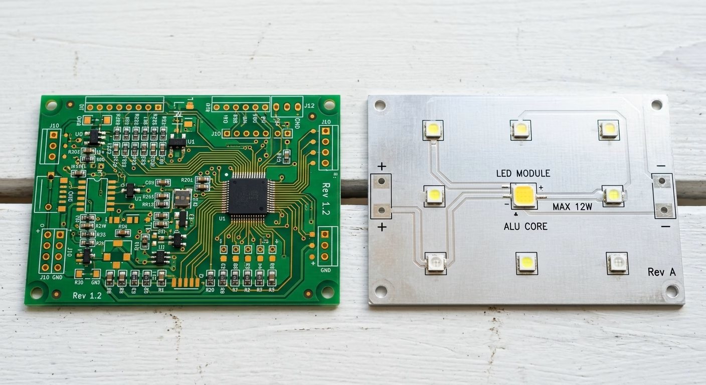
Table of Contents
An aluminum PCB vs FR4 PCB comparison is not a simple contest between a “better” and a “cheaper” material. It is a decision about the dominant constraint in your product: heat removal, routing density, electrical isolation, weight, vibration, cost, or manufacturing flexibility.
FR-4 remains the practical baseline for most general-purpose electronics because it supports complex multilayer routing at a mature, predictable cost. An aluminum PCB, also called a metal-core PCB (MCPCB), earns its place when a component’s heat must move through the board and into a chassis or heatsink.
The important qualification is that an aluminum base does not guarantee a cool board. The thermal dielectric, copper pattern, component package, mounting interface, airflow, and enclosure determine the finished assembly’s temperature. This guide compares the two constructions by those real design decisions, not by isolated material numbers.
Quick answer: aluminum PCB or FR-4?
Choose an aluminum PCB when all or most of these conditions apply:
- A concentrated heat source, such as a high-power LED, MOSFET, regulator, or resistor, sets the design limit.
- The aluminum base can contact a heatsink, chassis, or other defined heat-rejection surface.
- Your routing fits a single-sided or limited-layer metal-core construction.
- The product benefits from a rigid, metal-backed structure.
- The thermal benefit can offset the added material and process cost.
Choose an FR-4 PCB when these conditions matter more:
- The design needs dense multilayer routing, many vias, or conventional plated through-holes.
- Power dissipation is low or can be handled with copper planes, thermal vias, and a separate heatsink.
- Electrical isolation, controlled impedance, or RF material consistency is the main concern.
- The product must stay light, or the board must be flexible or rigid-flex.
- You want the broadest supplier and process options at the lowest board-level cost.
If you cannot answer where the heat will go after it reaches the board, do not select aluminum yet. First define the entire thermal path from the component junction to ambient.
Key differences at a glance
| Decision factor | Aluminum PCB | FR-4 PCB |
| Main advantage | Heat spreading through a metal base | Routing flexibility and broad process maturity |
| Typical construction | Copper circuit, thermal dielectric, aluminum base | Copper, prepreg/core, and glass-reinforced epoxy laminate |
| Thermal behavior | Strong board-level heat path when mounted correctly | Relies more on copper, vias, airflow, and external thermal hardware |
| Layer-count flexibility | Simplest in single-sided or limited-layer formats; complex multilayer builds need early process review | Mature single-sided, double-sided, and multilayer options |
| Electrical isolation | Depends on the thermal dielectric and clearances from the conductive base | Provided by the laminate system throughout the board |
| Mechanical trade-off | Rigid metal backing, but higher density and special drilling/mounting considerations | Lightweight, rigid laminate with familiar fabrication rules |
| Cost direction | Often higher at board level; may reduce system heatsink cost | Usually lower and easier to source; may require additional thermal hardware |
| Best fit | LED lighting, power conversion, motor control, thermal modules | Control boards, digital electronics, dense mixed-signal designs, general electronics |
The table is directional, not a quote or a universal material specification. FR-4 is a family of laminate systems, and aluminum PCBs use different alloys and dielectric systems. Compare the exact supplier datasheets and finished stackups before freezing the design.
What is an FR4 PCB?
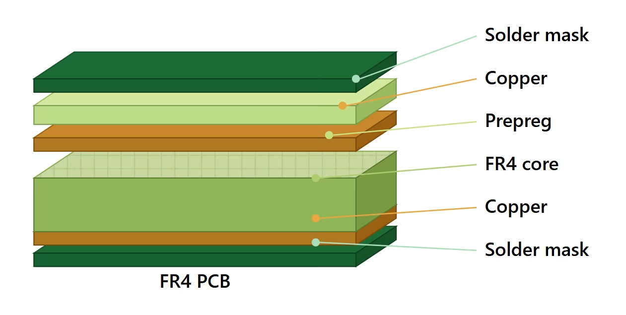
FR4 is arguably the most common and widely used PCB material in the electronics industry. The “FR” stands for Flame Retardant, and “4” signifies a specific grade of material within the NEMA standard. Essentially, an FR4 PCB is made from a woven fiberglass fabric impregnated with an epoxy resin binder, then laminated under heat and pressure. This composition gives FR4 its characteristic rigidity, excellent electrical insulation properties, and good mechanical strength.
Its widespread adoption stems from a combination of factors, including its affordability, ease of manufacturing, and versatility. FR4 provides a stable platform for soldering various electronic components and can be readily fabricated into single-sided, double-sided, and multi-layer configurations. It’s also designed to meet UL 94V-0 flame retardancy standards, ensuring safety in many applications. However, despite its many advantages, FR4 has limitations, particularly when it comes to managing high levels of heat.
Common Applications of FR4 PCBs
Due to its balance of cost, performance, and manufacturability, FR4 is the go-to PCB material for a vast array of consumer electronics and general-purpose applications. These include:
- Consumer Electronics: Smartphones, tablets, laptops, TVs, and home appliances.
- Automotive Electronics: Non-heat critical components like infotainment systems and control units.
- Industrial Controls: Standard control boards and automation systems.
- Networking Equipment: Routers, modems, and switches.
- Medical Devices: Diagnostic equipment and non-implantable devices.
FR4 is ideal for low-to-moderate power applications where excessive heat generation is not a primary concern, making it a cost-effective solution for a broad spectrum of electronic devices.
What is an Aluminum PCB?
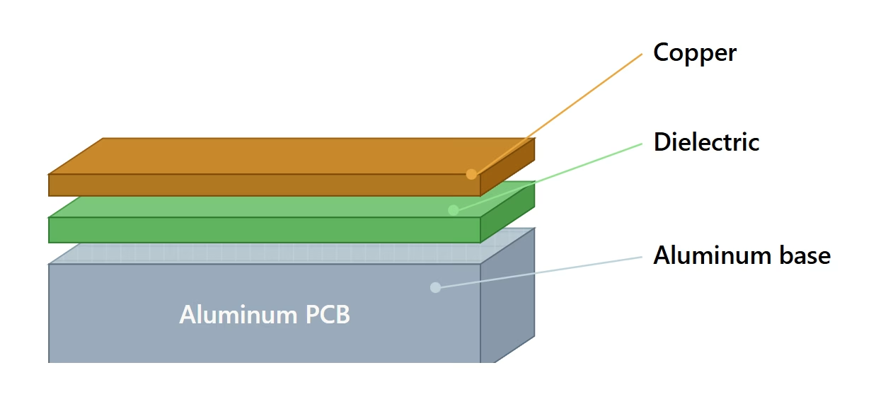
An aluminum PCB places a conductive aluminum base beneath the copper circuit. A thermally conductive, electrically insulating dielectric separates the two layers. The usual single-sided stackup is:
- Copper circuit layer with traces, pads, and thermal lands
- Thermal dielectric that provides isolation and carries heat through the board
- Aluminum base that spreads heat and adds stiffness
The aluminum base is not the only thermal material. In many designs, the dielectric is the bottleneck. Its thickness, thermal conductivity, dielectric strength, bond quality, and temperature rating must be reviewed together.
What an aluminum PCB changes in the design
The metal core affects more than heat:
- The conductive base changes mounting-hole isolation and creepage/clearance decisions.
- The stackup limits how casually you can add layers, vias, and through-holes.
- Aluminum changes routing, drilling, slotting, panelization, and depanelization considerations.
- The board-to-chassis interface becomes part of the electrical and thermal design.
- The assembly process must account for a different board mass, thermal response, and component temperature profile.
See PCBAndAssembly’s aluminum PCB capability for the relevant metal-core construction options.
Aluminum PCB vs. FR4 PCB: A Detailed Comparison
Understanding the fundamental differences between these two PCB materials is crucial for optimal project design. Let’s delve into a side-by-side comparison across several key properties.
Why aluminum can help
An aluminum PCB places a metal heat spreader close to the component side. When the base makes good contact with a chassis or heatsink, heat can move away from a concentrated source without first traveling through a thick region of low-conductivity laminate.
FR-4 can still spread heat through copper planes and thermal vias. It is often enough for low-to-moderate dissipation, especially when the heat source has a large copper area and the enclosure provides airflow or a separate heatsink. The board material alone does not determine junction temperature.
Material Composition and Construction
- FR4 PCB: Composed of woven fiberglass cloth impregnated with epoxy resin. It’s a non-metallic, composite material. The primary structure is layered copper foil, prepreg (epoxy-fiberglass), and core (another layer of prepreg and copper).
- Aluminum PCB: Features a metal base (aluminum alloy) as its foundation. Above this is a dielectric (insulating) layer, followed by the copper circuit layer. The aluminum base provides the high thermal conductivity, while the dielectric layer ensures electrical isolation between the circuits and the metal core.
Thermal Conductivity and Heat Dissipation
This is arguably the most significant distinguishing factor. Aluminum PCBs offer drastically superior thermal management capabilities compared to FR4.
- FR4 PCB: Has a relatively low thermal conductivity (typically around 0.2–0.5 W/m·K). It acts more as a thermal insulator, trapping heat within the board. This limits its use in high-power applications.
- Aluminum PCB: Boasts excellent thermal conductivity (typically 1–8 W/m·K, sometimes even higher with specialized dielectrics). The aluminum core rapidly transfers heat away from hot components, dissipating it into the environment, preventing overheating and improving reliability.
Engineering note: estimate the dielectric contribution
For a simplified through-plane section, use:
Rθ = t / (k × A)
where t is dielectric thickness in meters, k is thermal conductivity in W/m·K, and A is the effective heat-transfer area in square meters.
Illustrative example, not a production guarantee: a 0.10mm dielectric rated at 2.0 W/m·K under a 20mm × 20mm thermal land gives:
Rθ = 0.00010 / (2.0 × 0.0004) = 0.125 K/W
At 4W, that idealized dielectric section contributes about 0.5°C of temperature rise. The result is intentionally incomplete. It excludes spreading resistance, copper constriction, solder, contact pressure, interface material, heatsink resistance, airflow, and neighboring hot components.
The equation follows the thermal-resistance relationship described in ROHM’s thermal design application note. Use it to understand which inputs matter, then validate the finished assembly with a prototype or thermal test coupon.
Electrical Properties
While both provide electrical insulation, their specific properties differ:
- FR4 PCB: Offers good dielectric strength and insulation resistance. Its dielectric constant (Dk) is generally stable across typical operating frequencies, making it suitable for a wide range of electronic components.
- Aluminum PCB: The dielectric layer, though thin, provides excellent electrical insulation between the copper circuit and the conductive aluminum base. The focus here is on maximizing thermal transfer while maintaining electrical isolation.
Mechanical Strength and Durability
Both materials offer good mechanical properties, but with different nuances:
- FR4 PCB: Known for its good rigidity and mechanical strength, making it durable for general applications. It is relatively lightweight.
- Aluminum PCB: Provides superior mechanical strength and rigidity due to the metal core. It is also more resistant to vibration and thermal cycling stresses, which can be advantageous in harsh environments. However, it is also heavier than FR4.
Cost Considerations
Cost is a significant factor, especially for hobbyists and in prototype design stages:
- FR4 PCB: Generally much more affordable. The raw materials are less expensive, and the manufacturing process is highly standardized and efficient, leading to lower per-unit costs, especially for high volumes.
- Aluminum PCB: Typically more expensive. The aluminum substrate itself is more costly than FR4 material, and the specialized dielectric layer adds to the expense. Furthermore, the fabrication processes for metal core PCBs can be more complex, contributing to higher manufacturing costs. However, for applications like LED lighting or power electronics, the long-term benefits of thermal management often outweigh the initial cost.
Electrical Properties Comparison
Electrical performance is a critical factor in PCB selection, especially for applications requiring signal integrity, high voltage isolation, or precision circuit behavior. The table below presents a detailed side-by-side comparison of key electrical properties between FR4 and Aluminum PCBs.
Table 1: Electrical Property Comparison — FR4 vs. Aluminum PCB
| Electrical Property | FR4 | Aluminum |
| Dielectric Constant | 4.2 – 4.6 | 3.7 |
| Loss Tangent | 0.01 – 0.025 | 0.001 |
| Insulation Resistance | >1000 MΩ | 10–25 MΩ |
| Breakdown Voltage | 12 kV/mm | 1.5 kV/mm |
Key Takeaways from Electrical Properties:
- FR4 has a higher dielectric constant (4.2–4.6 vs. 3.7), making it more suitable for applications requiring stable signal propagation at standard frequencies.
- Aluminum PCBs have a significantly lower loss tangent (0.001 vs. 0.01–0.025), meaning less signal energy is dissipated as heat — an advantage in high-frequency or RF-adjacent circuits.
- FR4 offers far superior insulation resistance (>1000 MΩ vs. 10–25 MΩ) and breakdown voltage (12 kV/mm vs. 1.5 kV/mm), making it the preferred choice for high-voltage and precision analog applications.
- For designs prioritizing electrical isolation and signal integrity, FR4 holds a clear advantage. Aluminum PCBs sacrifice some electrical performance in exchange for exceptional thermal management.
Mechanical Properties Comparison
Mechanical robustness determines how well a PCB withstands physical stress during manufacturing, assembly, and in-field operation. The following table compares the key mechanical properties of FR4 and Aluminum PCBs.
Table 2: Mechanical Property Comparison — FR4 vs. Aluminum PCB
| Mechanical Property | FR4 | Aluminum |
| Flexural Strength | 275–380 MPa | 110–350 MPa |
| Tensile Strength | 70–80 MPa | 90–190 MPa |
| Hardness | 100–110 (Rockwell) | 25–50 (Rockwell) |
| Density | 1900–2000 kg/m³ | 2700 kg/m³ |
Key Takeaways from Mechanical Properties:
- FR4 exhibits higher flexural strength (275–380 MPa vs. 110–350 MPa), making it more resistant to bending — ideal for boards subject to mechanical flex.
- Aluminum PCBs outperform FR4 in tensile strength (90–190 MPa vs. 70–80 MPa), offering better resistance to pulling or stretching forces.
- FR4 is significantly harder (100–110 Rockwell vs. 25–50 Rockwell), which helps it withstand surface abrasion and mechanical drilling more effectively.
- Aluminum PCBs are denser (2700 kg/m³ vs. 1900–2000 kg/m³), meaning they are heavier — a consideration for weight-sensitive designs like portable electronics.
- Overall, FR4 is the better choice for general mechanical durability at lower weight, while Aluminum PCBs offer structural rigidity suited for vibration-prone or high-heat environments.
Thermal Performance Comparison
Thermal management is often the decisive factor when choosing between FR4 and Aluminum PCBs. The table below highlights the critical thermal properties of both materials.
Table 3: Thermal Performance Comparison — FR4 vs. Aluminum PCB
| Thermal Property | FR4 | Aluminum |
| Thermal Conductivity | 0.25 W/mK | 237 W/mK |
| CTE (Coefficient of Thermal Expansion) | 14–16 ppm/°C | 23 ppm/°C |
| Thermal Cycles Withstood | 150 (0°C to 100°C) | 2000+ (0°C to 100°C) |
| Max Operating Temperature | 130°C | 660°C |
Key Takeaways from Thermal Performance:
- The thermal conductivity gap is enormous: Aluminum PCBs conduct heat at 237 W/mK, nearly 950 times better than FR4 at 0.25 W/mK. For high-power designs, this difference is decisive.
- Aluminum PCBs can endure 2000+ thermal cycles (0°C to 100°C) vs. only 150 for FR4, making them far more suitable for applications with repeated heating and cooling cycles, such as automotive or industrial equipment.
- The maximum operating temperature of Aluminum (660°C) vastly exceeds that of FR4 (130°C), which opens up aluminum for extreme-environment applications.
- FR4 has a lower CTE (14–16 ppm/°C vs. 23 ppm/°C for aluminum), meaning FR4 expands less with temperature changes — an advantage for maintaining dimensional stability in precision circuits.
- If your design involves high-power LEDs, power modules, or any component that generates sustained heat, an Aluminum PCB is the only viable choice from a thermal standpoint.
Choosing the Right PCB for Your Project
The decision between an aluminum PCB vs FR4 PCB ultimately depends on your project’s specific requirements. There isn’t a universally “better” material; rather, there’s the most appropriate material for a given set of constraints and performance goals.
Consider the following factors when making your choice:
- Thermal Requirements: Is your device expected to generate significant heat? If so, particularly with high-brightness LEDs, high-power resistors, or voltage regulators, an Aluminum PCB is the clear choice for effective thermal management. For lower power applications, FR4 is usually sufficient.
- Cost: If budget is a primary constraint and thermal demands are moderate, FR4 offers a more economical solution. For projects where performance and longevity in high-heat environments are critical, the investment in an Aluminum PCB is justified.
- Mechanical Demands: For applications requiring high rigidity, vibration resistance, or robust structural integrity, the metal core of an Aluminum PCB provides an advantage.
- Electrical Performance: For standard digital and analog circuits without extreme high-frequency requirements, FR4’s electrical properties are usually adequate. FR4 also provides superior insulation resistance and breakdown voltage.
- Application: Specific industries often dictate the material. LED lighting and power electronics are strong candidates for aluminum, while general consumer electronics typically rely on FR4.
| If your answer is… | Start with… | Why |
| High heat, simple routing, defined heatsink interface | Aluminum PCB | Shorter thermal path and metal heat spreading |
| Low heat, dense routing, standard enclosure | FR-4 PCB | More routing freedom and lower process complexity |
| High current and high heat in the same area | Aluminum plus heavy copper evaluation | The metal core handles heat spreading; copper handles current and local loss |
| High voltage on a metal-backed board | Aluminum only after dielectric and isolation review | The base is conductive and requires controlled insulation |
| RF or high-speed signal integrity dominates | FR-4 or RF laminate first | Stackup, loss, and reference-plane control may matter more than base metal |
| Prototype with uncertain thermal behavior | Either, with a defined test plan | Measure the assembly instead of assuming the material will solve it |
FAQ
Which PCB material is better for high-power LED applications?
Aluminum PCBs are significantly better for high-power LED applications due to their superior thermal conductivity and ability to efficiently dissipate heat, which extends LED lifespan and maintains performance.
Is an aluminum PCB always better for high-power electronics?
No. It is often a strong candidate when heat is concentrated and the board can transfer that heat to a defined chassis or heatsink. If the enclosure cannot remove the heat, or if the design needs dense multilayer routing, FR-4 with a properly designed thermal solution may be better.
Can FR4 PCBs be used in applications with some heat?
Yes, FR4 PCBs can handle moderate heat. However, if heat generation is continuous or intense, FR4’s thermal insulating properties can lead to component overheating and reduced reliability. In such cases, an Aluminum PCB would be more suitable for proper thermal management.
Is an Aluminum PCB always more expensive than an FR4 PCB?
Generally, yes. The specialized aluminum core and dielectric layers, along with more complex manufacturing processes, make Aluminum PCBs more costly than standard FR4 PCBs. However, the long-term benefits in specific applications can justify the higher upfront expense.
What does the “FR” in FR4 stand for?
The “FR” in FR4 stands for Flame Retardant, indicating its compliance with specific flame resistance standards, such as UL 94V-0.
Can you solder components directly on an aluminum PCB?
No. Soldering directly on bare aluminum can cause metallurgical issues such as solder voids, dissolution of aluminum into the solder, and oxidation. Engineers typically install copper pads on the outer layers for component soldering, sometimes with protective coatings like nickel or gold on areas requiring soldering.
Are aluminum PCBs prone to corrosion?
Yes, when exposed to moisture, bare aluminum can develop surface oxidation and corrosion. This is why PCB substrates must have protective layers such as lacquers, anodization layers, or conformal coatings, which shield the board from harsh environments.
Does aluminum PCB provide electrical shielding?
The metal base can influence shielding when it is electrically connected and mechanically positioned for that purpose, but it is not an automatic EMI solution. Treat shielding, grounding, dielectric spacing, and signal integrity as separate design requirements.
What is the main disadvantage of an aluminum PCB?
The main disadvantages are reduced routing flexibility compared with standard multilayer FR-4, additional isolation and mounting constraints, and potentially higher board cost. These trade-offs are justified when board-level thermal management is the main constraint.
Summary
The decision between an aluminum PCB vs FR4 PCB is a critical engineering choice that hinges on the specific demands of your electronic project. FR4 PCBs, with their fiberglass-reinforced epoxy resin construction, offer a cost-effective, versatile, and mechanically strong solution suitable for a vast array of general-purpose and low-to-moderate power electronic components. Conversely, Aluminum PCBs, with their metal core, are purpose-built for efficient thermal management.
For help comparing an aluminum core PCB with an FR-4 stackup, send your design for a PCBAndAssembly DFM review and quote.

Get Quote Free