4 oz PCB: Complete Guide to Heavy Copper for Power Electronics
A 4 oz copper PCB uses copper foil with a finished thickness of approximately 140 µm (5.5 mils) per layer — four times the copper of a standard 1 oz board. This extra copper carries more current, spreads heat more effectively, and delivers the mechanical robustness that power electronics demand.
Get Your PCB Quote!

Table of Contents
If you’ve ever designed a board that carries 30A continuously — a battery management system, a motor drive, or a DC-DC converter — you’ve hit the wall that standard 1 oz copper simply can’t handle. The trace widths become absurdly wide, the board layers multiply just to carry current, and the thermal rise at full load keeps you awake at night. That’s exactly when you need 4 oz PCB copper.
This guide covers everything you need to know about 4 oz PCBs: the electrical and thermal benefits, the real design constraints, the manufacturing challenges you need to account for, and exactly how to specify heavy copper for your next project. Whether you’re designing an EV battery pack monitor or an industrial power supply, the information here will save you from costly prototype spins.
What Is a 4 oz PCB?
A 4 oz PCB refers to a printed circuit board where the copper thickness on specific layers or the entire board is 4 ounces per square foot. This is the standard unit for measuring copper foil thickness in the PCB industry.
Copper Thickness Conversion Table
| Copper Weight | Thickness (µm) | Thickness (mils) | Typical Use |
| 0.5 oz | 17.5 µm | 0.7 mil | Fine-line HDI, high-density designs |
| 1 oz | 35 µm | 1.4 mil | Standard general-purpose, most designs |
| 2 oz | 70 µm | 2.8 mil | Moderate current, power distribution |
| 3 oz | 105 µm | 4.1 mil | High-current power stages |
| 4 oz | 140 µm | 5.5 mil | Heavy-current BMS, motor drives, inverters |
| 6 oz | 210 µm | 8.3 mil | Industrial welding, extreme power |
| 10 oz+ | 350+ µm | 13.8+ mil | Bus bars, high-power switching |
4 oz copper sits in the “heavy copper” category alongside 3 oz, 6 oz, and beyond. Unlike standard 1 oz boards, 4 oz boards require specialized fabrication processes because the copper is too thick for conventional etching lines.
Standard vs Heavy Copper Terminology
The IPC-6012 standard defines heavy copper as any PCB with finished copper thickness of 3 oz (105 µm) or greater on outer layers, or 2 oz (70 µm) or greater on inner layers. By this definition, 4 oz PCBs squarely qualify as heavy copper, and they must be fabricated with the appropriate process controls.
Why Choose 4 oz Copper?
The decision to use 4 oz copper comes down to three factors: current capacity, thermal management, and mechanical reliability.
Current-Carrying Capacity
The cross-sectional area of a copper trace determines how much current it can carry before the temperature rise becomes unacceptable. A 4 oz trace has four times the cross-section of a 1 oz trace at the same width.
| Trace Width | 1 oz (35 µm) — Max Current | 4 oz (140 µm) — Max Current |
| 50 mil (1.27 mm) | 2.5A | 9.8A |
| 100 mil (2.54 mm) | 4.5A | 17.5A |
| 200 mil (5.08 mm) | 8.0A | 31.0A |
| 400 mil (10.16 mm) | 14.0A | 54.0A |
| 1000 mil (25.4 mm) | 28.0A | 108.0A |
Based on IPC-2152 standard, 10°C temperature rise, 1 oz inner layer.
The practical implication is significant: a 200 mil trace on a 4 oz board carries roughly the same current as a 1000 mil trace on a 1 oz board — saving enormous board space.
Thermal Management Benefits
Thick copper does more than just conduct electricity. It also acts as an in-plane heat spreader, conducting heat away from hot components and distributing it across the board.
- Lower IR drop: 4 oz copper has 75% lower resistance per square than 1 oz — less voltage drop under load, less power wasted as heat
- In-plane spreading: The copper layer itself becomes a heatsink, reducing hot-spot temperatures by 15-25°C in typical power designs compared to 1 oz boards
- Via thermal transfer: Thicker copper barrels in plated through-holes conduct heat more efficiently between layers, enabling better vertical thermal management
Mechanical Robustness
4 oz copper layers add significant structural strength to the PCB. Boards with heavy copper layers resist warpage better under thermal cycling and are more resistant to trace damage during assembly and field use.
4 oz PCB Applications
4 oz copper PCBs are the standard choice for power electronics across multiple industries.
Battery Management Systems (BMS)
Modern lithium-ion battery packs for EVs, energy storage, and industrial equipment use 4 oz copper on the main current-carrying layers. The high discharge currents (50-200A+ in EV applications) require thick copper to keep both resistance and temperature within safe limits. The BMS board typically uses heavy copper for the main power paths and standard copper for the monitoring and balancing circuits — a mixed-weight stackup that requires careful planning with your fabricator.
EV Power Electronics
Electric vehicle drivetrains place extreme demands on PCB copper. Onboard chargers, DC-DC converters, and traction inverter driver boards all benefit from 4 oz or heavier copper. The combination of high current, high voltage, and harsh thermal cycling (under-hood temperatures combined with self-heating) makes heavy copper essential for reliability.
Industrial Motor Drives
Variable frequency drives, servo controllers, and industrial power supplies routinely use 4 oz copper for the power stages. IGBT and MOSFET gate driver boards need thick copper to handle the pulsed currents and thermal transients of motor control. Many industrial designs combine 4 oz outer layers with 2-3 oz inner layers for the power distribution planes.
Solar Inverters and Renewable Energy
Grid-tie solar inverters and off-grid power systems use heavy copper for the DC-AC conversion stages. The high continuous DC current from solar panels, combined with the switching currents in the inverter bridge, makes 4 oz copper a natural fit. The same applies to wind turbine converters and fuel cell power conditioners.
UPS and Power Supplies
Uninterruptible power supplies and high-power AC-DC converters use heavy copper for the transformer windings (planar transformers), output rectification stages, and battery charging circuits. 4 oz copper allows these boards to handle the sustained currents without excessive thermal rise.
4 oz PCB Design Guidelines
Designing with 4 oz copper requires different rules than standard PCBs. The thick copper changes etching behavior, impedance, and mechanical properties.
Minimum Trace Width and Spacing
The biggest constraint with 4 oz copper is the etch factor. Because the copper is 140 µm thick, the etchant must work much longer to clear the spaces between traces. During this extended etch time, the etchant also attacks the sides of the traces, causing undercutting.
| Copper Weight | Minimum Trace/Space (Standard) | Minimum Trace/Space (Premium) |
| 1 oz | 3/3 mil | 2.5/2.5 mil |
| 2 oz | 6/6 mil | 5/5 mil |
| 3 oz | 8/8 mil | 7/7 mil |
| 4 oz | 10/10 mil | 8/8 mil |
| 6 oz | 15/15 mil | 12/12 mil |
Critical point: These are minimum values for simple designs. For controlled impedance or high-reliability applications, increase these by at least 20%. Always confirm minimum trace/space with your specific fabricator before finalizing your layout.
Annular Ring Requirements
Thick copper requires larger annular rings. The drilling process can cause copper lifting or cracking at the barrel-to-pad interface, especially if the annular ring is too small.
- Minimum annular ring: 6 mil for 4 oz outer layers (vs 3-4 mil for standard 1 oz)
- Recommended: 8-10 mil for high-reliability designs
- Class 3 requirements: IPC-6012 Class 3 requires minimum 2 mil internal annular ring after fabrication tolerance — for 4 oz boards, start with at least 8 mil on the design
Hole Size and Aspect Ratio
Drilling through thick copper is harder on drill bits and increases the risk of wedge voids (incomplete copper plating inside the hole barrel).
| Board Thickness | 4 oz — Minimum Drill Size | Aspect Ratio |
| 1.6 mm (63 mil) | 0.3 mm (12 mil) | 5.3:1 |
| 2.0 mm (79 mil) | 0.35 mm (14 mil) | 5.7:1 |
| 2.4 mm (94 mil) | 0.4 mm (16 mil) | 5.9:1 |
| 3.2 mm (126 mil) | 0.5 mm (20 mil) | 6.3:1 |
The thicker copper requires more aggressive plating cycles to achieve adequate copper thickness inside the hole barrel. Smaller holes make this exponentially more difficult.
Impedance Considerations
4 oz copper traces have a significantly different impedance profile than standard 1 oz traces. The trace thickness forms a larger portion of the trace height, which affects the microstrip and stripline impedance calculations.
For a given trace width and dielectric height, a 4 oz trace will have: – Lower characteristic impedance (by approximately 5-15% depending on geometry) – Higher capacitance per unit length – More coupling between adjacent traces (thicker traces have more sidewall area)
If your design requires controlled impedance on heavy copper layers, use an IPC-2152 compliant calculator with the actual copper thickness parameter. Do not rely on 1 oz approximations.
For a deeper look at how board thickness affects signal integrity, see our guide on Optimizing PCB Thickness for Signal Integrity & EMI.
Thermal Relief Design
For 4 oz copper, standard thermal relief spoke widths are often insufficient. The thick copper conducts heat more efficiently, which means soldering to a large 4 oz copper pour requires more thermal relief.
- Spoke width: Minimum 12-15 mil (vs 8-10 mil for 1 oz)
- Number of spokes: 4 spokes minimum for through-hole pads, 3 for vias
- Thermal gap: 10-12 mil minimum clearance (vs 6-8 mil for 1 oz)
- Alternative: Consider using via-in-pad with filled vias for SMT power components
Need PCB Manufacturing or Assembly?
Get a free quote within 24 hours. We specialize in prototype-to-production PCB/PCBA for hardware teams worldwide.
4 oz vs 2 oz vs 1 oz: When to Upgrade
Choosing the right copper weight saves cost without compromising performance. Here’s when each weight makes sense.
| Criteria | 1 oz | 2 oz | 4 oz |
| Max recommended current | 5-10A | 15-25A | 30-100A+ |
| Standard trace/space | 3/3 mil | 6/6 mil | 10/10 mil |
| Fabrication availability | Universal | Widely available | Specialist |
| Cost multiplier (vs 1 oz) | Baseline | +15-25% | +30-50%+ |
| Best for | General digital, low-power analog | Medium-power regulation, LED drivers | BMS, motor drives, inverters |
Rule of thumb: If your board has more than 3 power layers to distribute current, you should consider 4 oz copper instead. A single 4 oz plane can often replace two 2 oz or four 1 oz planes — reducing layer count and overall cost.
Manufacturing Challenges with 4 oz Copper
Fabricating 4 oz PCBs is fundamentally different from standard board production. Understanding these challenges helps you design boards that manufacturers can build reliably.
Etching and Undercutting
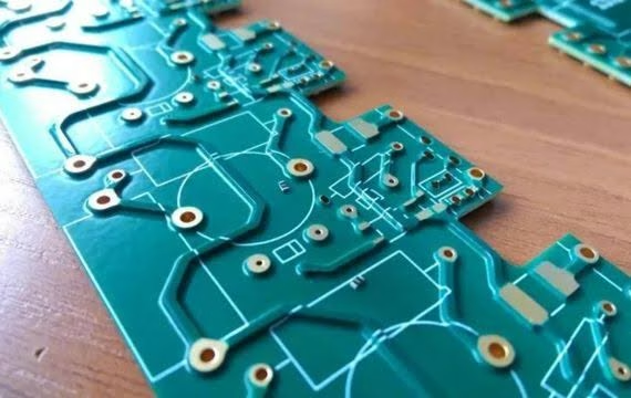
The primary challenge is the etch factor. When etching 4 oz copper, the etchant removes material laterally (sideways) while also etching vertically. This creates a trapezoidal trace profile where the top of the trace is narrower than the bottom.
Practical impact: A 10 mil wide trace on the design file may come out as 7-8 mil at the top surface after etching. Your fabricator will apply etch compensation in CAM — widening the traces on the artwork so the finished traces match your design width. This compensation varies by manufacturer, which is why early communication is essential.
Copper Balancing for Warpage Control
4 oz copper layers create significant internal stress during lamination. If the copper distribution is uneven across layers, the board will warp — sometimes catastrophically.
- Rule 1: Keep copper percentage on each layer as close as possible to the layers above and below
- Rule 2: Avoid large solid copper pours on one side with minimal copper on the opposite side
- Rule 3: For 4 oz inner layers, maintain within 20% copper density between symmetric layers
- Rule 4: Thicker dielectric cores between heavy copper layers help reduce warpage
Wedge Voids and Barrel Integrity
When drilling through 4 oz copper, the drill must cut through the thick copper foil at the hole entrance and exit. This can cause copper lifting or cracking, especially if the drill is dull or the feed rate is too aggressive.
The more serious issue is wedge voids in the plated barrel. After drilling, the hole wall has exposed copper edges from the internal layers. If the electroless copper deposition doesn’t adequately cover these edges, voids form at the layer-to-barrel interface. These voids can cause intermittent connections or outright failures under thermal cycling.
To minimize wedge void risk: – Specify controlled-depth drilling or sequential drilling for complex stacks – Request IPC-6012 Class 3 plating requirements even for Class 2 designs – Confirm the fabricator’s aspect ratio limits for 4 oz copper specifically
Mixed Copper Weight Considerations
Many 4 oz PCBs use mixed stackups — heavy copper on power layers and standard 1 oz copper on signal layers. This saves cost and improves manufacturability, but requires the fabricator to use a hybrid construction approach.
The two common methods are: – Selective plating: Starting with 1 oz base copper, plating up the heavy copper areas to 4 oz – Bonded foil: Using 4 oz copper foil on specific layers with standard foil elsewhere
Selective plating is more cost-effective for most designs but requires the fabricator to confirm their capability with your specific stackup.
4 oz PCB Cost Factors
4 oz PCBs cost significantly more than standard boards, but the premium is often justified by the performance gains.
| Cost Driver | Impact on 4 oz PCB Price |
| Raw material (4 oz copper foil) | +10-15% vs 1 oz |
| Extended etching time | +10-20% process cost |
| Lower yields (etch defects, wedge voids) | +5-15% overhead |
| Specialized drilling (slower feed rates, drill wear) | +5-10% |
| Copper balancing and stackup complexity | +10-25% for mixed weights |
| Sequential lamination (if needed) | +30-50% |
Typical premium range: A 4-layer board with 4 oz outer layers runs approximately 35-60% more than the same board with 1 oz copper. A 6-layer board with mixed 4 oz and 1 oz layers runs 25-45% more. The premium decreases as layer count increases because the heavy copper differential becomes a smaller portion of the overall cost.
For strategies to optimize your board cost, see our guide on How to Reduce PCB Costs: From Materials to Board Size.
Stackup Recommendations for 4 oz PCBs
4-Layer Stackup with 4 oz Outer Layers
For most power applications, 4 oz on the outer layers with standard 1 oz on inner layers provides an excellent balance of current capacity and cost.
| Layer | Function | Copper Weight |
| L1 — Top | High-current power components, thermal pads | 4 oz |
| L2 — Ground | Return path, low-current reference | 1 oz |
| L3 — Power | Secondary power distribution | 1 oz |
| L4 — Bottom | High-current output, through-hole power connectors | 4 oz |
6-Layer Stackup with 4 oz Power Planes
For high-current designs requiring more routing layers, inner-layer power planes can also use 4 oz copper.
| Layer | Function | Copper Weight |
| L1 — Signal | Gate drives, sensing, control logic | 1 oz |
| L2 — Ground | Shield plane, current return | 1 oz |
| L3 — Power | Battery+/DC bus (high current) | 4 oz |
| L4 — Power | Ground return (high current) | 4 oz |
| L5 — Signal | Auxiliary circuits, fault detection | 1 oz |
| L6 — Bottom | Power output, connector pads | 2 oz |
Useful Resources
Industry Standards:
- IPC-6012: Qualification and Performance Specification for Rigid Printed Boards — defines class requirements including copper plating thickness
- IPC-2152: Standard for Determining Current-Carrying Capacity in Printed Board Design — the current reference for trace width calculations (replaces IPC-2221)
- IPC-2221: Generic Standard on Printed Board Design — baseline design rules
Design Tools:
- Saturn PCB Toolkit: Free Windows application with heavy copper trace width calculators based on IPC-2152. Download from saturnpcb.com.
- MWI-2020 Impedance Calculator: For controlled impedance on heavy copper layers
Reference Articles:
- For a full comparison of copper weights, see our 2 oz PCB: Heavy Copper for Power Electronicsguide
- To understand how copper weight affects your overall material choices, read PCB Material Selection: FR-4, Rogers, PTFE & Aluminum
- For detailed trace width calculations at any copper weight, visit our Master PCB Trace Width: Design, Calculate & Optimizeguide
Frequently Asked Questions
What is 4 oz copper in mm?
4 oz copper is 0.14 mm (140 µm) thick. In imperial units, this is 5.5 mils (0.0055 inches). The actual finished thickness can vary by ±10% depending on plating processes and etch compensation, so always confirm the tolerance with your fabricator.
Can I combine 4 oz and 1 oz copper on the same PCB layer?
Not on the same layer using standard processes. Selective plating can create areas of different copper thickness on the same layer, but this requires specialized capability. Most designs either use 4 oz on entire layers or use a separate heavy copper layer paired with standard copper layers in a mixed stackup.
What is the minimum trace width for 4 oz copper?
The reliable minimum for most production fabs is 10 mil (0.25 mm) trace and space. With advanced etching processes and tight process control, 8 mil may be possible — but this reduces yield and increases cost. For high-reliability or Class 3 designs, keep traces at 12 mil or wider.
How much current can a 4 oz PCB carry?
A 1-inch-wide (25.4 mm) 4 oz trace on an outer layer can carry approximately 108A with a 10°C temperature rise. A 200 mil (5 mm) trace carries approximately 31A under the same conditions. For precise calculations, use IPC-2152 compliant tools and account for the number of copper layers and the board’s thermal environment.
Does 4 oz copper affect PCB impedance?
Yes, significantly. The additional copper thickness changes the trace geometry, lowering characteristic impedance by 5-15% compared to 1 oz traces with the same width and dielectric spacing. Always re-run your impedance calculations with the actual 4 oz copper thickness parameter rather than assuming standard values.
Is 4 oz PCB suitable for automotive applications?
Yes, 4 oz PCBs are widely used in automotive power electronics — particularly for EV battery management systems, DC-DC converters, and onboard chargers. For automotive use, specify IATF 16949-compliant fabrication and IPC-A-610 Class 3 assembly standards. Also consider high-Tg FR-4 or polyimide materials to handle the extended temperature range (-40°C to +125°C) typical of automotive environments.
What is the cost difference between 4 oz and standard 1 oz PCB?
Expect a 35-60% premium for a 4-layer board with 4 oz copper on outer layers compared to the same board with 1 oz copper. The premium is driven by longer etching cycles, lower yields, specialized materials, and additional process steps. For mixed-weight stackups (4 oz on some layers, 1 oz on others), the premium is typically 25-45%.
How do I get a quote for a 4 oz PCB?
Submit your Gerber files and stackup specification to your fabricator with explicit copper weight requirements. For best results, include a fabrication drawing that specifies copper weight per layer, minimum trace/space, and IPC class requirements. Expect a longer quote turnaround than standard boards — many manufacturers need to review a 4 oz design with their engineering team before quoting.
Conclusion
4 oz copper PCBs are the standard choice for power electronics that need to carry 30A or more continuously. The thicker copper reduces resistance, spreads heat, and eliminates the need for multiple power layers that would otherwise be required with 1 oz or 2 oz material.
The trade-off is in manufacturing complexity. You can’t design a 4 oz board the same way you design a standard board — trace widths must be wider, spacing looser, annular rings larger, and copper distribution carefully balanced. But when your design calls for high current capacity in a compact form factor, 4 oz copper is often the only practical solution.

Get Quote Free