PCB BOM: How to Fill Each Field and Check for Errors
Learn how to fill a PCB BOM, verify MPN suffixes and Imperial/Metric packages, handle DNP parts, and cross-check assembly files before submission.
Get Your PCB Quote!
Table of Contents
- What Is a PCB BOM—and How Does It Work with Other Assembly Files?
- How to Fill Each PCB BOM Field
- Annotated PCB BOM Example: Read and Check Every Column
- Resolve Three Frequent BOM Mix-ups
- Incorrect vs. Correct BOM Rows—and How to Fix Them
- Pre-Submission Checklist: Match BOM, Placement File, and Assembly Drawing
- PCB BOM FAQ
Table of Contents
- What Is a PCB BOM—and How Does It Work with Other Assembly Files?
- How to Fill Each PCB BOM Field
- Annotated PCB BOM Example: Read and Check Every Column
- Resolve Three Frequent BOM Mix-ups
- Incorrect vs. Correct BOM Rows—and How to Fix Them
- Pre-Submission Checklist: Match BOM, Placement File, and Assembly Drawing
- PCB BOM FAQ
A PCB Bill of Materials (BOM) is the master component list that tells your assembler which parts to buy, where to place them, and how many are needed per board. A production-ready BOM ties every component to a complete Manufacturer Part Number (MPN), an unambiguous per-board quantity, an explicit fitted status (Fitted vs. DNP), and the exact PCB revision and assembly variant.
BOM Readiness at a Glance — 5 Rules Before You Send
- Identify parts by Manufacturer + complete MPN: Never rely on a generic value (
10k), truncated code, or distributor link alone. - Separate design count from purchase quantity: Per-board quantity belongs in the BOM; attrition, spares, and MOQ belong on the purchase order.
- Keep
DNP,Variant, andSupplyin separate columns: Customer-supplied parts are stillFitted, notDNP. - Specify Imperial vs. Metric package codes: Imperial
0603(1.6 × 0.8 mm) is much larger than Metric0603(0.6 × 0.3 mm / Imperial0201) and uses incompatible land patterns. - Reopen the exported file after saving: Inspect
.csvor.xlsxexports to catch Excel date conversions, stripped leading zeros, and broken portal mappings.
What Is a PCB BOM—and How Does It Work with Other Assembly Files?
Your assembly BOM defines what goes on the board; your fabrication files, placement file, and assembly drawing define where and how it is built. Keeping each document focused prevents conflicting instructions across engineering, purchasing, and the SMT line.
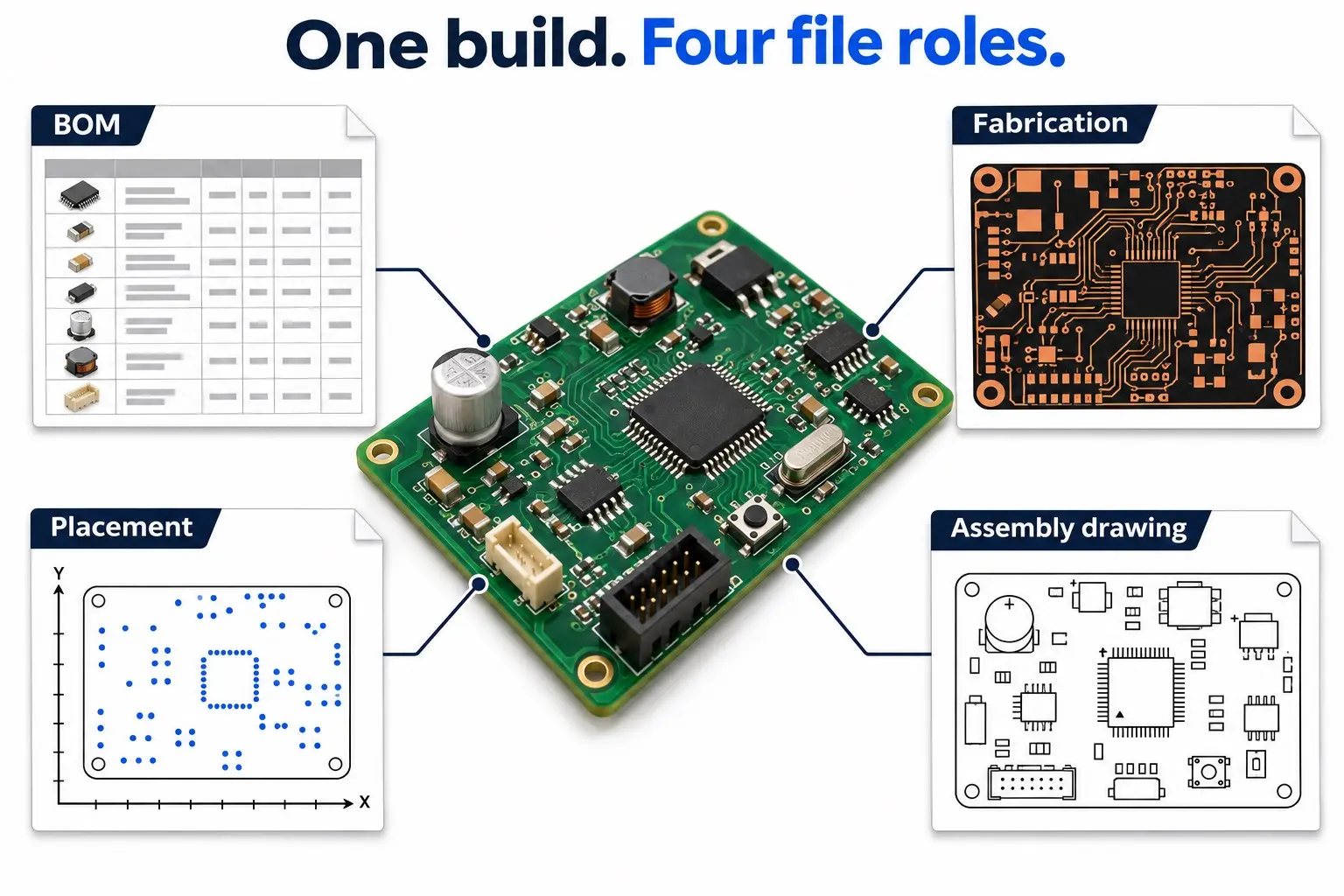
| Assembly File | Primary Question Answered | Key Fields to Cross-Check |
|---|---|---|
| Assembly BOM | Which parts go on this build, at which designators, and in what quantity? | Manufacturer, complete MPN, description, package, Fitted/DNP status, supply owner |
| Bare-Board Fabrication Data | What board geometry, layer stackup, and drill specs must be manufactured? | Board ID, PCB revision, Gerber / ODB++ / IPC-2581 layers, drill files, fab notes |
| Placement File (P&P / Centroid / CPL) | Where is each SMD part placed (X/Y), on which side, and at what rotation? |
Reference designators, units (mm/mil), board origin, top/bottom layer, rotation |
| Assembly Drawing | What visual cues and special rules govern orientation and hand-soldering? | Pin-1 dots, diode/cap polarity, DNP outlines, mechanical hardware, coating notes |
Format note on Gerber X3 and IPC-2581: Traditional Gerber RS-274X carries 2D board layer images (such as copper, solder mask, and silkscreen) without structured BOM data, whereas Gerber X3 and IPC-2581 can embed component and BOM data in the CAD export. Even when exporting those formats, confirm whether your contract manufacturer still requires a standalone .xlsx or .csv BOM for quoting and ERP import.
Why placement row counts rarely match BOM row counts: Depending on exporter settings and assembler preferences, placement exporters (such as KiCad 9.0 PCB Editor) often filter out DNP parts and through-hole (THT) components while adding fiducials. A grouped BOM row like R1, R2 (1 row) also expands into 2 rows in the placement file. Always compare expanded reference designator sets within the same mounting scope rather than raw row counts.
How to Fill Each PCB BOM Field
We recommend a 5-item header block plus 10 core columns (and 1 optional purchasing column) so purchasing and production can verify each row without guessing.
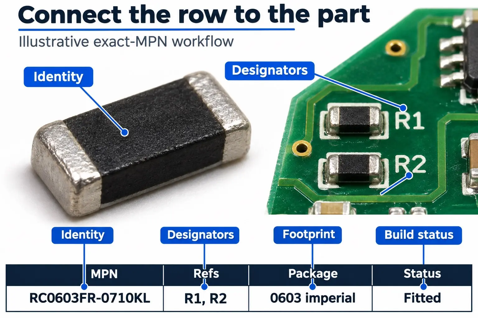
Header Metadata (Place at the Top of the Sheet or Cover Tab)
Include these five identifiers on every release so your BOM cannot be paired with the wrong bare board:
DEMO-BOM-012. PCB Rev:
Rev A3. Variant:
BASE4. BOM Rev & Date:
01 / 2026-11-105. Qty Rule:
Positions per boardField-by-Field Specification Table
| Field | What to Enter | Valid Example | How to Verify | Action If Check Fails |
|---|---|---|---|---|
| Reference Designators | Every individual position (expand ranges like R1-R5) |
R1, R2 |
Count listed references; check for duplicates against schematic | Fix schematic/PCB sync before editing the spreadsheet |
| Quantity per Board | Exact count matching your stated convention | 2 |
Must equal the designator count under Positions per Board (or 0 for DNP rows under Fitted Qty) |
Split DNP items or recount designators |
| Manufacturer | Full component maker name | YAGEO |
Match the official component datasheet | Replace generic labels with approved maker |
| Manufacturer Part Number (MPN) | Complete ordering code, including all suffixes | RC0603FR-0710KL |
Verify every character against datasheet ordering table | Never truncate suffixes; confirm packaging/RoHS codes |
| Description / Spec | Key electrical values for quick human sanity-checks | 10 kΩ, ±1%, 0.1 W @ 70 °C, Thick Film | Confirm value, tolerance, voltage, and dielectric match MPN | Resolve any MPN vs. description mismatch immediately |
| Package / Footprint | Standard case code with unit system + PCB footprint name | 0603 Imperial (1608 Metric) | Compare datasheet body dimensions against PCB land pattern | Update footprint or MPN if pad geometry differs |
| Fitted Status | Whether the part is populated in this variant | Fitted or DNP | Cross-check against the selected design variant | Move DNP positions to their own row |
| Supply Responsibility | Who procures and delivers the component | Turnkey (Assembler) or Consigned (Customer) | Match against your RFQ/kitting agreement | Do not mark consigned parts as DNP |
| Distributor & SKU (Optional) | Supplier catalog code for purchasing convenience | DigiKey: 311-10.0KHRCT-ND |
Confirm the SKU maps 1:1 to the exact MPN | Remove or update if SKU points to a different reel/suffix |
| Approved Alternate | Exact pre-approved substitute MPN + scope | Vishay CRCW060310K0FKEA (R1, R2) |
Verify pinout, ratings, and engineering sign-off | Remove vague notes like “or equivalent” |
| Assembly Notes | Special mounting, polarity, or handling instructions | Hand-solder after reflow; no-clean flux | Ensure notes do not contradict Fitted or Supply columns |
Move structured data into dedicated columns |
Why Complete MPN Suffixes Matter
Truncating an MPN breaks automated quoting and risks receiving the wrong package, temperature grade, or reel orientation.
- In YAGEO’s
RC0603FR-0710KL,0603is the size,Fis ±1% tolerance,Ris paper tape reel,07is 7-inch reel,10Kis resistance, andLindicates lead-free/RoHS termination. - In Texas Instruments’
LM358DR,Dspecifies the 8-pin SOIC package andRspecifies Tape & Reel (whereasPis PDIP through-hole andDGKis VSSOP—completely incompatible footprints).
Exact MPN vs. Specification-Based Passives
Use exact MPNs by default; use specification-based lines only when your assembler explicitly supports generic passives. Some prototype assemblers allow generic resistor/capacitor selection from their house reel library. Even then, “10k” is insufficient—specify value, tolerance, power/voltage rating, dielectric (X7R vs. Y5V), and Imperial/Metric package so circuit margins are protected.
Package Size Trap: Imperial 0603 vs. Metric 0603
Never write 0603 or 0402 without stating the unit system:
- Imperial
0603= 0.06″ × 0.03″ (1.6 mm × 0.8 mm, Metric1608) — standard general-purpose SMD size. - Metric
0603= 0.6 mm × 0.3 mm (Imperial0201) — ~2.67× shorter per side (~7.1× smaller area); will not fit Imperial0603pads. - Imperial
0402= 1.0 mm × 0.5 mm (Metric1005) vs. Metric0402= 0.4 mm × 0.2 mm (Imperial01005).
When to Group vs. Split Identical Parts
Group identical MPNs onto one row only when every build instruction matches. In KiCad 9.0’s BOM exporter, grouping depends on the selected fields. Always split rows if components share an MPN but differ in:
- Fitted status:
R1, R2areFitted, whileR3isDNP. - Supply responsibility: Assembler buys
C1, customer consignsC2. - Approved alternate scope: Alternate approved for
R1pull-up, but notR4precision divider.
Annotated PCB BOM Example: Read and Check Every Column
Follow how each row below links designator, quantity, identity, status, and supply ownership. (Note: DEMO-BOM-01 is a fictional teaching example built with real manufacturer part numbers.)
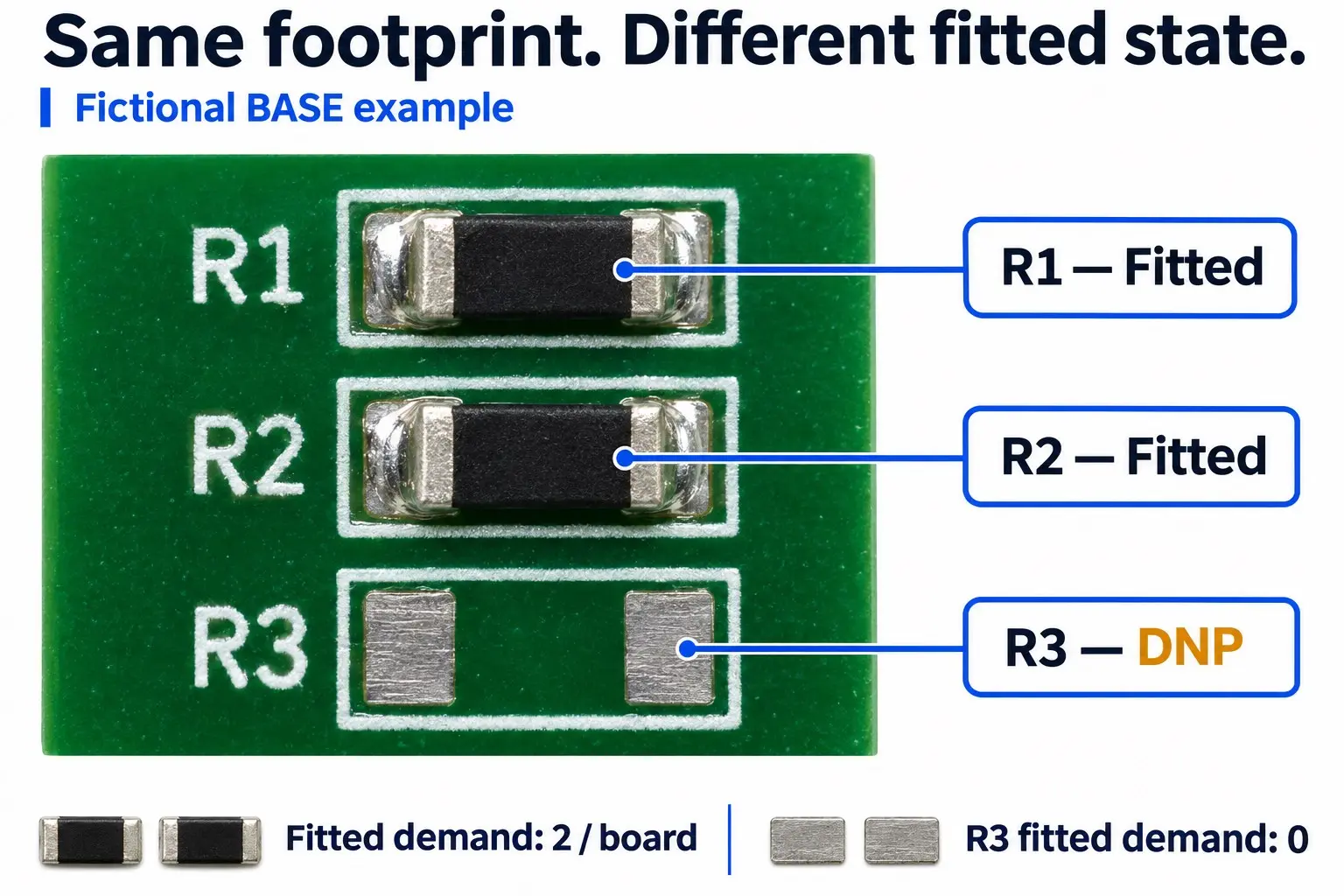
DEMO-BOM-01 · PCB Rev A · BOM Rev 01 · Variant BASE · Release 2026-11-10Quantity Convention: Positions per Board (lists all designators, including
DNP slots; procurement demand is calculated from Fitted rows only).| References | Qty | Manufacturer / Complete MPN | Description | Package | Fitted Status | Supply Owner |
|---|---|---|---|---|---|---|
R1, R2 |
2 | YAGEO / RC0603FR-0710KL |
10 kΩ, ±1%, 0.1 W @ 70 °C Thick Film Resistor | 0603 Imperial (1608 Metric) | Fitted | Assembler |
C1 |
1 | YAGEO / CC0603KRX7R9BB104 |
100 nF (0.1 µF), ±10%, 50 V, X7R MLCC | 0603 Imperial (1608 Metric) | Fitted | Assembler |
U1 |
1 | Texas Instruments / LM358DR |
Dual Op-Amp, 30 V, 700 kHz GBWP | 8-SOIC (D package) |
Fitted | Assembler |
J1 |
1 | Samtec / TSW-102-07-G-S |
2-Pin THT Header, Single Row | 2.54 mm (0.100″) pitch | Fitted | Customer |
R3 |
1 | YAGEO / RC0603FR-0710KL |
10 kΩ, ±1% Resistor (unpopulated in BASE) |
0603 Imperial (1608 Metric) | DNP | N/A |
Column-by-Column Check Notes:
R1, R2vs.R3(Same MPN, Split Rows):R3uses the same resistor MPN asR1, R2, but stays on its own row because it isDNPin theBASEvariant.C1(Critical Specs Beyond Capacitance): 100 nF equals 0.1 µF, and choosing 50 V with X7R dielectric provides better margin than low-voltage or Y5V parts—though X7R still experiences DC bias derating, so verify effective capacitance against the part’s DC bias curve at your operating voltage.U1(Exact Package Suffix): KeepingDRensures the assembler quotes the 8-SOIC (D) footprint in Tape & Reel rather than PDIP or VSSOP.J1(Consigned + THT):J1is customer-supplied and through-hole. It remainsFitted(it must be hand- or wave-soldered) and may be absent from an SMD-only placement file.R3(DNP Quantity Convention): Under Positions per Board,R3showsQty = 1withFitted Status = DNP(0 fitted demand). If your assembler’s template uses Fitted Qty per Board, setR3to0or omit it per their variant rules.
Resolve Three Frequent BOM Mix-ups
1. Manufacturer Part Number (MPN) vs. Distributor SKU vs. Internal PN
An MPN identifies the physical component; a distributor SKU identifies only one vendor’s listing. Never paste a DigiKey, Mouser, or LCSC code into the MPN column. If that distributor runs out of stock, the assembler cannot cross-reference an alternative supplier without the original manufacturer name and MPN. Keep MPN, Distributor SKU, and your Internal Company PN in three separate columns (matching how KiCad’s IPC-2581 exporter separates manufacturer and distributor part fields).
2. Quantity per Board vs. Purchase Quantity (Attrition & Overages)
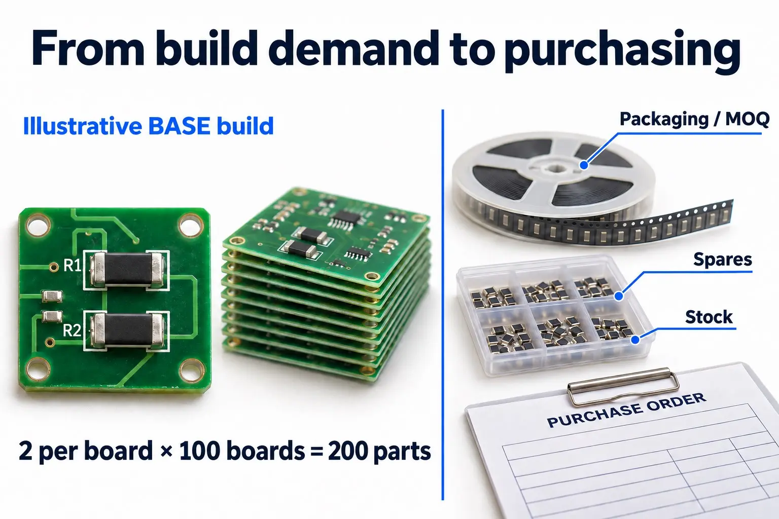
The BOM quantity column must always equal the per-board design count—never multiply it by your build volume or add attrition inside the BOM.
- Design demand example: For 100
BASEboards,R1, R2require 2 × 100 = 200 fitted resistors, whileR3(DNP) requires 0. - Why purchase quantity is higher: SMT pick-and-place feeders require empty leader tape (or extra components) to thread into the feeder, alongside mispick attrition and Minimum Order Quantities (MOQ). If you consign parts, confirm the exact feeder leader-tape, overage, and continuous cut-tape requirements with your assembler based on their feeder type, packaging, and build volume.
3. DNP vs. Assembly Variant vs. PCB Revision
DNP is a per-position instruction, a Variant is a build configuration, and a Revision is a controlled design change.
- DNP (Do Not Populate): The pads exist on the bare PCB, but no component is placed in this build.
- Assembly Variant: A named build option (e.g.,
BASEvs.PRO) that togglesFitted/DNPor swaps an MPN on the same bare PCB. - Revision (
Rev A→Rev B): A formal change to copper, schematic, or BOM documentation. Always specify both PCB Revision and Assembly Variant in your release header.
Incorrect vs. Correct BOM Rows—and How to Fix Them
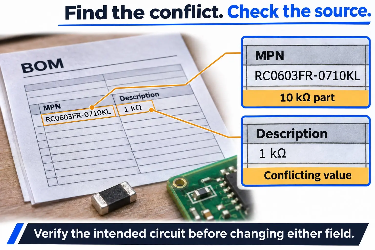
Never “fix” a conflicting BOM row by guessing which column is right—always check the schematic and datasheet first.
| Broken / Ambiguous Entry | Root Risk | Corrected Entry / Action | Stop & Escalate If… |
|---|---|---|---|
| Description: “10k”, no MPN | Assembler cannot verify tolerance, wattage, or package | YAGEO / RC0603FR-0710KL (or full agreed spec) |
STOP Circuit tolerance/wattage is unknown |
R1, R2, R3, Qty 2, Fitted |
Designator count (3) contradicts Qty (2) | Split R3 to a DNP row, or update Qty to 3 |
STOP Schematic doesn’t clarify R3 status |
311-10.0KHRCT-ND in MPN |
Distributor SKU blocks multi-source quoting | Move SKU to Distributor SKU; put RC0603FR-0710KL in MPN |
STOP SKU maps to multiple reel/cut-tape options |
RC0603FR-0710KL labeled 1 kΩ |
MPN is 10 kΩ, description says 1 kΩ (10× error) | Verify schematic value, then fix either MPN or description | STOP Unclear whether circuit needs 1 kΩ or 10 kΩ |
| Package: “Small SMD” or “0603” | Imperial 0603 vs. Metric 0603 (0201) mismatch | 0603 Imperial (1608 Metric) + footprint name |
STOP Pad dimensions on PCB don’t match part |
| Alternate: “or equivalent” | Uncontrolled substitution risks wrong pinout/dielectric | Vishay CRCW060310K0FKEA (R1, R2) or None |
STOP Engineering hasn’t approved any alternate |
Customer-supplied J1 marked DNP |
Assembler will skip soldering J1 |
Fitted = Yes; Supply = Customer |
STOP Kitting responsibility is unconfirmed |
Portal import ignores DNP column |
Automated importer quotes/places DNP parts |
Remap columns in portal; re-verify preview | STOP Portal still shows DNP parts as active |
Watch Out for Spreadsheet & CSV Formatting Traps
Opening or saving a BOM in Excel can silently corrupt data before you send it:
- Date auto-conversion: Part numbers like
10-01orMAR-04turn into dates (Oct-01). Format MPN columns as Text before pasting. - Stripped leading zeros & scientific notation:
0603becomes603; long numeric codes turn into1.23E+11. - Broken
.csvcolumns & symbols: Unquoted commas inside descriptions (10k, 1%, 0603) can shift columns, and encoding mismatches (non-UTF-8 exports or Excel misreading UTF-8) turnΩor±into garbled characters (Ω)—use UTF-8 or ASCII units (kOhm,uF,+/-).
Pre-Submission Checklist: Match BOM, Placement File, and Assembly Drawing
Run these 8 checks in order on your final exported files—not inside your CAD tool—before sending the RFQ or production package.
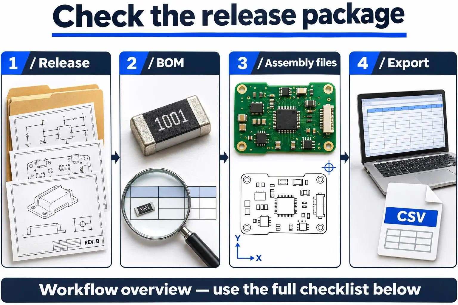
- 1. Lock the Release Package: Confirm your release manifest maps the BOM, Gerbers/ODB++, placement file, and assembly drawing to the exact same PCB Revision and Assembly Variant.
- 2. Audit Designators & Grouping: Expand any hyphenated ranges (
R1-R4), confirm zero duplicate designators, and verify each row’sQtymatches its designator count. - 3. Verify Fitted vs. DNP Counts: Confirm every
DNPslot is isolated fromFittedrows and uses the assembler’s expected quantity rule (Positions vs.0). - 4. Cross-Check MPN, Specs, Lifecycle & Footprint: Confirm every MPN is
Active(not NRND/Obsolete), matches its description, and matches the PCB land pattern (especially Imperial vs. Metric chip sizes and exposed thermal pads). - 5. Confirm Supply Ownership & Alternates: Ensure every
Fittedrow is markedAssemblerorCustomer, and every alternate names an exact MPN with approved reference scope. - 6. Reconcile BOM vs. Placement File by Scope: Compare expanded
Fitted SMDdesignators in the BOM against the placement file. VerifyTHTparts, mechanical hardware, and fiducials separately. - 7. Check Polarity & Orientation on the Assembly Drawing: Verify Pin-1 markers, diode/capacitor polarity, and
DNPcallouts on the assembly drawing match the BOM and placement rotation. - 8. Reopen Exported Files & Inspect Portal Mapping: Open the final
.xlsx/.csvin a text editor or spreadsheet to confirm zero truncated MPNs or shifted columns. Inspect online portal previews to verifyDNPandCustomer Suppliedflags mapped cleanly.
For the broader RFQ package, see the PCB assembly quote checklist and PCB DFM checklist.
PCB BOM FAQ
Can I submit a BOM without exact MPNs?
Yes—only if your assembler explicitly supports specification-based selection for generic passives. You must still provide complete electrical and mechanical parameters (value, tolerance, voltage/power rating, dielectric, and Imperial/Metric package) and confirm approval rules. For ICs, connectors, and critical components, always provide the complete MPN.
Should I group identical parts into one row?
Yes, provided their MPN, fitted status, supply responsibility, and approved alternates are identical. List every reference designator on that row and verify the quantity. Split rows immediately if one position is DNP or customer-supplied.
Must DNP parts appear in the BOM?
It depends on your assembler’s template—both methods work if stated explicitly. Keeping DNP rows in the BOM with Fitted Status = DNP (and 0 fitted demand) gives the clearest audit trail. If your workflow omits DNP rows, note that clearly on the assembly drawing and variant sheet.
Does every BOM item need a pick-and-place entry?
No—placement files typically cover fitted SMD components only. Through-hole connectors, mechanical hardware, heatsinks, and DNP parts are often excluded from the P&P export, while fiducials may appear in P&P without being in the BOM. Reconcile designators within the same mounting scope.
Is a distributor link enough to identify a component?
No—always put the Manufacturer and complete MPN in text columns. Distributor links break, go out of stock, or point to specific packaging/MOQs. Treat distributor URLs and SKUs as supplemental purchasing references only.
PCB BOM • NEXT STEP
Bring a Clear BOM to Your Assembly Discussion
OrinewPCB lists PCB fabrication and assembly among its services. Share your BOM with the matching board files, assembly variant, required build quantity, and any customer-supplied parts to align sourcing and assembly scope before ordering.
- +PCB fabrication
- +PCB assembly
Get Quote Free