Selective Soldering vs Wave Soldering: When Mixed-Technology PCB Assemblies Need It
Selective soldering is not automatically required just because a PCB combines SMT and through-hole parts. Choose the route by three things: what the board underside allows, what the joints and assembly require, and how the setup fits the order volume and product mix. The result may be wave, selective, or a hybrid route. This guide turns those checks into a route screen, a quote comparison, and a route-ready RFQ.
Get Your PCB Quote!
Table of Contents
- Quick Answer: Mixed Technology Alone Does Not Require Selective Soldering
- Start With the Board Underside, Not the Machine Name
- When Wave Soldering Still Wins
- When Selective Soldering Becomes the Practical Route
- When Not to Force Wave or Selective Across the Whole Board
- Standards Define Requirements; They Do Not Pick the Machine
- What Actually Changes the Quote
- Send a Route-Ready RFQ, Not a BOM Alone
- FAQ
- Ready to Request a Board-Specific Soldering Review?
- About This Guide
- References & Sources
- Related Articles
Table of Contents
- Quick Answer: Mixed Technology Alone Does Not Require Selective Soldering
- Start With the Board Underside, Not the Machine Name
- When Wave Soldering Still Wins
- When Selective Soldering Becomes the Practical Route
- When Not to Force Wave or Selective Across the Whole Board
- Standards Define Requirements; They Do Not Pick the Machine
- What Actually Changes the Quote
- Send a Route-Ready RFQ, Not a BOM Alone
- FAQ
- Ready to Request a Board-Specific Soldering Review?
- About This Guide
- References & Sources
- Related Articles
Quick Answer: Mixed Technology Alone Does Not Require Selective Soldering
Wave soldering presents many intended underside joints to a broader solder wave. A carrier or pallet usually controls which areas are exposed. Selective soldering applies a localized solder wave or nozzle to programmed through-hole joint areas. It can be understood as a wave-soldering variant built around local fluxing, preheating, and solder application.
Reflow belongs in the same assembly plan, but it answers a different question. It covers the SMT attachment stage. Wave, selective, hand, robotic, or hybrid routes may then be reviewed for the remaining through-hole joints. This boundary is also reflected in detailed process comparisons. For a closer look at the adjacent process choice, see this wave soldering vs reflow soldering guide.
If you are still choosing between package technologies, start with the SMT vs through-hole component guide.
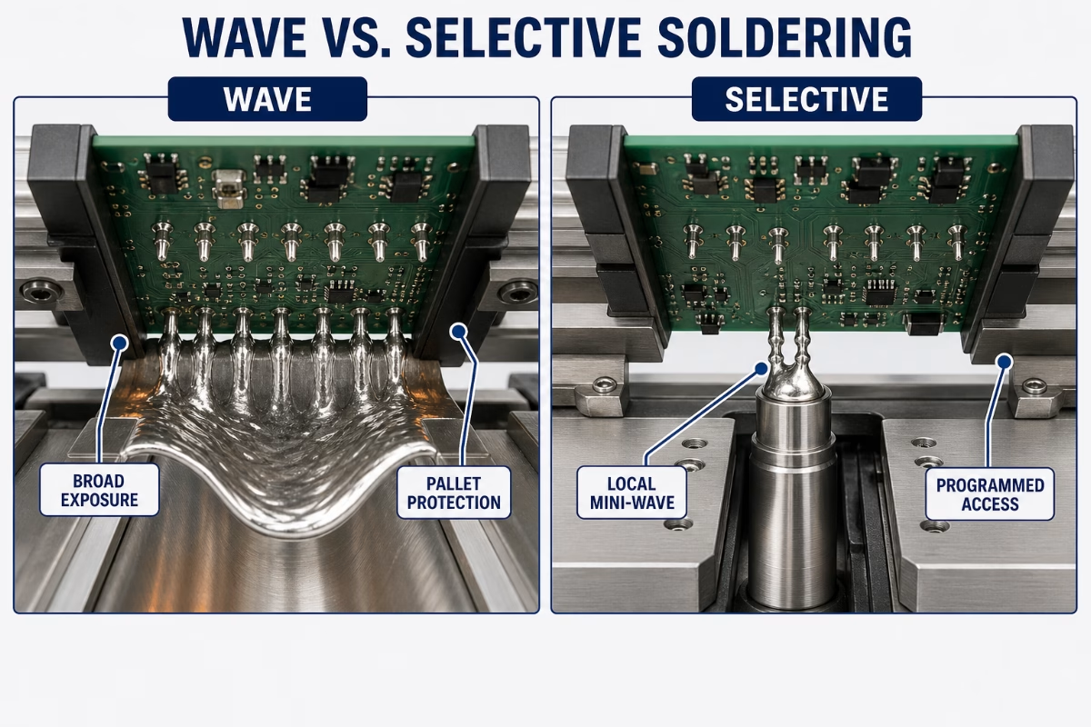
Use this first screen:
| Board condition | Route to keep on the shortlist | What must still be confirmed |
| Many intended THT joints share a wave-ready underside | Wave | Pallet/opening design, board support, process window, and inspection |
| Intended THT joints are isolated or crowded by protected underside features | Selective | Nozzle/path access, support, programming, process window, and inspection |
| Different joint groups have different access or process needs | Hybrid route | Sequence, tooling, ownership of each joint group, and verification |
| Files do not show bottom-side population or special requirements | No route approval yet | Complete assembly data and acceptance/test requirements |
Do not turn this screen into a final process instruction. Its job is to show which routes deserve engineering review.
Start With the Board Underside, Not the Machine Name
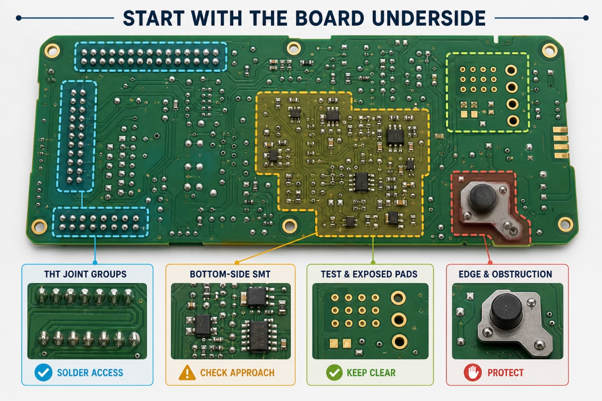
A BOM is not enough to choose between selective and wave soldering. It lists parts. It does not show whether solder can reach the intended joints without exposing, shadowing, or obstructing other features.
Open the fabrication data, placement file, and assembly drawings together. Mark the through-hole pin groups that must be soldered. Then mark nearby bottom-side SMT parts, exposed pads and test points, board edges, tall components, and areas with special handling notes. These are the features that turn a generic process comparison into a board-specific route decision.
The useful question is not which process is more precise. It is whether the proposed tooling or solder path can reach every intended joint while controlling exposure around it.
| Check on the populated underside | What it changes | What the buyer should send |
| Location and grouping of all THT joints | Wave openings/exposure and selective joint groups/path | Gerber/ODB++, assembly drawing, and marked THT groups |
| Bottom-side SMT and exposed copper/test features | Protection, usable pallet openings, and local nozzle/path access | Bottom placement file and protected-area notes |
| Tall parts, board edges, and mechanical obstructions | Carrier, pallet, approach, support, and local access assumptions | Mechanical drawing, component heights, and panel drawing |
| Board construction and copper distribution | Heat-transfer, preheat, and process-development questions | Fabrication drawing and stackup when available |
| Panel and board-support conditions | How the assembly can be held and kept stable through the proposed route | Panel drawing, breakaway method, and support constraints |
Contract-manufacturer guidance identifies two common scenarios for selective soldering review. Tight THT-to-SMT spacing can leave too little room for a protective wave fixture, while thick boards or heavy copper can make hand soldering more difficult. Treat these points as reasons to request DFM feedback rather than as universal clearance or temperature rules. More details are available in this selective vs wave soldering overview.
If a quote names the process but does not show the underside-access assumption, ask for the missing review. Two suppliers can quote different routes because they made different assumptions from the same incomplete package.
When Wave Soldering Still Wins
Wave soldering still belongs on the shortlist when two things hold: the board is designed for it, and the build repeats under stable assumptions. Selective soldering is not a universal upgrade.
The underside is wave-ready
Wave is strongest when intended through-hole joints can meet the solder wave consistently. It also needs other underside features protected without impractical pallet openings. Component placement, exposed features, board support, and panel design all belong in that review.
Ask for the proposed pallet or exposure logic before approving the route. A supplier should be able to explain which areas see solder and which do not. The site’s DIP and wave soldering guide provides more context on where that process still fits in modern PCBA.
The build supports its tooling and setup
Wave economics improve when the same design repeats. The tooling and setup can then carry over across the expected releases. The relevant inputs are not just annual quantity. Product variants, revision frequency, THT joint distribution, pallet maintenance, inspection, and changeovers also affect the comparison.
Do not ask, “At what volume does wave become cheaper?” without supplying the build pattern. Ask the supplier to price the chosen route under your quantity, repeat, and revision assumptions.
The inspection plan covers the actual risks
Wave is not approved because it is fast. It is approved when the process and verification plan meet the assembly’s documented requirements.
Request the inspection method for the difficult joints and the response to a nonconforming result. That answer is more useful than a general claim about yield or reliability.
When Selective Soldering Becomes the Practical Route
Selective soldering becomes practical when local access solves a board-specific problem. A broader wave/tooling plan cannot solve that problem cleanly. The reason should be visible in the assembly data.
Nearby underside features constrain the wave plan
Bottom-side SMT, exposed pads, test features, mechanical obstructions, or tight groupings can reduce the space available for wave-pallet openings and protection. That does not prove selective will work. It moves the board into a local-access review.
Ask the supplier to mark both the protected features and the proposed selective path. Local targeting only helps when the equipment can reach the intended joints. It must also support the board through the process.
The THT joints are isolated or distributed
Selective soldering can fit assemblies where the remaining through-hole joints appear in separate groups around an otherwise reflowed board. The process can target those programmed areas instead of presenting the same broader underside area to a wave.
The quote should still explain the nozzle/path strategy, setup, support, process development, and inspection. “Selective” is not a complete manufacturing plan.
Product mix weakens dedicated wave-tooling economics
Product variants and revisions can change the value of dedicated wave tooling. Selective programming may be easier to adapt in some programs. The effect still depends on access, validation work, changeover, and the supplier’s equipment.
Ask both suppliers to separate one-time tooling/programming from recurring processing. Without that split, a lower unit line can hide a larger route cost.
When Not to Force Wave or Selective Across the Whole Board
Do not force one process across every through-hole joint just to simplify the comparison. A mixed assembly can need a mixed soldering route. Sometimes a layout change is the better next action.
| Route to review | Why it may enter the discussion | What to confirm before choosing it |
| Hand or robotic soldering | Only a limited set of accessible joints remains, or a local tool may fit the joint geometry | Access, process control, repeatability, labor/setup, and inspection |
| Hybrid THT route | Different joint groups have different access, tooling, or process needs | Sequence, ownership of each group, board handling, and verification after each stage |
| Layout or component change | Neither wave tooling nor selective access creates a stable route | Placement changes, bottom-side feature changes, panel/support changes, or connector alternatives |
Very few accessible joints may justify another local route
Hand or robotic soldering can remain a review option. The option stays open when the unresolved joint set is limited and accessible. Do not choose it from the word “robotic.” Ask which heat source, solder-delivery method, controls, access limits, and inspection the supplier’s proposed process includes.
One PCB can use more than one soldering method
Reflow, wave, selective, hand, and robotic operations are not mutually exclusive across the complete assembly flow. A supplier may assign different joint groups to different stages when the design and requirements support that plan.
Ask for the sequence and the ownership of each joint group. A hybrid route becomes risky when nobody can show two things: which process solders which joint, and how the final assembly is verified.
Redesign can be cheaper than forcing a poor route
Stop the quote comparison when both proposed routes depend on awkward access or heavy protection. Moving a component, clearing a bottom-side area, changing panel support, or revisiting a connector can create a cleaner manufacturing route.
That does not guarantee a saving. It gives engineering a defined redesign question before production locks in recurring process difficulty.
Standards Define Requirements; They Do Not Pick the Machine
An IPC class is an acceptance requirement, not a machine selector. Do not approve selective or wave soldering because a supplier attaches an IPC name to it.
The IPC certifications and standards overview gives each document a defined scope.
| Document | What it covers | What it does not do | Buyer action |
| J-STD-001 | Materials, methods, and verification criteria for soldered electrical and electronic assemblies | Select the soldering route for a specific PCB | State the required document, revision, class, and customer-specific criteria in the contract |
| IPC-A-610 | End-product acceptance criteria for electronic assemblies | Certify a machine or prove reliability from the process name | Ask how the proposed route will be inspected, tested, and documented |
J-STD-001 and IPC-A-610 answer different questions
Use the contract to state the required document, revision, class, and any customer-specific criteria. Then ask the assembler how the proposed process will meet and verify those requirements.
Do not write “IPC Class 3 selective soldering” as if the class certifies the machine or automatically excludes wave. The route still needs a design review, a controlled process, and an inspection/test plan.
Acceptance must be tied to verification
Ask four things: which joints receive additional attention, which inspection method applies, what records are supplied, and how nonconformities are handled. These answers connect the named requirement to the actual build.
A general statement that selective is more reliable or wave is proven is not enough. Reliability cannot be inferred from the process name alone.
What Actually Changes the Quote
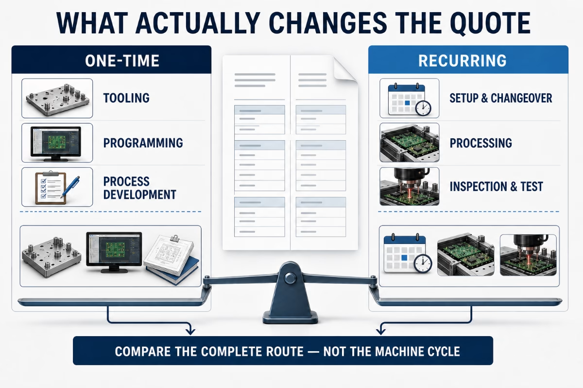
The unit price cannot be compared until the route assumptions are aligned. One quote may include tooling, programming, inspection, and process development. Another may leave them behind a single assembly line.
Separate one-time and recurring route costs before comparing wave and selective soldering.
| Quote driver | Wave-route question | Selective-route question | Why the buyer needs the answer |
| THT joint count and distribution | Which joints share the wave exposure? | Which joint groups require programmed access? | Shows whether the route matches the actual board |
| Bottom-side population and protected areas | What pallet/opening strategy is assumed? | What nozzle/path and protection assumptions are used? | Exposes access risk before production |
| Tooling, support, and setup | What is one-time, reusable, maintained, or replaced? | What fixtures, supports, programming, and setup are included? | Separates entry cost from recurring cost |
| Product mix and revisions | Which variants share the same tooling/process? | What must be reprogrammed or revalidated? | Prevents the first build price from hiding future change cost |
| Process development | What profile and trial work is included? | What local process development and trial work is included? | Shows whether engineering work is inside the quote |
| Inspection and test | Which checks and records are included? | Which checks and records are included? | Makes quality lines comparable instead of assumed |
| Repeat production | Which costs disappear, remain, or return? | Which costs disappear, remain, or return? | Clarifies what the next order will actually pay for |
Use the full PCB assembly quote checklist to align the wider package: fabrication, sourcing, assembly, inspection, test, quantity, and delivery. This article only adds the route-specific questions.
Send a Route-Ready RFQ, Not a BOM Alone
A BOM alone cannot support the soldering-route decision. Send synchronized design files and commercial requirements. The supplier can then review the same board you intend to buy.
| Input to send | What the supplier checks | Decision it affects | If missing |
| Gerber/ODB++ or approved fabrication data | Pads, mask, holes, board outline, and underside features | Basic route feasibility and tooling/access review | Review starts from assumptions |
| BOM with fitted/not-fitted status | THT population, connector types, special handling, and sourcing scope | Joint grouping and process planning | The quoted population may not match the build |
| Pick-and-place/CPL from the same revision | Top/bottom population and coordinates | Wave protection and selective access | Bottom-side conflicts can be missed |
| Assembly drawings | Polarity, special joints, protected areas, and process notes | Tooling, programming, sequence, and inspection | Supplier cannot see design intent |
| Fabrication drawing, stackup, and panel data | Construction, board support, panel handling, and thermal questions | Process-development scope | Route may change after engineering review |
| Quantity, repeat pattern, variants, and revision status | Tooling reuse, programming/setup, changeover, and revalidation | Route economics | Unit price can mislead |
| Material and process restrictions | Alloy/flux restrictions and prohibited exposures | Process compatibility | Quote may use the wrong process assumptions |
| Acceptance, inspection, test, and records | Required verification and documentation | Process approval and quote scope | Suppliers may price different quality packages |
Ask the supplier to return a decision, not another label
Request a route recommendation by joint group. It should identify six things: the proposed process, access/tooling assumptions, risk joints or features, the inspection response, one-time and recurring quote lines, and the conditions that would reopen the decision.
This is a deliverable the buyer should request. It is not a promise that OrinewPCB or any other supplier currently provides a named report in this exact format.
FAQ
These four questions should be answered as conditional checks, not universal rules.
Can selective soldering completely replace wave soldering?
No. Selective soldering can replace a wave step for some assemblies. Wave remains a valid candidate when the underside, tooling, process window, and production pattern support it. Keep both routes open until the supplier reviews the actual files. If neither process fits every joint group, use a hybrid or alternative route.
Is selective soldering always more expensive than wave soldering?
No. Compare the complete route rather than the machine cycle. Wave can carry pallet, setup, maintenance, and revision costs. Selective can carry programming, fixture/support, changeover, and local process-development costs. The lower-cost choice changes with joint distribution, product mix, repeat orders, inspection, and rework assumptions. Ask for one-time and recurring lines separately.
Does selective soldering guarantee better joint reliability?
No. A process name does not guarantee a reliable joint. Board design, materials, process control, acceptance requirements, inspection, test, and corrective action still determine whether the finished assembly is acceptable. Ask how the difficult joints will be verified instead of accepting a general reliability claim.
What is the difference between selective soldering and robotic soldering?
Selective soldering in this guide means a localized solder-wave or nozzle process aimed at programmed THT joint areas. The phrase “robotic soldering” does not identify enough of the proposed process. It cannot support a comparison on its own. Before comparing the two labels, ask the supplier to name five things: the heat source, solder delivery, access limits, process controls, and inspection.
Ready to Request a Board-Specific Soldering Review?
You provide the Gerber/ODB++, BOM, placement data, assembly drawings, panel information, quantity pattern, process restrictions, and acceptance/test requirements. The response you request should identify the proposed route by joint group, its access and tooling assumptions, risk features, inspection response, and separated one-time and recurring quote lines. This is a requested review scope, not a promise of a named OrinewPCB report or an approved production route.
About This Guide
This guide was compiled from the public sources linked near the claims they support. Supplier and operator material is attributed and used only for qualitative process boundaries, review variables, or user-question framing. IPC material is used only to describe document scope.
The 3-Gate Mixed-Assembly Route Check is an editorial framework, not an industry standard. The two route screens are illustrations, not first-party production cases. The article contains no claimed OrinewPCB process limits, equipment list, cost threshold, test result, certification, or guaranteed outcome.
References & Sources
- IPC Certifications — IPC
- Selective Wave Soldering
- Selective Soldering vs Wave Soldering: Advantages and Disadvantages
- Selective vs Wave Soldering vs Reflow Soldering/li>
- Talk to Me About Selective Soldering Machines
- PCB Assembly Quote Checklist — OrinewPCB
- SMT vs Through-Hole Components — OrinewPCB
Related Articles
- DIP and Wave Soldering in Modern PCBA — See where wave processing still fits in a through-hole assembly plan.
- Wave Soldering vs Reflow Soldering — Separate the SMT attachment decision from the remaining THT route.
- SMT vs Through-Hole Components — Compare component technologies before deciding how the mixed assembly should be processed.
- PCB Assembly Quote Checklist — Build the full fabrication, sourcing, assembly, inspection, and test RFQ package.

Get Quote Free