Rogers RO3035 Laminate: High-Frequency PCB
Rogers RO3035 high frequency circuit materials are PTFE composites filled with ceramic and designed for use in RF and commercial microwave applications. This guide covers everything you need to know about RO3035.
Get Your PCB Quote!
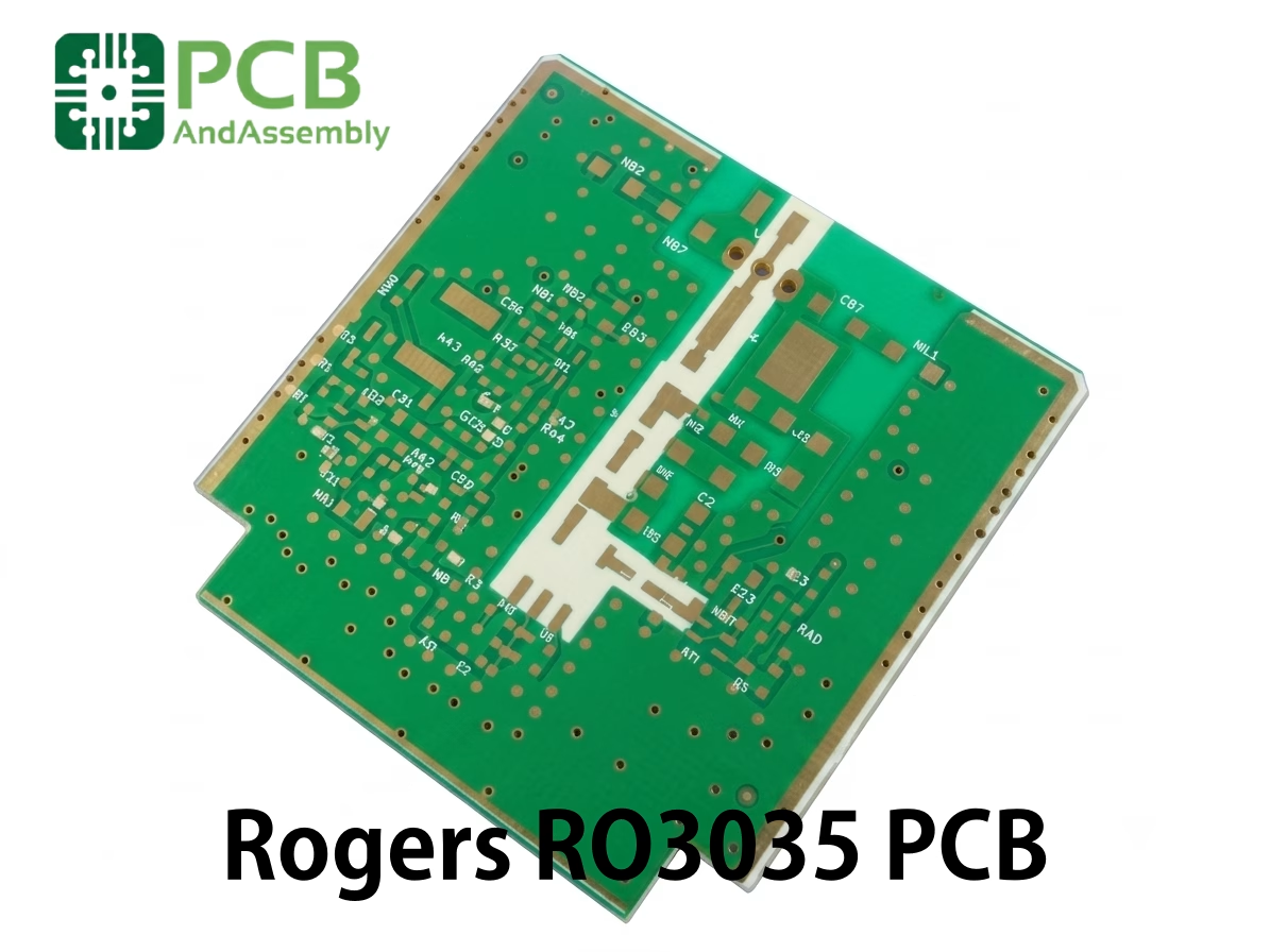
Table of Contents
- What is Rogers RO3035?
- RO3035 Electrical Properties
- RO3035 Mechanical and Thermal Properties
- Available Configurations
- RO3035 vs RO3003 vs RO3010: Choosing the Right RO3000 Material
- RO3035 vs FR-4: Why the Premium?
- RO3035 PCB Design Guidelines
- RO3035 Fabrication Guidelines
- RO3035 PCB Applications
- How to Order RO3035 PCB
- Useful Resources
- Frequently Asked Questions About Rogers RO3035 PCB
- Conclusion
Table of Contents
- What is Rogers RO3035?
- RO3035 Electrical Properties
- RO3035 Mechanical and Thermal Properties
- Available Configurations
- RO3035 vs RO3003 vs RO3010: Choosing the Right RO3000 Material
- RO3035 vs FR-4: Why the Premium?
- RO3035 PCB Design Guidelines
- RO3035 Fabrication Guidelines
- RO3035 PCB Applications
- How to Order RO3035 PCB
- Useful Resources
- Frequently Asked Questions About Rogers RO3035 PCB
- Conclusion
If you’re designing 5G antennas, power amplifiers, or millimeter-wave systems, you’ve likely discovered that FR-4 simply doesn’t work at these frequencies. The dielectric losses are excessive, impedance control becomes unreliable, and your carefully tuned circuit fails to perform. That’s where Rogers RO3035 PCB material comes in.
Rogers RO3035 is a ceramic-filled PTFE composite laminate with a dielectric constant of 3.50 ± 0.05 at 10 GHz — a carefully selected Dk that balances compact circuit dimensions with reasonable trace widths for impedance-controlled designs. It belongs to Rogers’ RO3000® series, a family of high-frequency laminates engineered specifically for applications where thermal stability, consistent electrical performance, and low loss are non-negotiable.
This guide covers everything you need to know about RO3035: the complete technical specifications, design guidelines, fabrication requirements, and real applications. Whether you’re specifying material for a 5G base station or troubleshooting an RF design, this article has the information you need.
Need PCB Manufacturing or Assembly?
Get a free quote within 24 hours. We specialize in prototype-to-production PCB/PCBA for hardware teams worldwide.
What is Rogers RO3035?
Rogers RO3035 is a ceramic-filled PTFE (polytetrafluoroethylene) composite laminate designed for high-frequency circuit applications. Unlike woven-glass reinforced materials, the ceramic filler in RO3035 provides a homogeneous dielectric constant throughout the panel, with no resin-rich or glass-rich areas that cause Dk variation.
The RO3000 series was developed by Rogers Corporation to address the need for materials with Dk values between the ultra-low Dk of the RT/Duroid series (2.20-2.33) and the high-Dk ceramic materials used for circuit miniaturization. RO3035, with its 3.50 Dk, sits in the middle of this series alongside RO3003 (Dk 3.0) and RO3006 (Dk 6.15).
Why Engineers Choose RO3035
Three characteristics drive the selection of RO3035 over other high-frequency laminates.
Dielectric Constant Stability: The ±0.05 Dk tolerance is remarkably tight for a ceramic-filled material. When you’re designing a bandpass filter with tight passband requirements at 28 GHz, that consistency across panels and over temperature is what separates a production-ready design from a tuning nightmare.
Thermal Management: With a thermal conductivity of 0.50 W/m/K, RO3035 dissipates heat more than twice as effectively as standard PTFE materials (typically 0.20-0.25 W/m/K). This matters enormously in power amplifier designs where junction temperatures directly impact reliability and output power.
Low Z-axis CTE: The Z-axis coefficient of thermal expansion measures just 24 ppm/°C — closely matching copper’s 17 ppm/°C. This reduces stress on plated through-holes during thermal cycling, a critical reliability factor for automotive and aerospace applications.
RO3035 Electrical Properties
The electrical specifications define what frequencies and applications the material supports. Here are the published values from the Rogers datasheet.
Key Electrical Specifications
| Property | Value | Test Condition | Test Method |
| Dielectric Constant (Dk) | 3.50 ± 0.05 | 10 GHz, 23°C | IPC-TM-650 2.5.5.5 |
| Dissipation Factor (Df) | 0.0015 | 10 GHz, 23°C | IPC-TM-650 2.5.5.5 |
| Design Dk | 3.50 | 10 GHz | Process Specification |
| Thermal Coefficient of Dk | -45 ppm/°C | -50°C to 150°C | — |
| Volume Resistivity | 1 × 10⁷ MΩ·cm | — | IPC-TM-650 2.5.17.1 |
| Surface Resistivity | 1 × 10⁷ MΩ | — | IPC-TM-650 2.5.17.1 |
The dielectric constant of 3.50 represents a practical sweet spot. At this Dk, a 50Ω microstrip line on 0.020″ (20 mil) substrate yields a trace width around 40 mils — wide enough for reliable etching but compact enough for moderate-density designs. Higher Dk materials shrink trace widths further, which can introduce manufacturing challenges.
The dissipation factor of 0.0015 at 10 GHz places RO3035 among the lower-loss ceramic-filled PTFE materials. While not as low as pure PTFE materials like RT/Duroid 5880 (Df 0.0009), it represents excellent performance for a filled system and supports applications well into the millimeter-wave range.
Frequency Stability
The thermal coefficient of Dk at -45 ppm/°C means the dielectric constant changes by only 45 parts per million for every degree Celsius of temperature change. Over a typical -40°C to +85°C operating range, that translates to a Dk shift of approximately ±0.006 — negligible for most applications. This stability is critical for automotive radar systems and outdoor 5G equipment that must perform reliably across extreme temperature swings.
RO3035 Mechanical and Thermal Properties
Electrical performance is only half the story. A PCB material must survive fabrication, assembly, and years of field operation.
Mechanical Specifications
| Property | Value | Direction | Test Method |
| Tensile Modulus | — | X | — |
| Flexural Modulus | 1,400 MPa | — | ASTM D790 |
| Specific Gravity | 2.1 | — | ASTM D792 |
| Copper Peel Strength | 8.8 N/mm | — | IPC-TM-650 2.4.8 |
| Water Absorption | 0.04% | — | IPC-TM-650 2.6.2.1 |
Thermal Specifications
| Property | Value | Test Method |
| CTE (X-axis) | 17 ppm/°C | ASTM E831 |
| CTE (Y-axis) | 17 ppm/°C | ASTM E831 |
| CTE (Z-axis) | 24 ppm/°C | ASTM E831 |
| Thermal Conductivity | 0.50 W/m/K | ASTM C518 |
| Decomposition Temperature (Td) | >500°C | TGA |
| Flammability Rating | UL 94 V-0 | UL Standard |
The in-plane CTE of 17 ppm/°C matches copper almost perfectly. This alignment prevents board warpage during thermal cycling and improves the reliability of surface-mounted components. The Z-axis CTE of 24 ppm/°C, while higher than copper, is significantly lower than many pure PTFE materials, which can exceed 200 ppm/°C in the Z-axis.
Water absorption of 0.04% is exceptionally low. In humid environments or outdoor installations, absorbed moisture can shift the dielectric constant and degrade RF performance. RO3035’s resistance to moisture absorption makes it suitable for base station antennas and outdoor radar systems that must maintain consistent performance regardless of weather conditions.
Available Configurations
Rogers supplies RO3035 in multiple thicknesses and copper cladding options to accommodate different design requirements.
Standard Dielectric Thicknesses
| Thickness (inch) | Thickness (mm) | Tolerance |
| 0.005 | 0.127 | ±0.0005″ |
| 0.010 | 0.254 | ±0.0007″ |
| 0.020 | 0.508 | ±0.0015″ |
| 0.030 | 0.762 | ±0.0020″ |
| 0.060 | 1.524 | ±0.0030″ |
Copper Cladding Options
Electrodeposited (ED) Copper: Available in 1/2 oz (18 μm), 1 oz (35 μm), and 2 oz (70 μm) weights. ED copper provides good adhesion and is suitable for most applications. This is the standard option for prototype and production runs.
Rolled Copper Foil: Available in 1/2 oz and 1 oz for applications where lower conductor loss is critical. Rolled copper has a smoother surface finish that reduces skin-effect losses at higher frequencies — particularly important above 20 GHz.
Reverse Treated ED Copper: Provides enhanced adhesion to the ceramic-filled PTFE substrate while maintaining good electrical performance. This option is preferred for multilayer constructions where copper-to-prepreg adhesion is critical.
Standard Panel Sizes
Panels are typically available in sizes up to 24″ × 18″ (610 mm × 457 mm). Larger panel sizes may be available on special order through authorized distributors.
RO3035 vs RO3003 vs RO3010: Choosing the Right RO3000 Material
The RO3000 series offers several dielectric constant options, each optimized for different applications. Understanding the differences helps you select the right material for your design.
Comparison Table
| Property | RO3003 | RO3035 | RO3010 |
| Dielectric Constant (Dk) | 3.00 ± 0.04 | 3.50 ± 0.05 | 10.2 ± 0.30 |
| Dissipation Factor (Df) | 0.0013 | 0.0015 | 0.0035 |
| Thermal Conductivity (W/m/K) | 0.50 | 0.50 | 0.83 |
| Z-axis CTE (ppm/°C) | 25 | 24 | 23 |
| Water Absorption (%) | 0.04 | 0.04 | 0.05 |
| Relative Cost | Baseline | Slightly Higher | Higher |
When to Choose RO3035
Select RO3035 when you need a Dk of 3.50 for circuit miniaturization but still want manageable trace widths for 50Ω impedance. It’s the go-to choice for patch antennas, power dividers, and matching networks in the 3-30 GHz range. The thermal conductivity of 0.50 W/m/K makes it particularly suitable for power amplifier circuits where heat dissipation matters.
When to Choose RO3003
Choose RO3003 (Dk 3.0) when wider trace widths are acceptable and you want the lowest possible Dk variation (±0.04). The slightly lower Dk reduces signal delay per unit length, which can be beneficial in phase-sensitive arrays.
When to Choose RO3010
RO3010 (Dk 10.2) is the choice when maximum circuit miniaturization is required. The high dielectric constant shrinks wavelength significantly, enabling compact filter and antenna designs. However, the narrow trace widths required for 50Ω impedance can approach manufacturing limits, and the higher Df of 0.0035 means more insertion loss.
RO3035 vs FR-4: Why the Premium?
For engineers accustomed to FR-4 pricing, the cost of RO3035 requires justification. Here’s what the performance difference looks like in numbers.
Performance Comparison
| Property | Rogers RO3035 | Standard FR-4 |
| Dielectric Constant | 3.50 ± 0.05 | 4.2-4.8 ± 10% |
| Dissipation Factor | 0.0015 | 0.02-0.025 |
| Dk Stability vs Frequency | Excellent | Poor above 1 GHz |
| Thermal Conductivity (W/m/K) | 0.50 | 0.25-0.35 |
| Water Absorption | 0.04% | 0.1-0.3% |
| Maximum Usable Frequency | 40+ GHz | ~2 GHz |
| Dk Tolerance | ±1.4% | ±10% |
At 3.5 GHz (a common 5G frequency), FR-4’s dissipation factor is roughly 15 times higher than RO3035. This translates directly to insertion loss. In a typical 4-stage power divider network, the accumulated loss difference between RO3035 and FR-4 can exceed 2 dB — enough to reduce a 1W output amplifier to 0.63W effective output power.
For applications below 1 GHz where insertion loss is not critical, FR-4 remains a sensible and cost-effective choice. Above that frequency, and especially in any application where transmitted power, received signal strength, or thermal management matters, the premium for RO3035 is justified by measurable performance gains.
RO3035 PCB Design Guidelines
Designing with RO3035 requires understanding how its ceramic-filled PTFE construction affects layout decisions.
Impedance Control Considerations
The Dk of 3.50 results in moderate trace widths for standard impedances. For 50Ω microstrip on 0.020″ (20 mil) substrate, expect trace widths around 40-42 mils. On 0.010″ (10 mil) substrate, the same impedance yields approximately 20-22 mil traces — both dimensions that are straightforward to manufacture.
Design Tip: Use the Design Dk of 3.50, not the relative permittivity from casual measurements. Rogers publishes Design Dk values calibrated for common transmission line models (microstrip, stripline). Using the wrong Dk value in your field solver can introduce impedance errors of 2-4%.
Stackup Recommendations
For multilayer RO3035 constructions:
- Hybrid stackups: RO3035 combines well with RO4450F or RO4450T bondply for multilayer lamination
- Copper balance: Maintain symmetric copper distribution across layers to minimize warpage during lamination
- Grain direction: Align grain direction between laminate sheets in multilayer constructions
- Layer count: 2-6 layer designs are practical; higher layer counts require careful thermal management during lamination
Via Design for Plated Through-Holes
The Z-axis CTE of 24 ppm/°C is close to but slightly higher than copper’s 17 ppm/°C. In practice:
- Aspect ratio: Keep aspect ratios below 10:1 for reliable plating
- Annular rings: Minimum 5 mils (0.127 mm) recommended
- Plating thickness: Specify 1.0-1.2 mils (25-30 μm) minimum copper in holes
- Thermal relief: Use thermal relief pads on power and ground connections to manage heat distribution during soldering
Thermal Management in Layout
The 0.50 W/m/K thermal conductivity, while good for PTFE materials, is still lower than aluminum-based substrates. For high-power designs:
- Use multiple thermal vias under heat-generating components
- Consider copper coin inserts for concentrated heat sources
- Distribute power across wider traces where current density is high
- Plan for adequate copper thickness (2 oz or more) for power paths
RO3035 Fabrication Guidelines
Fabricating RO3035 requires modifications to standard FR-4 processing but is well within the capabilities of any PCB manufacturer experienced with high-frequency materials.
Drilling Parameters
Ceramic-filled PTFE drills differently than woven-glass FR-4:
- Drill material: Carbide with 130° included lip angle
- Surface speed: 200-300 SFM (60-90 m/min)
- Chip load: 0.001-0.002″ per revolution
- Stack height: Maximum 0.240″ (6.1 mm)
- Drill quality: New or re-sharpened drills strongly recommended
Critical Warning: Ceramic filler particles accelerate drill wear significantly compared to FR-4. Monitor drill life carefully — a worn drill produces rough hole walls and can cause plating failures. Typical drill life is 500-1000 hits for RO3035 compared to 2000+ for FR-4.
Plasma Desmear
PTFE-based materials require plasma desmear before electroless copper plating. Standard FR-4 permanganate desmear is insufficient for RO3035.
- Process: Oxygen/nitrogen or CF₄/O₂ plasma
- Purpose: Removes resin smear from drilled hole walls
- Result: Clean copper-to-copper connection in through-holes
Surface Treatment for Plating
Ceramic-filled PTFE does not naturally accept electroless copper deposition. Surface activation is mandatory:
- Sodium etching: Creates a chemically reactive surface for electroless copper. Products like Tetra-Etch are industry standards
- Plasma treatment: Preferred for environmentally sensitive manufacturing processes. Uses H₂/N₂ or NH₃ gas plasma
- Direct metallization: Some fabricators use palladium-based direct metallization processes that work with plasma-treated PTFE surfaces
Compatible Surface Finishes
RO3035 supports all standard surface finishes:
- ENIG(Electroless Nickel Immersion Gold): Best for high-frequency applications due to smooth surface finish. Preferred for millimeter-wave designs
- Immersion Silver: Excellent RF performance at moderate cost
- HASL(Hot Air Solder Leveling): Available but not recommended for designs above 10 GHz due to surface roughness
- OSP (Organic Solderability Preservative): Cost-effective for prototype runs
- Immersion Tin: Suitable for solderability with good planar surface
For designs operating above 10 GHz, ENIG or immersion silver provide the best RF performance due to their smooth surface profiles.
Lead-Free Assembly Compatibility
RO3035’s decomposition temperature exceeds 500°C, well above lead-free soldering temperatures (260°C peak). The material is fully compatible with RoHS-compliant assembly processes. No special handling is required beyond standard high-frequency laminate practices.
RO3035 PCB Applications
The combination of moderate Dk, low loss, and good thermal conductivity makes RO3035 suitable for a wide range of demanding applications.
5G and Cellular Infrastructure
Massive MIMO Antenna Arrays: 5G base stations use antenna arrays with 64, 128, or more elements. RO3035’s consistent Dk across panels ensures predictable phase response across the array, which is critical for beamforming accuracy.
Sub-6 GHz Power Amplifiers: The thermal conductivity of 0.50 W/m/K helps dissipate heat from GaN and GaAs power amplifiers used in 5G transmitters. Combined with the low insertion loss, overall system efficiency improves measurably.
Small Cell Backhaul: Point-to-point links operating at 18-42 GHz benefit from RO3035’s stable electrical performance and low loss at millimeter-wave frequencies.
Automotive Radar
77 GHz Radar Systems: Automotive radar modules operating at 76-81 GHz require materials with tightly controlled Dk and low loss. RO3035 supports these frequencies with acceptable performance, though some designers may prefer specialized automotive radar laminates for volume production.
24 GHz Short-Range Radar: For blind-spot detection and cross-traffic alert systems operating at 24 GHz, RO3035 provides excellent performance at a lower cost than ultra-low-loss alternatives.
Aerospace and Defense
Phased Array Radar: Airborne and ground-based phased array systems benefit from RO3035’s stable performance across temperature and frequency. The low Z-axis CTE improves reliability in thermal cycling environments.
Satellite Communications: Antenna feed networks and RF distribution systems in satellite terminals use RO3035 for its consistent electrical properties and resistance to moisture absorption.
Test and Measurement Equipment
RF Probe Cards: Test probes for wafer-level RF testing require materials with predictable Dk and low loss. RO3035’s tight Dk tolerance makes it suitable for precise impedance reference standards.
Calibration Substrates: The ±0.05 Dk tolerance enables accurate calibration standards for vector network analyzers and impedance test equipment.
How to Order RO3035 PCB
When specifying RO3035 for your project, include these parameters:
- Material: Rogers RO3035 per specification
- Dielectric thicknessand tolerance
- Copper type: ED, rolled, or reverse treated
- Copper weight: 1/2 oz, 1 oz, or 2 oz
- Panel sizerequirements
- Panel quantity
- Any special processing(routed contours, slotting, etc.)
At PCBAndAssembly we fabricate high-frequency PCBs using Rogers materials including RO3035, RO3003, RT/Duroid 5870, and more. Our engineering team can help you select the right laminate and stackup for your RF design.
Typical Lead Times and Costs
Lead times for production quantities through authorized distributors typically run 4-6 weeks. Prototype quantities are often available from stock.
Useful Resources
Here are authoritative sources for RO3035 technical information:
Rogers Corporation Official Resources:
- RO3000 Series Laminate Data Sheet (Publication #92-130)
- High Frequency Luminate Fabrication Guidelines
- Rogers MWI-2020 Impedance Calculator
Design Tools:
- Rogers MWI Impedance Calculator — free download from rogerscorp.com
- Saturn PCB Design Toolkit — trace impedance, via current, and thermal calculations
- Polar Instruments Si9000 — field solver for controlled impedance design
Frequently Asked Questions About Rogers RO3035 PCB
What is the maximum operating frequency for RO3035 PCB?
RO3035 performs well through Ka-band (26-40 GHz) and remains usable into V-band (40-75 GHz) for many applications. The dissipation factor of 0.0015 at 10 GHz maintains acceptable losses up to 40+ GHz, though conductor losses become the dominant loss mechanism above 30 GHz as the skin effect concentrates current at the trace surface. For designs above 50 GHz, consider rolled copper foil to minimize conductor losses.
How does RO3035 compare to RO4350B for RF applications?
RO3035 and RO4350B serve different design spaces. RO4350B is a woven-glass reinforced hydrocarbon/ceramic material with Dk of 3.48, very similar to RO3035’s 3.50. However, RO4350B has a higher dissipation factor (0.0037 vs 0.0015), roughly 2.5× the loss of RO3035. RO4350B costs less and processes more like standard FR-4 (better for high-volume production). Choose RO3035 when insertion loss is critical; choose RO4350B when cost and standard processing matter more.
Can RO3035 be used for multilayer PCB construction?
Yes. RO3035 supports multilayer construction using Rogers RO4450F or RO4450T bondply materials. Fusion bonding (direct lamination without adhesive) is also possible. For hybrid constructions combining RO3035 with other materials, discuss the stackup with your fabricator to ensure compatible processing parameters. Six-layer designs using RO3035 cores with RO4450F prepreg are common in 5G antenna designs.
What surface finish is best for RO3035 millimeter-wave designs?
ENIG (Electroless Nickel Immersion Gold) is the preferred surface finish for millimeter-wave applications due to its smooth surface profile. At frequencies above 20 GHz, surface roughness becomes a significant contributor to conductor loss. ENIG provides a flat surface that minimizes this effect. Immersion silver is a good second choice. Avoid HASL for designs above 10 GHz due to the uneven surface profile created by the hot air leveling process.
Does RO3035 require special drilling compared to FR-4?
Yes. The ceramic filler in RO3035 accelerates drill wear significantly compared to FR-4. Use carbide drills and expect shorter drill life (500-1000 hits vs 2000+ for FR-4). Plasma desmear is mandatory after drilling to remove PTFE smear from hole walls before plating. Standard FR-4 permanganate desmear is not effective on PTFE-based materials.
Is RO3035 suitable for high-power amplifier designs?
RO3035’s thermal conductivity of 0.50 W/m/K makes it one of the better choices among PTFE-based laminates for power applications. It dissipates heat more than twice as effectively as standard PTFE materials. Combined with appropriate thermal via arrays and copper coin inserts where needed, RO3035 supports power levels up to moderate RF power ranges (10-100 W depending on frequency and circuit topology). For very high power applications, consider aluminum-backed RO3035 or ceramic substrates.
Conclusion
Rogers RO3035 PCB material fills a critical gap in the high-frequency laminate market. With a Dk of 3.50, it enables circuit miniaturization beyond what Dk 2.2-3.0 materials allow, while maintaining practical trace widths for 50Ω impedance designs. The thermal conductivity of 0.50 W/m/K, low Z-axis CTE matching copper, and exceptionally low water absorption make it suitable for demanding applications from 5G infrastructure to automotive radar.
The material’s tight Dk tolerance (±0.05) and consistent panel-to-panel performance give designers confidence that simulation will match production reality — a requirement that becomes increasingly critical as operating frequencies climb into the millimeter-wave range.
Next steps: If you’re evaluating RO3035 for your next design, contact your Rogers distributor for current pricing and availability. For prototype quantities, most authorized distributors maintain stock of standard thicknesses and copper configurations.

Get Quote Free