PCB Manufacturing and Assembly: Know the Step-By-Step Process
PCB Manufacturing and Assembly: The Complete Step-by-Step Process Meta Description: From Gerber files to a tested board in 22 steps. This guide walks through every fabrication and assembly stage, with failure modes, key parameters, and decisions that affect cost and lead time.
Get Your PCB Quote!
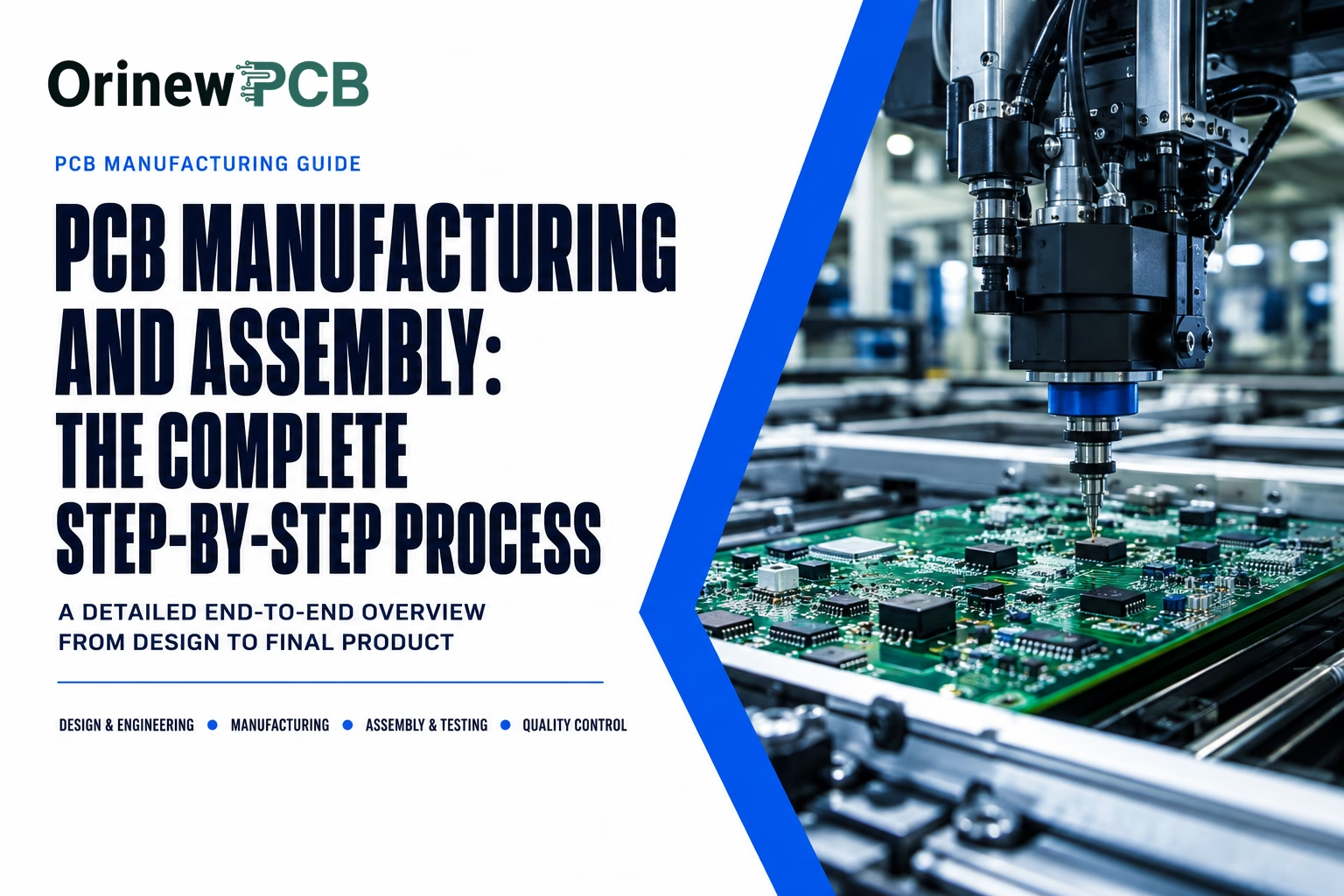
Table of Contents
- Quick Specs
- The two-lane map: PCB fabrication vs assembly and where the handoff happens
- The 6-file input checklist: What the fab and the assembler need from you
- The inner-layer line: Imaging, etching, and the tolerances that decide yield
- The lamination gate: How 4+ layers become one board
- The drilling and plating worksheet: Why via barrel thickness is the reliability bottleneck
- The solder mask and surface finish crosswalk: What your pads are covered with
- The quality-checkpoint index: From bare board to functional test
- The assembly line: 8 steps from solder paste to functional test — and how mixed boards change the sequence
- The schedule and cost ladder: Which process choices move your timeline and budget
- FAQ
- References
- Related articles
Table of Contents
- Quick Specs
- The two-lane map: PCB fabrication vs assembly and where the handoff happens
- The 6-file input checklist: What the fab and the assembler need from you
- The inner-layer line: Imaging, etching, and the tolerances that decide yield
- The lamination gate: How 4+ layers become one board
- The drilling and plating worksheet: Why via barrel thickness is the reliability bottleneck
- The solder mask and surface finish crosswalk: What your pads are covered with
- The quality-checkpoint index: From bare board to functional test
- The assembly line: 8 steps from solder paste to functional test — and how mixed boards change the sequence
- The schedule and cost ladder: Which process choices move your timeline and budget
- FAQ
- References
- Related articles
Quick Specs
| Parameter | Value |
| Fabrication stages (bare board) | 14 steps (imaging → routing) |
| Assembly stages (populated board) | 8 steps (solder paste → functional test) |
| Standard trace/space (standard process) | 4 mil / 4 mil (0.10mm) |
| Minimum via barrel plating (IPC-6012F Class 2) | ≥20 µm average, ≥18 µm any point |
| Drill aspect ratio (standard) | 8:1 to 10:1 |
| SMT share of modern electronics assembly | ~90% |
| Prototype lead time (2–4 layer) | 24–72 hours quick-turn; 5–10 days standard |
| Governing standards | IPC-6012F (fab), IPC-A-610J / J-STD-001J (assembly), IPC-2221C (design) |
PCB manufacturing and assembly is the two-stage process that turns Gerber files into a working, tested circuit board — and most of the engineering risk is hidden in that simple sentence. Stage one, fabrication, converts digital design files into a bare board: copper traces, laminate, vias, solder mask, surface finish. Stage two, assembly, places components onto that board and solders them into place. Different process flows. Different IPC standard families. Different failure modes. Yet buyers routinely treat the two as one interchangeable service.
In one paragraph: fabrication builds the bare board (imaging → etching → lamination → drilling → plating → surface finish → electrical test), governed by IPC-6012F. Assembly mounts components (solder paste → placement → reflow → through-hole → inspection → test), governed by IPC-A-610J and J-STD-001J. The handoff between the two is the bare board itself — and every decision you make in stage one either helps or hurts stage two.
Key Takeaways
- Fabrication and assembly are governed by different IPC standard families. Saying “IPC certified” without naming the specific standard (IPC-6012F for fab, IPC-A-610J for assembly) is an expensive but common mistake.
- The minimum via barrel plating is 20 µm average under IPC-6012F Class 2 — below that, thermal cycling will crack the barrel. This is verifiable only by microsection, not by electrical test.
- SMT accounts for roughly 90% of component placements in modern electronics (vendor-reported). The remaining through-hole parts need a separate soldering step that can reheat the entire board.
- Surface finish choice (ENIG vs HASL vs OSP) directly affects assembly yield for fine-pitch components. Specify it at quote time — switching mid-order adds 2–3 days and a plating-line premium.
- A board that survives AOI after reflow is a board that was printed, placed, and profiled correctly three steps earlier. Most assembly defects trace back to the steps before soldering.
The two-lane map: PCB fabrication vs assembly and where the handoff happens
The confusion starts with vocabulary. “PCB manufacturing” gets used to mean both fabrication and assembly, even within the same company. Here’s what each stage actually produces and who governs it.
| Dimension | Fabrication (bare board) | Assembly (populated board) |
| Output | Bare board with copper traces, vias, mask, finish | Board with all components soldered and tested |
| Governing standard | IPC-6012F (bare-board qualification) | IPC-A-610J (workmanship) + J-STD-001J (soldering) |
| Design standard | IPC-2221C (design guidelines) | IPC-A-610J (acceptance) |
| Key process | Imaging, etching, lamination, drilling, plating | Solder paste printing, pick-and-place, reflow |
| Typical defects | Acid traps, plating voids, mask misregistration | Solder bridges, tombstoning, BGA voids |
| Quality verification | Electrical test + AOI + microsection | AOI + X-ray + ICT/FCT |
| When it fails | Board won’t function (open/short) | Board assembles but fails in field (cold joint, cracked barrel) |
Two boards can leave a fabrication line looking identical — different layer registration, plating thickness, surface finish quality. The differences show up during assembly, or in the field. The fab doesn’t know how the board will be assembled. The assembler doesn’t control how it was fabricated. Both need to do their job right.
“Asking for ‘IPC certification’ without specifying the standard is an expensive but common mistake. The fabrication line works to IPC-6012F, the assembly line to IPC-A-610J — different documents, different acceptance criteria.”
— OrinewPCB DFM Engineering Team
Decision rule: if your purchase order says “IPC certified” without naming the specific standard, add the number before the order goes out. IPC-6012F for bare boards, IPC-A-610J and J-STD-001J for assembly. The wrong standard on the PO doesn’t just create confusion — it can result in the wrong inspection criteria being applied to your board.
The 6-file input checklist: What the fab and the assembler need from you
Delays and rework. Almost always trace back to one thing: an incomplete or incorrect file package. Every fab and every assembler will tell you the same — the files you send determine the board you get.
| File | What it gates | Most common mistake |
| Gerber / ODB++ / IPC-2581 | Copper pattern, mask, silkscreen, drill | Missing drill file (.drl) — fab can’t drill without it |
| Drill file (Excellon .drl) | Hole locations and sizes | Metric vs imperial mismatch (0.25mm ≠ 0.025″) |
| BOM (bill of materials) | Component sourcing and placement | Listing only resistance values without manufacturer part numbers |
| Centroid / pick-and-place file | Component X/Y position and rotation | Wrong origin point — components placed mirrored or off-board |
| Stackup drawing | Layer build-up, materials, copper weights | Not specifying prepreg thickness — fab picks a default that may not match your impedance target |
| Assembly drawing | Component reference designators, polarity, notes | Missing polarity markings on diodes and electrolytic caps |
The fab uses Gerber, drill, and stackup. The assembler uses BOM, centroid, and assembly drawing. Most buyers send one package to both — which works, as long as the BOM includes manufacturer part numbers. A BOM that says “100nF, 0402” without a part number forces the assembler to guess. Guesses create substitution risks.
The fab runs a DFM (Design for Manufacturability) check on your Gerber and drill files before production starts. This is not optional. It’s the fab’s quality gate. A good DFM review catches acid traps, insufficient annular ring, trace-to-pad clearances below capability, drill-to-copper violations. If you get a DFM report back, read it. Every flag on that report is a defect the fab caught before it became a scrapped panel.
Decision rule: send the same six files to both your fab and your assembler. Include manufacturer part numbers on the BOM and verify the drill file is included with the Gerber set. This single preparation step eliminates more rework than any other.
The inner-layer line: Imaging, etching, and the tolerances that decide yield
Inner-layer processing. Where etch variation kills your yield — and the step most buyers never see.
| Step | What happens | Key parameter | What can go wrong |
| 1. LDI imaging | Laser direct imaging transfers circuit pattern to photoresist on copper-clad laminate | Exposure energy, focus ±2 µm | Trace width variation, broken signal lines |
| 2. Developing | Unexposed photoresist washes away, exposing copper | Development time and chemistry concentration | Over-development thins traces; under-development leaves resist residue |
| 3. Etching | Chemical bath removes exposed copper | Etch factor (vertical-to-lateral ratio) | Over-etching thins traces below spec; under-etching leaves copper shorts |
| 4. Stripping | Remaining photoresist is removed | Stripper chemistry and temperature | Residual resist blocks subsequent lamination adhesion |
| 5. AOI inspection | Automated optical inspection compares pattern to Gerber data | Inspection resolution, defect classification | False calls slow line; missed defects pass to lamination |
The critical number: trace width. Standard process minimum is 4 mil / 4 mil (0.10mm trace, 0.10mm space) — but that’s the fab’s nominal capability, not the guaranteed output. A design at exactly 4 mil on a 4 mil line has zero margin. Production etch rates shift trace width by 10–20% depending on chemistry age, panel loading, conveyor speed.
Here’s where buyers get surprised. A prototype board with 4 mil traces measured 3.8 mil at worst — within tolerance. Same Gerber set, production line, tighter etch factor control: 3.2 mil on some features. Board failed electrical test.
“We’ve seen customers submit designs with 4 mil trace/space carried over from a prototype run, confident it would work at production scale. On a production line, etch variation routinely pushes trace width 10–20% below nominal. Design with margin.”
— OrinewPCB CAM Engineering Team
Etch factor matters more than minimum trace width. Typical production etch factor: 3:1 to 4:1 (vertical etch depth to lateral undercut). On 1 oz (35 µm) copper, a 3:1 factor means roughly 12 µm lateral undercut per side. For a 4 mil (100 µm) trace, that’s 24 µm eaten from both sides — leaving a 76 µm actual trace. If the design specified exactly 4 mil, you’re already below spec.
Design with 25% margin above the fab’s minimum. A 5 mil design on a 4 mil capability line has room for variation.
Decision rule: design with 25% margin above the fab’s minimum trace/space. A 4 mil design on a 4 mil capability line has no room for etch variation — it will pass prototype but can fail production.
The lamination gate: How 4+ layers become one board
For multilayer boards, lamination fuses individual inner-layer pairs into a single board under heat and pressure. Most common point of yield loss in multilayer fabrication.
| Stage | What happens | What can go wrong |
| Oxide/brown treatment | Inner-layer copper is chemically roughened to improve adhesion to prepreg | Insufficient roughness → delamination under thermal stress |
| Layup | Prepreg, core, and copper foil are stacked per the stackup drawing | Wrong prepreg thickness → impedance out of spec; asymmetric stackup → warp |
| Lamination press | Heat (180–200°C), pressure (250–400 psi), and vacuum fuse layers | Resin starvation (voids), resin flow excess (filling features), registration shift |
| Cool-down | Controlled cooling to prevent thermal stress | Too-rapid cooling → internal stress → warp in later processing |
The lamination press does three things at once: melts prepreg resin, flows it to fill gaps between copper features, bonds everything into a monolithic structure. Press profile — temperature ramp, hold time, pressure, vacuum level — is the fab’s most closely guarded parameter. It determines whether your board delaminates in the field.
Boards with 6+ layers may need lamination twice: once for inner layers, again after outer-layer processing. Each cycle adds roughly 1–2 days to lead time and 30–50% to fabrication cost (directional — varies by layer count and fab).
Stackup symmetry is not optional. Same materials and thicknesses above and below the center line — equal thermal expansion on both sides. An asymmetric stackup (say, 2 mil prepreg on one side, 4 mil on the other) creates differential expansion during reflow. The board warps.
IPC-6012F specifies bow and twist limits of ≤0.75% for surface-mount boards. A warped board fails SMT placement. Stencil doesn’t contact pads evenly. Reflow produces inconsistent solder joints.
Decision rule: keep your stackup symmetrical and specify it explicitly in your stackup drawing. A board that warps in lamination fails in assembly reflow, and no test fixture fixes a warped board.
The drilling and plating worksheet: Why via barrel thickness is the reliability bottleneck
Drilling creates the holes. Plating makes them conductive. Together they form the most reliability-critical feature on a multilayer board: the plated through-hole.
| Parameter | Standard value | What happens if out of spec |
| Minimum mechanical drill diameter | ~0.2 mm (8 mil) standard; ~0.125 mm (5 mil) advanced | Below 0.2 mm, drill breakage rate rises sharply; below 0.125 mm, micro-drill or laser required |
| Drill aspect ratio | 8:1 to 10:1 standard; 12:1 to 15:1 advanced | Above 10:1, plating uniformity drops — thin spots create crack initiation sites |
| Via barrel plating (IPC-6012F Class 2) | ≥20 µm average, ≥18 µm any point | Thin plating → barrel cracking under thermal cycling → intermittent open in field |
| Via barrel plating (IPC-6012F Class 3) | ≥25 µm average, ≥20 µm any point | Same failure, tighter threshold — Class 3 boards cannot tolerate thin plating |
| Annular ring (Class 2) | ≥50 µm (2 mil) | Reduced ring → breakout at barrel → unreliable connection |
| Annular ring (Class 3) | No reduction allowed — full ring required | Any breakout is a reject |
Drill accuracy matters because the hole must land on the copper pad with enough annular ring left after wander. A typical CNC drill hits within ±0.05 mm (2 mil) — center-to-center. Add drill wander (bit deflecting as it enters the material) and you lose another 0.02–0.03 mm. A 0.3 mm pad with a 0.2 mm drill leaves 0.05 mm (50 µm) annular ring — right at the IPC-6012F Class 2 minimum.
The plating process fills the drilled hole with copper. Chemistry must penetrate a deep, narrow cylinder and deposit uniform copper on every surface. In a 1.6 mm board with 0.3 mm vias (5.3:1), solution circulates well. Push to 10:1 (1.6 mm board, 0.16 mm vias) and flow in the barrel gets restricted — center gets thinner plating than entry points. Above 12:1, standard chemistry often can’t guarantee 20 µm. Fabs switch to pulsed plating (alternating current on/off cycles to refresh solution in the barrel).
Divide board thickness by drill diameter.
- 1.6 mm board, 0.3 mm vias = 5.3:1 (comfortable)
- 2.4 mm board, 0.2 mm vias = 12:1 (requires pulsed plating)
- 3.2 mm board, 0.15 mm vias = 21:1 (borderline — verify with your fab before committing)
IPC-6012F does not set a maximum aspect ratio. The limit is what the fab’s plating line can reliably plate to 20 µm.
Decision rule: if your via aspect ratio exceeds 10:1, ask your fabricator directly whether they pulse-plate. Standard chemistry stops guaranteeing barrel coverage above that point.
The solder mask and surface finish crosswalk: What your pads are covered with
Solder mask — the green coating — is a liquid photoimageable (LPI) polymer coated over the entire board, then selectively exposed and developed to leave openings over pads and vias. Why green? Best contrast for AOI systems. Before AOI existed, least eye-straining for human inspectors. Red, blue, black, white exist for aesthetics or thermal needs, but green is the default.
Surface finish is the thin metal layer on exposed copper pads. Prevents oxidation. Enables soldering. The choice directly affects assembly yield for fine-pitch components.
| Finish | Cost (relative to HASL) | Shelf life | Best for | Watch out for |
| HASL (lead-free) | Baseline | 12+ months | Through-hole, standard SMT, low-cost | Uneven pad surface — causes tilt on fine-pitch components |
| ENIG | +15–25% (vendor-reported) | 12+ months | Fine-pitch BGA, QFN, flat-pad components | “Black pad” risk if nickel plating process is poorly controlled |
| OSP | –10–20% vs HASL | 6–12 months | High-volume single-reflow designs | Degrades with multiple reflow passes; short shelf life |
| Immersion tin | Comparable to ENIG | 6–12 months | Press-fit connectors, fine-pitch | Tin whisker risk; limited shelf life |
| Immersion silver | Comparable to ENIG | 6–12 months | RF applications, fine-pitch | Tarnishes in storage; handling-sensitive |
| Hard gold (electrolytic) | +40–60% | 12+ months | Edge connectors, contact pads | Expensive; only for wear surfaces, not general soldering |
The cost spread between finishes is real — but not uniform. One manufacturer cites 15–20% for ENIG over HASL lead-free. Another quotes 25–35% for the same comparison. The range depends on board geometry, order volume, and plating line utilization. Treat 15–25% as directional.
ENIG dominates fine-pitch BGA and QFN: the nickel barrier creates a flat, stable surface for solder ball attachment. HASL is cheaper but leaves a slightly convex pad — acceptable at 0.8 mm pitch and above, problematic at 0.5 mm and below. OSP is lowest-cost but degrades with each thermal excursion. Bad choice for boards that go through reflow more than once.
Decision rule: specify your surface finish at quote time, not after the order is placed. Switching from HASL to ENIG mid-order adds 2–3 days and a plating-line premium you didn’t budget.
The quality-checkpoint index: From bare board to functional test
Testing is not a single step. It’s a series of checkpoints that span fabrication and assembly. Each catches a different defect class. No single test catches everything.
| Checkpoint | Stage | What it catches | When required |
| AOI (inner layer) | Fabrication | Copper pattern defects before lamination | Every board — cannot fix after lamination |
| Electrical test (flying probe) | Fabrication | Opens, shorts, resistance | Every board (default for protos and low volume) |
| Electrical test (fixture-based) | Fabrication | Same as flying probe, faster | Production volumes (>500 boards) — fixture $1,000–$5,000+ (E5) |
| Microsection | Fabrication | Plating thickness, voids, interlayer quality | Qualification lots; periodic per IPC-6012F |
| SPI | Assembly | Solder paste volume and position | Every board — first quality gate on assembly line |
| AOI (post-reflow) | Assembly | Solder joint defects, component presence, polarity | Every board |
| X-ray | Assembly | BGA/QFN hidden joint voids, head-in-pillow | BGA/QFN boards; sample or 100% depending on class |
| ICT | Assembly | Component values, circuit connectivity | Production volumes with fixture |
| FCT (functional test) | Assembly | Board operates per design spec | When functional behavior must be verified |
Below 500 boards: flying probe for fab electrical test, AOI for assembly. Standard combination. Above 500: ICT fixture becomes cost-effective. BGA-heavy designs need X-ray — AOI can’t see under BGA packages. A 20% void rate in BGA solder balls is invisible to everything except X-ray.
The cheapest test is the one that catches the defect class your design is prone to. A simple 2-layer board with through-hole connectors doesn’t need X-ray. A 10-layer board with a 0.4 mm pitch BGA absolutely does.
Decision rule: match the test stack to your volume — flying probe below ~500 boards, ICT fixture above it; the cheapest test is the one that catches the defect class your design is actually prone to.
The assembly line: 8 steps from solder paste to functional test — and how mixed boards change the sequence
The bare board arrives at the assembly line. A different set of processes takes over. Speed and repeatability matter here — but most defects trace back to the first three steps, not the soldering itself.
| Step | What happens | Key parameter | What can go wrong |
| 1. Solder paste printing | Stencil transfers paste onto pads | Paste volume ±15% target; stencil thickness (typically 0.10–0.15 mm) | Excess paste → bridges; insufficient paste → open joints |
| 2. SPI | 3D measurement of paste volume and position | Volume within ±50% of target (typical) | Missed defects here propagate through every downstream step |
| 3. Pick-and-place | Components placed from reels/trays onto paste | Placement accuracy ±25–50 µm | Tombstoning (one pad lifts), misplacement, wrong polarity |
| 4. Reflow soldering | Board passes through 4-zone oven | SAC305: liquid line 217°C, peak 245–260°C, TAL 45–90 sec | Cold joints, solder balls, head-in-pillow (BGA) |
| 5. Through-hole insertion | Connector pins, headers, large components inserted | Manual or automated depending on volume | Bent pins, insufficient insertion depth |
| 6. Selective/wave soldering | Through-hole joints soldered | Wave temp 250–260°C; contact time 2–5 sec | Solder bridges on fine-pitch THT; thermal shock to SMT |
| 7. AOI (post-reflow) | Visual inspection of solder joints, component presence | Classification per IPC-A-610J | Cannot detect BGA/QFN hidden joint defects |
| 8. X-ray / ICT / FCT | Hidden joint analysis, circuit verification, functional test | X-ray resolution ≤5 µm for BGA voids | X-ray slow/expensive; ICT needs fixture; FCT depends on test coverage |
Reflow is where most defects are born. But the root cause is almost always one of the three steps before it. A cold joint isn’t a reflow problem — it’s a paste-printing or placement problem that reflow couldn’t fix.
The reflow profile has four zones: preheat (ramp to ~150°C, activate flux), soak (hold at 150–200°C, equalize temperature), reflow (ramp above liquidus at 217°C for SAC305, hold peak 245–260°C for 30–60 sec), cool (controlled descent to solidify joints). Peak temperature and time above liquidus are the critical parameters. Too low and solder doesn’t wet. Too high and you risk component damage or delamination. One vendor’s application note recommends 245–250°C peak for standard SMT; another recommends up to 260°C for boards with high thermal mass. Neither is wrong — the right profile depends on your specific board, not a fixed number.
Published SAC305 reflow profiles vary. IPC/JEDEC J-STD-001J specifies a peak range of 245–260°C for lead-free assembly. Some vendors recommend staying at the lower end (245°C) for standard-thickness boards; others push to 260°C for boards with heavy copper planes or thick dielectric that soak heat. Neither is universally correct. Your fab or assembler should profile your specific board — not copy a number from a datasheet.
When SMT and through-hole share one board: the mixed-assembly sequence
Most boards are mixed: ~90% SMT components plus a handful of through-hole parts (connectors, headers, power inductors). The sequence is fixed by thermal limits:
- Apply solder paste (SMT pads only — through-hole pads don’t use paste printing)
- Place SMT components
- Reflow solder (entire board — SMT joints form, through-hole pads remain bare)
- Insert through-hole components (after reflow)
- Selective solder or hand-solder through-hole joints
Why this order? Wave soldering exposes the entire bottom of the board to molten solder at 250°C. If you tried to reflow after wave, you’d risk re-melting the wave-soldered joints. SMT first, through-hole second.
Selective soldering is the modern alternative to full-wave for mixed boards. A programmable nozzle targets individual through-hole joints instead of flooding the entire bottom. The SMT side never gets re-heated. Slower and more expensive per joint than wave — but cleaner.
Decision rule: reflow is where most defects are born — but the fix is always upstream. A board that survives AOI after reflow is a board that was printed, placed, and profiled correctly three steps earlier.
The schedule and cost ladder: Which process choices move your timeline and budget
Twenty-two steps of fabrication and assembly. The practical question: how long, and what moves the price?
Lead time baselines
| Type | 2–4 layer | 6–8 layer | 10+ layer |
| Quick-turn prototype | 24–48 hours | 3–5 days | 5–7 days |
| Standard prototype | 5–7 days | 7–10 days | 10–14 days |
| Production | 10–14 days | 14–18 days | 18–22 days |
Assembly runs separately: prototype 3–7 business days, low-volume 7–15 days, mid-volume 15–25 days (vendor-reported ranges from multiple sources).
The five levers that move cost
| Decision | Typical impact | Directional? |
| Layer count (+1 pair) | +30–50% fabrication cost | Yes — each pair adds a lamination cycle |
| Surface finish (ENIG vs HASL) | +15–25% finish cost | Yes — vendor-reported ranges vary |
| Test strategy (flying probe vs ICT) | NRE $1,000–$5,000 for fixture; per-unit test cost drops | Yes — fixture cost depends on probe count |
| Panelization (>25 boards) | 10–30% material savings | Yes — depends on board size and fab panel size |
| Volume (NRE amortization) | 10 → 100 boards can cut per-board cost 40–70% | Yes — fixed costs spread across more units |
Layer count, surface finish, and test strategy. Those three decide your timeline and budget — and they’re all locked in before the first panel is ordered. Changing any of them mid-production adds days and cost.
Decision rule: the three levers that move your timeline and budget the most — layer count, surface finish, and test strategy — are all decided before the first panel is ordered. Get them right in the design phase, not during procurement.
FAQ
How is a PCB manufactured step by step?
PCB fabrication follows 14 sequential steps: Gerber verification and DFM review, inner-layer imaging (LDI), inner-layer etching, strip and AOI, oxide treatment, lamination, drilling, electroless copper and electroplating, outer-layer imaging and etching, solder mask application, surface finish, electrical test, final inspection, and routing. IPC-6012F controls acceptance criteria across all steps.
How long does PCB manufacturing take?
Quick-turn prototype: 24–48 hours for 2–4 layer boards. Standard prototype: 5–7 days (2–4 layers), 7–10 days (6–8 layers), 10–14 days (10+). Production adds 3–5 days. Assembly: 3–15 business days depending on complexity and volume. Total cycle from Gerber to tested board: roughly 1–4 weeks for most designs.
What is the difference between PCB manufacturing and PCB assembly?
Fabrication builds the bare board — copper traces, vias, solder mask, surface finish on laminate. Assembly mounts components and solders them. IPC-6012F governs fabrication. IPC-A-610J and J-STD-001J govern assembly. Different equipment, different quality standards, different failure modes.
Why are PCBs green?
Green solder mask (LPI) offers the best contrast for AOI systems. Before AOI, it was the least eye-straining color for manual inspection. Red, blue, black, white exist for aesthetics or thermal needs. Green is the default because it optimizes inspection.
What surface finish should I choose?
Fine-pitch BGA/QFN (≤0.5 mm pitch): ENIG — flat, stable pad surface. Through-hole and standard SMT (≥0.8 mm pitch): HASL lead-free — lowest cost. High-volume single-reflow with tight cost targets: OSP — but 6–12 month shelf life and degrades with multiple reflow passes. Specify at quote time.
What files do I need to send to a PCB manufacturer?
Six files: Gerber (or ODB++ / IPC-2581), Excellon drill file, BOM with manufacturer part numbers, centroid / pick-and-place file, stackup drawing, assembly drawing. Most common mistake: BOMs listing values without part numbers.
What are the common PCB testing methods?
AOI (solder joint and component inspection), X-ray (hidden joint analysis for BGA/QFN), flying probe (continuity and isolation), ICT (component values and circuit connectivity), FCT (functional verification), SPI (solder paste inspection), and microsection (destructive cross-section for plating thickness and void analysis). This is not an official IPC taxonomy — it covers the seven most common inspection and verification approaches used in practice. Each catches a different defect class.
What is the difference between SMT and through-hole?
SMT components sit on the board surface, soldered during reflow. Through-hole components have pins through drilled holes, soldered on the opposite side. SMT dominates (~90% of placements) — higher density, automated placement. Through-hole: connectors, power components, parts needing mechanical strength. Full comparison: SMT vs through-hole guide.
References
- IPC-6012F, Qualification and Performance Specification for Rigid Printed Boards, Institute for Printed Circuits (Global Electronics Association), 2023.
- IPC-2221C, Generic Standard on Printed Board Design, Institute for Printed Circuits, 2023.
- IPC-A-610J, Acceptability of Electronic Assemblies, Institute for Printed Circuits, 2020.
- J-STD-001J, Requirements for Soldered Electrical and Electronic Assemblies, Institute for Printed Circuits, 2020.
- IPC-4101E, Specification for Base Materials for Rigid and Multilayer Printed Boards, Institute for Printed Circuits, 2022.
- IPC-2226A, Design Standard for High Density Interconnect (HDI) Printed Boards, Institute for Printed Circuits, 2017.
- IPC/JEDEC J-STD-001J, Requirements for Soldered Electrical and Electronic Assemblies — SAC305 reflow profile ranges, Institute for Printed Circuits, 2020.
- Sierra Circuits, “PCB Manufacturing Overview”, Knowledge Base, 2025.
Related articles
- Understanding PCB board fabrication: From prototype to production — fabrication quality, IPC classes, and DFM deep dive
- Flying probe test vs ICT: Costs and how to choose — test strategy comparison with cost analysis
- Common PCB inspection methods and techniques — AOI, X-ray, SPI, microsection overview
- SMT vs through-hole components: An engineering guide — when to use which, design implications
- How much does PCB manufacturing cost in 2026? — full cost breakdown across volume and complexity
About OrinewPCB Engineering Insights
OrinewPCB publishes technical fabrication and assembly guides based on real engineering review and manufacturing experience. 14+ years EMS experience · 1–42 PCB layers · 500,000 m² annual capacity · IPC Class 2/3 build discipline · Free DFM + test review on every order.

Get Quote Free